2007 TOYOTA SIENNA wiring
[x] Cancel search: wiringPage 2356 of 3000

TW–38TIRE AND WHEEL – TIRE PRESSURE WARNING SYSTEM
TW
DATA LIST / ACTIVE TEST
1. DATA LIST
HINT:
Using the intelligent tester to read the DATA LIST allows
the values or states of switches, sensor, actuators and
other items to be read without removing any parts. This
non-intrusive inspection can be very useful because
intermittent conditions or signals may be discovered
before parts or wiring is disturbed. Reading the DATA
LIST information early in troubleshooting is one way to
save diagnostic time.
NOTICE:
In the table below, the values listed under "Normal
Condition" are reference values. Do not depend
solely on these reference values when deciding
whether a part is faulty or not.
(a) Make sure that the ignition switch is off.
(b) Connect the intelligent tester to DLC3.
(c) Turn the ignition switch to the ON position.
(d) Following the display on the intelligent tester, read
"DATA LIST".
Tester Display Measurement Item/Range Normal Condition Diagnostic Note
MODE STATUSTire pressure warning system mode/NORMAL
or REG 2nd or REG M or TESTNORMAL: Normal mode
TEST: Test mode-
MAIN TIRENumber of main tire ID to be registered/0, 1, 2,
3, 40 to 4 should be displayed -
VEHICLE SPDVehicle speed reading/min.: 0 km/h (0 mph),
max.: 255 km/h (158 mph)Actual vehicle speedSpeed indicated on the
combination meter
REGIT ID1 CODE
Registered ID1 code/min.: 0, max.: FFFFFFF
*1The ID No. registered in the
transmitter ID1 is displayed-
REGIT ID2 CODE
Registered ID2 code/min.: 0, max.: FFFFFFF
*1The ID No. registered in the
transmitter ID2 is displayed-
REGIT ID3 CODE
Registered ID3 code/min.: 0, max.: FFFFFFF
*1The ID No. registered in the
transmitter ID3 is displayed-
REGIT ID4 CODE
Registered ID4 code/min.: 0, max.: FFFFFFF
*1The ID No. registered in the
transmitter ID4 is displayed-
TRANS STATUS ID code transmission status/FINISH or NOW FINISH or NOW -
INITIAL SW Tire pressure warning reset switch/ON, OFFON: Switch on
OFF: Switch off-
TIREPRESS1ID1 tire inflation pressure (Absolute pressure) /
min.: 100 kPa (1 kgf/cm
2, 14 psi)
max.: 449.35 kPa (4.5 kgf/cm2, 63 psi)Actual tire inflation pressureIf 100 kPa (1 kgf/cm
2, 14 psi)
for absolute pressure is
displayed, the data has not
been received.
*2
TIREPRESS2ID2 tire inflation pressure (Absolute pressure) /
min.: 100 kPa (1 kgf/cm2, 14 psi)
max.: 449.35 kPa (4.5 kgf/cm2, 63 psi)Actual tire inflation pressureIf 100 kPa (1 kgf/cm
2, 14 psi)
for absolute pressure is
displayed, the data has not
been received.
*2
TIREPRESS3ID3 tire inflation pressure (Absolute pressure) /
min.: 100 kPa (1 kgf/cm2, 14 psi)
max.: 449.35 kPa (4.5 kgf/cm2, 63 psi)Actual tire inflation pressureIf 100 kPa (1 kgf/cm
2, 14 psi)
for absolute pressure is
displayed, the data has not
been received.
*2
TIREPRESS4ID4 tire inflation pressure (Absolute pressure) /
min.: 100 kPa (1 kgf/cm2, 14 psi)
max.: 449.35 kPa (4.5 kgf/cm2, 63 psi)Actual tire inflation pressureIf 100 kPa (1 kgf/cm
2, 14 psi)
for absolute pressure is
displayed, the data has not
been received.
*2
Page 2361 of 3000
BC–10BRAKE CONTROL – ANTI-LOCK BRAKE SYSTEM
BC
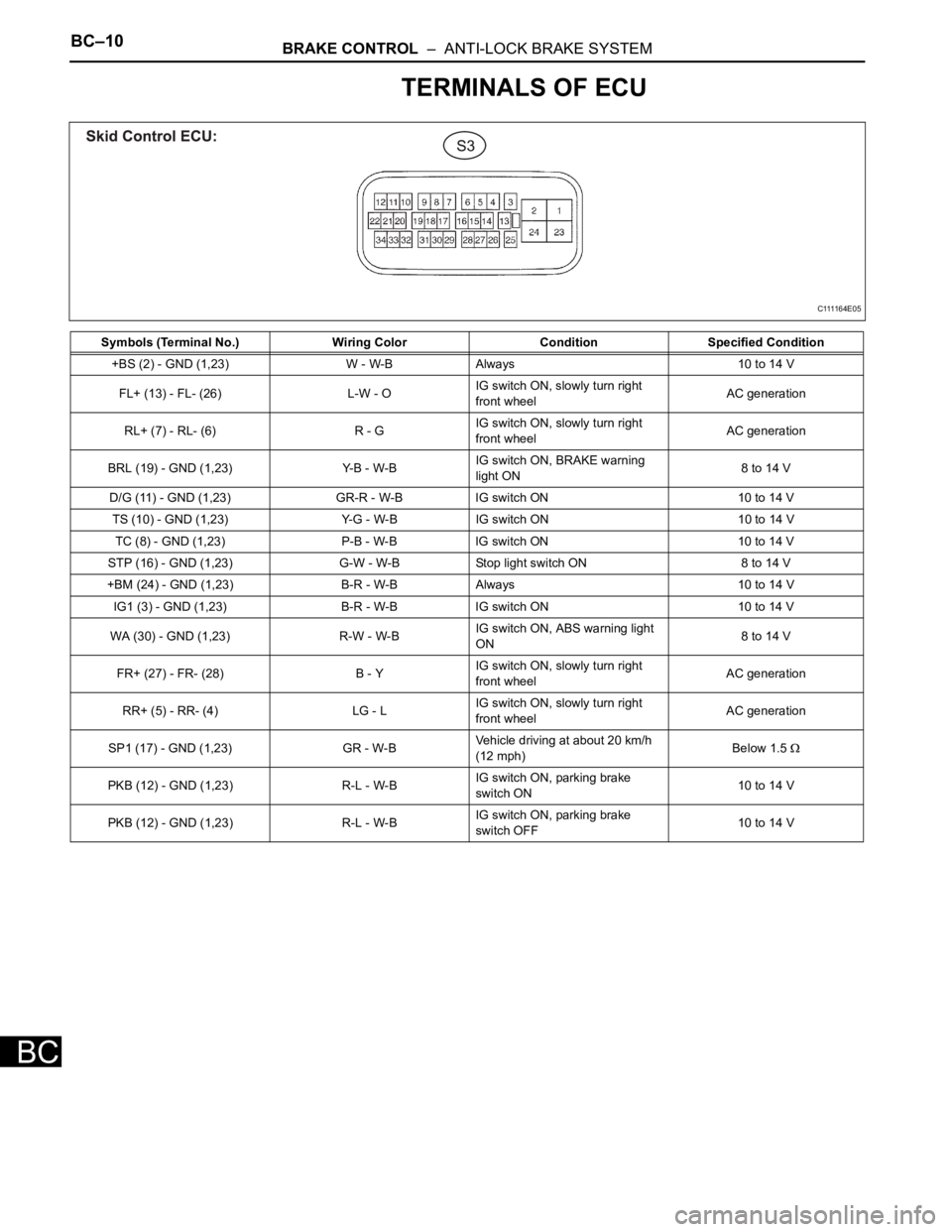
TERMINALS OF ECU
Symbols (Terminal No.) Wiring Color Condition Specified Condition
+BS (2) - GND (1,23) W - W-B Always 10 to 14 V
FL+ (13) - FL- (26) L-W - OIG switch ON, slowly turn right
front wheelAC generation
RL+ (7) - RL- (6) R - GIG switch ON, slowly turn right
front wheelAC generation
BRL (19) - GND (1,23) Y-B - W-BIG switch ON, BRAKE warning
light ON8 to 14 V
D/G (11) - GND (1,23) GR-R - W-B IG switch ON 10 to 14 V
TS (10) - GND (1,23) Y-G - W-B IG switch ON 10 to 14 V
TC (8) - GND (1,23) P-B - W-B IG switch ON 10 to 14 V
STP (16) - GND (1,23) G-W - W-B Stop light switch ON 8 to 14 V
+BM (24) - GND (1,23) B-R - W-B Always 10 to 14 V
IG1 (3) - GND (1,23) B-R - W-B IG switch ON 10 to 14 V
WA (30) - GND (1,23) R-W - W-BIG switch ON, ABS warning light
ON8 to 14 V
FR+ (27) - FR- (28) B - YIG switch ON, slowly turn right
front wheelAC generation
RR+ (5) - RR- (4) LG - LIG switch ON, slowly turn right
front wheelAC generation
SP1 (17) - GND (1,23) GR - W-BVehicle driving at about 20 km/h
(12 mph)Below 1.5
PKB (12) - GND (1,23) R-L - W-BIG switch ON, parking brake
switch ON10 to 14 V
PKB (12) - GND (1,23) R-L - W-BIG switch ON, parking brake
switch OFF10 to 14 V
C111164E05
Page 2374 of 3000
BC–26BRAKE CONTROL – ANTI-LOCK BRAKE SYSTEM
BC
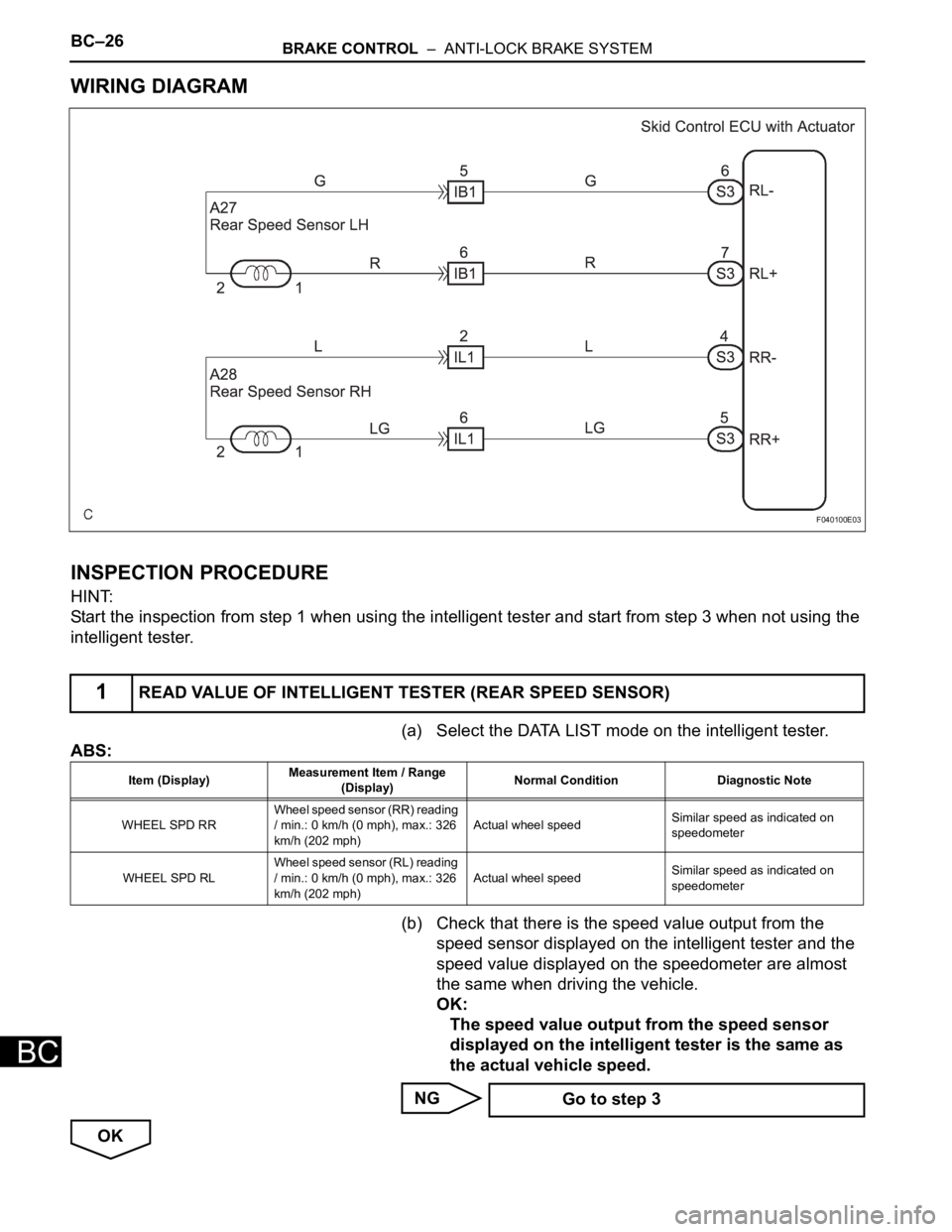
WIRING DIAGRAM
INSPECTION PROCEDURE
HINT:
Start the inspection from step 1 when using the intelligent tester and start from step 3 when not using the
intelligent tester.
(a) Select the DATA LIST mode on the intelligent tester.
ABS:
(b) Check that there is the speed value output from the
speed sensor displayed on the intelligent tester and the
speed value displayed on the speedometer are almost
the same when driving the vehicle.
OK:
The speed value output from the speed sensor
displayed on the intelligent tester is the same as
the actual vehicle speed.
NG
OK
1READ VALUE OF INTELLIGENT TESTER (REAR SPEED SENSOR)
F040100E03
Item (Display)Measurement Item / Range
(Display)Normal Condition Diagnostic Note
WHEEL SPD RRWheel speed sensor (RR) reading
/ min.: 0 km/h (0 mph), max.: 326
km/h (202 mph)Actual wheel speedSimilar speed as indicated on
speedometer
WHEEL SPD RLWheel speed sensor (RL) reading
/ min.: 0 km/h (0 mph), max.: 326
km/h (202 mph)Actual wheel speedSimilar speed as indicated on
speedometer
Go to step 3
Page 2380 of 3000
BC–10BRAKE CONTROL – ANTI-LOCK BRAKE SYSTEM
BC
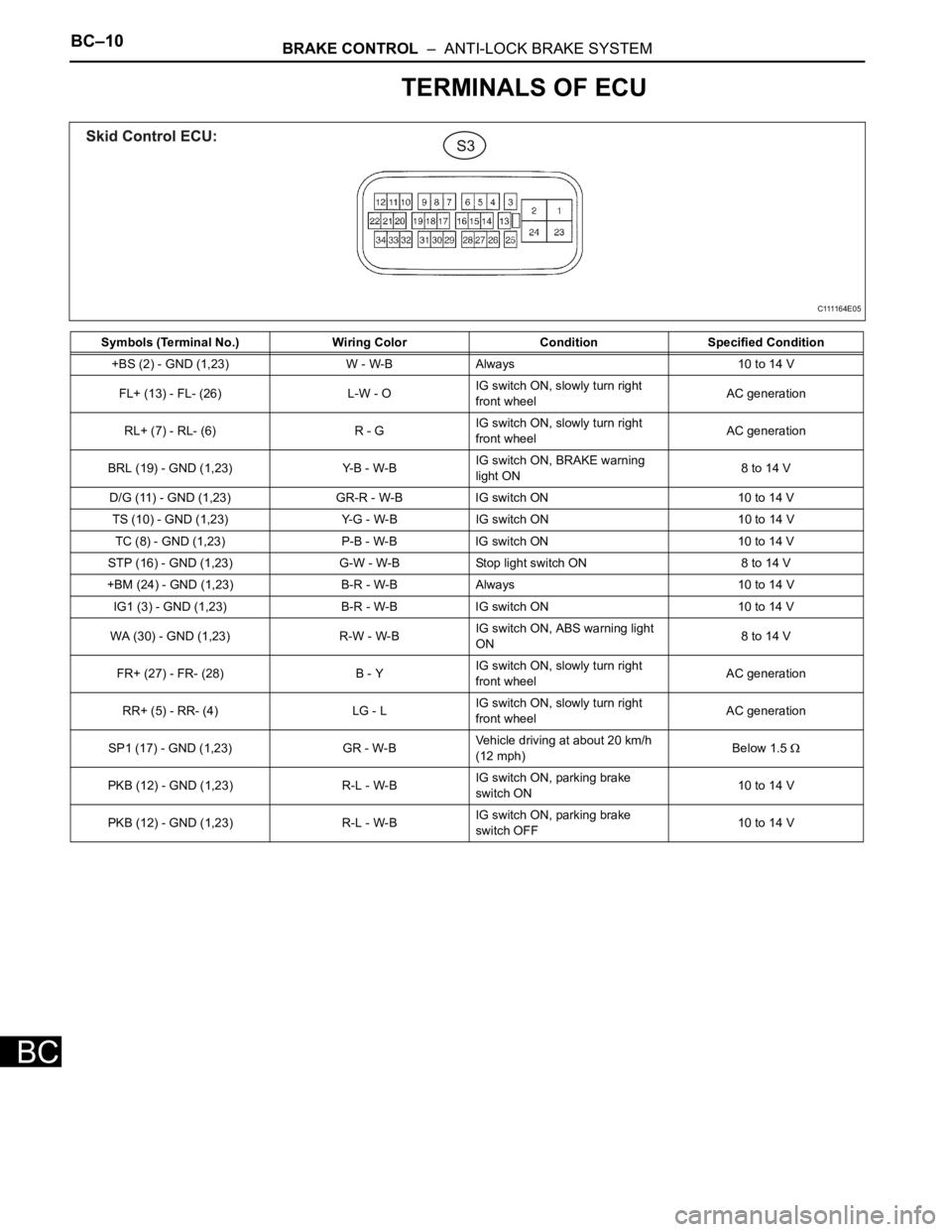
TERMINALS OF ECU
Symbols (Terminal No.) Wiring Color Condition Specified Condition
+BS (2) - GND (1,23) W - W-B Always 10 to 14 V
FL+ (13) - FL- (26) L-W - OIG switch ON, slowly turn right
front wheelAC generation
RL+ (7) - RL- (6) R - GIG switch ON, slowly turn right
front wheelAC generation
BRL (19) - GND (1,23) Y-B - W-BIG switch ON, BRAKE warning
light ON8 to 14 V
D/G (11) - GND (1,23) GR-R - W-B IG switch ON 10 to 14 V
TS (10) - GND (1,23) Y-G - W-B IG switch ON 10 to 14 V
TC (8) - GND (1,23) P-B - W-B IG switch ON 10 to 14 V
STP (16) - GND (1,23) G-W - W-B Stop light switch ON 8 to 14 V
+BM (24) - GND (1,23) B-R - W-B Always 10 to 14 V
IG1 (3) - GND (1,23) B-R - W-B IG switch ON 10 to 14 V
WA (30) - GND (1,23) R-W - W-BIG switch ON, ABS warning light
ON8 to 14 V
FR+ (27) - FR- (28) B - YIG switch ON, slowly turn right
front wheelAC generation
RR+ (5) - RR- (4) LG - LIG switch ON, slowly turn right
front wheelAC generation
SP1 (17) - GND (1,23) GR - W-BVehicle driving at about 20 km/h
(12 mph)Below 1.5
PKB (12) - GND (1,23) R-L - W-BIG switch ON, parking brake
switch ON10 to 14 V
PKB (12) - GND (1,23) R-L - W-BIG switch ON, parking brake
switch OFF10 to 14 V
C111164E05
Page 2387 of 3000
BC–20BRAKE CONTROL – ANTI-LOCK BRAKE SYSTEM
BC
HINT:
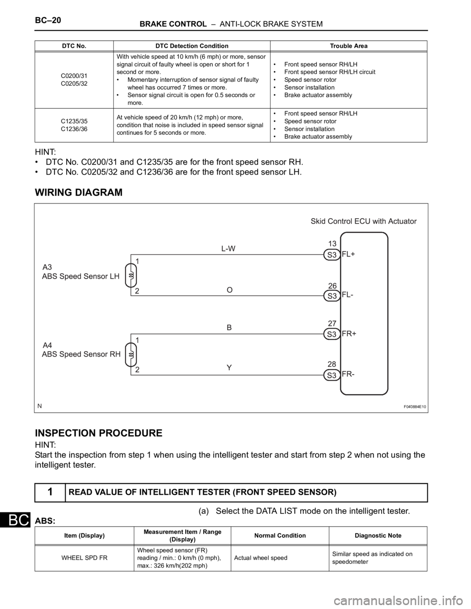
• DTC No. C0200/31 and C1235/35 are for the front speed sensor RH.
• DTC No. C0205/32 and C1236/36 are for the front speed sensor LH.
WIRING DIAGRAM
INSPECTION PROCEDURE
HINT:
Start the inspection from step 1 when using the intelligent tester and start from step 2 when not using the
intelligent tester.
(a) Select the DATA LIST mode on the intelligent tester.
ABS:
DTC No. DTC Detection Condition Trouble Area
C0200/31
C0205/32With vehicle speed at 10 km/h (6 mph) or more, sensor
signal circuit of faulty wheel is open or short for 1
second or more.
• Momentary interruption of sensor signal of faulty
wheel has occurred 7 times or more.
• Sensor signal circuit is open for 0.5 seconds or
more.• Front speed sensor RH/LH
• Front speed sensor RH/LH circuit
• Speed sensor rotor
• Sensor installation
• Brake actuator assembly
C1235/35
C1236/36At vehicle speed of 20 km/h (12 mph) or more,
condition that noise is included in speed sensor signal
continues for 5 seconds or more.• Front speed sensor RH/LH
• Speed sensor rotor
• Sensor installation
• Brake actuator assembly
1READ VALUE OF INTELLIGENT TESTER (FRONT SPEED SENSOR)
F040884E10
Item (Display)Measurement Item / Range
(Display)Normal Condition Diagnostic Note
WHEEL SPD FRWheel speed sensor (FR)
reading / min.: 0 km/h (0 mph),
max.: 326 km/h(202 mph)Actual wheel speedSimilar speed as indicated on
speedometer
Page 2392 of 3000
BRAKE CONTROL – ANTI-LOCK BRAKE SYSTEMBC–31
BC
DESCRIPTION
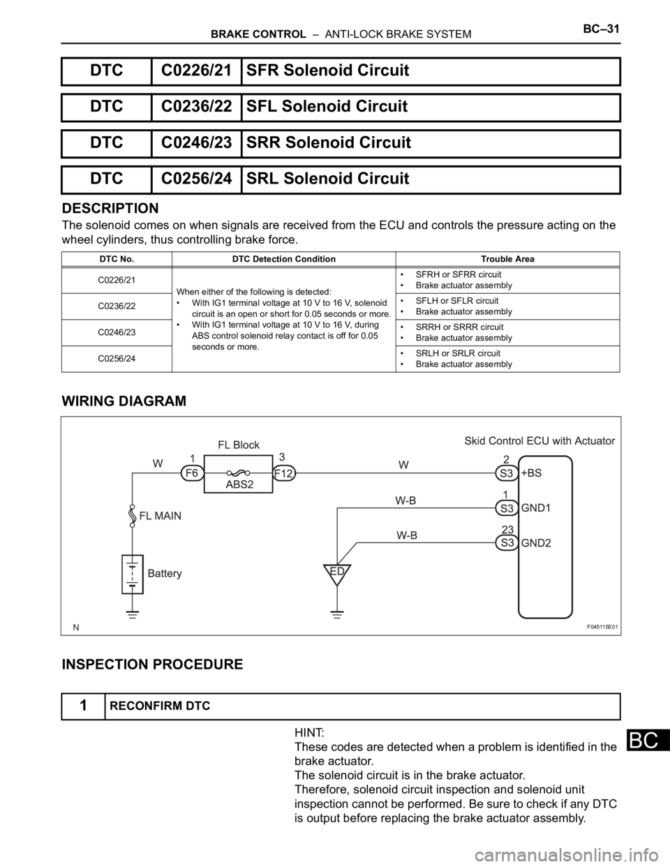
The solenoid comes on when signals are received from the ECU and controls the pressure acting on the
wheel cylinders, thus controlling brake force.
WIRING DIAGRAM
INSPECTION PROCEDURE
HINT:
These codes are detected when a problem is identified in the
brake actuator.
The solenoid circuit is in the brake actuator.
Therefore, solenoid circuit inspection and solenoid unit
inspection cannot be performed. Be sure to check if any DTC
is output before replacing the brake actuator assembly.
DTC C0226/21 SFR Solenoid Circuit
DTC C0236/22 SFL Solenoid Circuit
DTC C0246/23 SRR Solenoid Circuit
DTC C0256/24 SRL Solenoid Circuit
DTC No. DTC Detection Condition Trouble Area
C0226/21
When either of the following is detected:
• With IG1 terminal voltage at 10 V to 16 V, solenoid
circuit is an open or short for 0.05 seconds or more.
• With IG1 terminal voltage at 10 V to 16 V, during
ABS control solenoid relay contact is off for 0.05
seconds or more.• SFRH or SFRR circuit
• Brake actuator assembly
C0236/22• SFLH or SFLR circuit
• Brake actuator assembly
C0246/23• SRRH or SRRR circuit
• Brake actuator assembly
C0256/24• SRLH or SRLR circuit
• Brake actuator assembly
1RECONFIRM DTC
F045115E01
Page 2394 of 3000
BRAKE CONTROL – ANTI-LOCK BRAKE SYSTEMBC–33
BC
DESCRIPTION
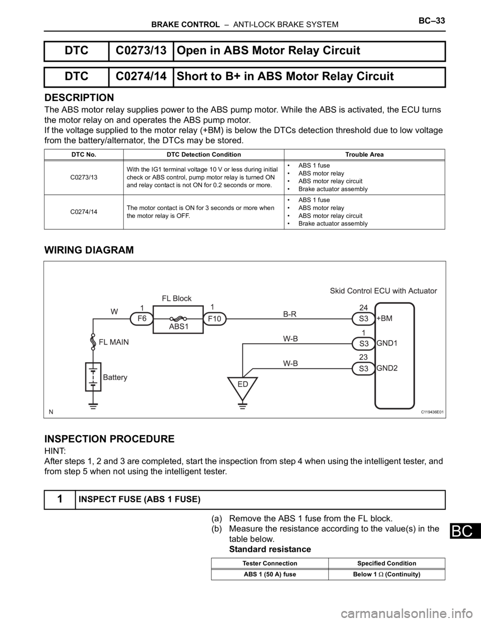
The ABS motor relay supplies power to the ABS pump motor. While the ABS is activated, the ECU turns
the motor relay on and operates the ABS pump motor.
If the voltage supplied to the motor relay (+BM) is below the DTCs detection threshold due to low voltage
from the battery/alternator, the DTCs may be stored.
WIRING DIAGRAM
INSPECTION PROCEDURE
HINT:
After steps 1, 2 and 3 are completed, start the inspection from step 4 when using the intelligent tester, and
from step 5 when not using the intelligent tester.
(a) Remove the ABS 1 fuse from the FL block.
(b) Measure the resistance according to the value(s) in the
table below.
Standard resistance
DTC C0273/13 Open in ABS Motor Relay Circuit
DTC C0274/14 Short to B+ in ABS Motor Relay Circuit
DTC No. DTC Detection Condition Trouble Area
C0273/13With the IG1 terminal voltage 10 V or less during initial
check or ABS control, pump motor relay is turned ON
and relay contact is not ON for 0.2 seconds or more.• ABS 1 fuse
• ABS motor relay
• ABS motor relay circuit
• Brake actuator assembly
C0274/14The motor contact is ON for 3 seconds or more when
the motor relay is OFF.• ABS 1 fuse
• ABS motor relay
• ABS motor relay circuit
• Brake actuator assembly
1INSPECT FUSE (ABS 1 FUSE)
C119436E01
Tester Connection Specified Condition
ABS 1 (50 A) fuse Below 1
(Continuity)
Page 2397 of 3000
BC–36BRAKE CONTROL – ANTI-LOCK BRAKE SYSTEM
BC
DESCRIPTION
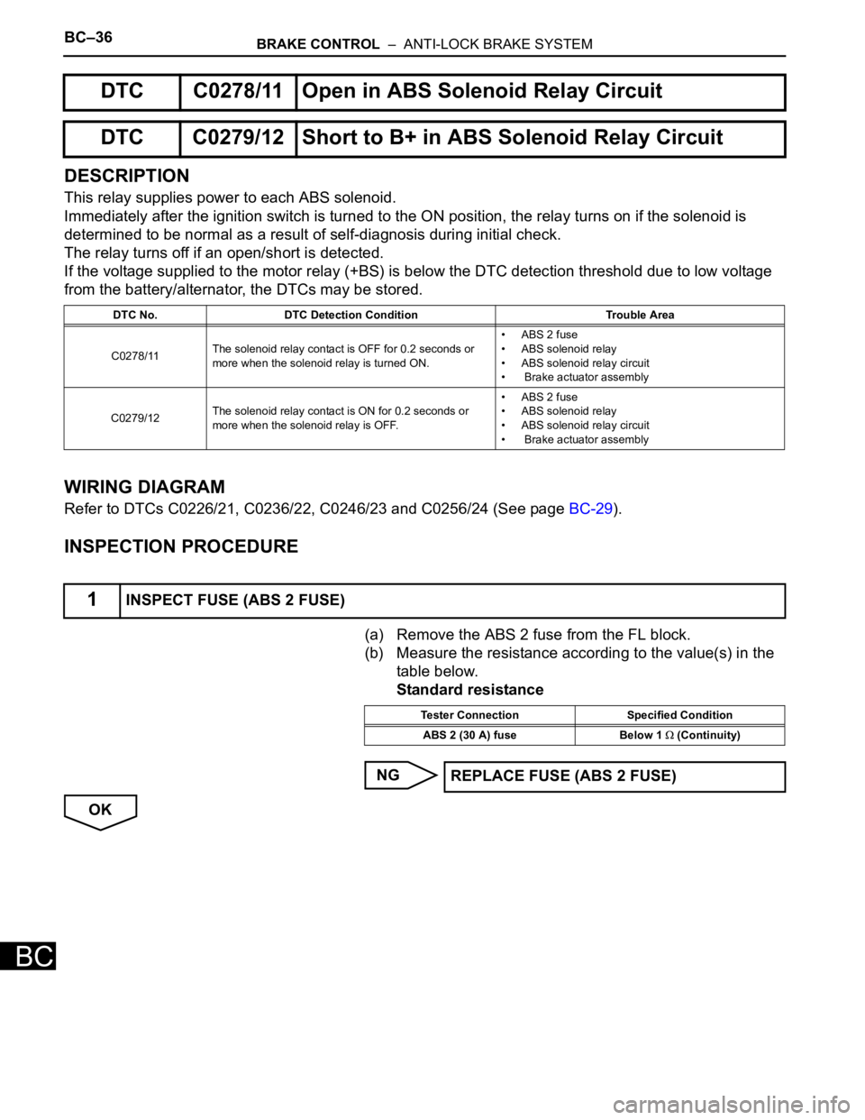
This relay supplies power to each ABS solenoid.
Immediately after the ignition switch is turned to the ON position, the relay turns on if the solenoid is
determined to be normal as a result of self-diagnosis during initial check.
The relay turns off if an open/short is detected.
If the voltage supplied to the motor relay (+BS) is below the DTC detection threshold due to low voltage
from the battery/alternator, the DTCs may be stored.
WIRING DIAGRAM
Refer to DTCs C0226/21, C0236/22, C0246/23 and C0256/24 (See page BC-29).
INSPECTION PROCEDURE
(a) Remove the ABS 2 fuse from the FL block.
(b) Measure the resistance according to the value(s) in the
table below.
Standard resistance
NG
OK
DTC C0278/11 Open in ABS Solenoid Relay Circuit
DTC C0279/12 Short to B+ in ABS Solenoid Relay Circuit
DTC No. DTC Detection Condition Trouble Area
C0278/11The solenoid relay contact is OFF for 0.2 seconds or
more when the solenoid relay is turned ON.• ABS 2 fuse
• ABS solenoid relay
• ABS solenoid relay circuit
• Brake actuator assembly
C0279/12The solenoid relay contact is ON for 0.2 seconds or
more when the solenoid relay is OFF.• ABS 2 fuse
• ABS solenoid relay
• ABS solenoid relay circuit
• Brake actuator assembly
1INSPECT FUSE (ABS 2 FUSE)
Tester Connection Specified Condition
ABS 2 (30 A) fuse Below 1
(Continuity)
REPLACE FUSE (ABS 2 FUSE)