Page 1125 of 3000

FU–42GR-FE FUEL – FUEL SYSTEM
FU
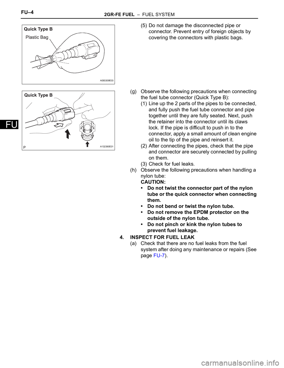
(5) Do not damage the disconnected pipe or
connector. Prevent entry of foreign objects by
covering the connectors with plastic bags.
(g) Observe the following precautions when connecting
the fuel tube connector (Quick Type B):
(1) Line up the 2 parts of the pipes to be connected,
and fully push the fuel tube connector and pipe
together until they are fully seated. Next, push
the retainer into the connector until its claws
lock. If the pipe is difficult to push in to the
connector, apply a small amount of clean engine
oil to the tip of the pipe and reinsert it.
(2) After connecting the pipes, check that the pipe
and connector are securely connected by pulling
on them.
(3) Check for fuel leaks.
(h) Observe the following precautions when handling a
nylon tube:
CAUTION:
• Do not twist the connector part of the nylon
tube or the quick connector when connecting
them.
• Do not bend or twist the nylon tube.
• Do not remove the EPDM protector on the
outside of the nylon tube.
• Do not pinch or kink the nylon tubes to
prevent fuel leakage.
4. INSPECT FOR FUEL LEAK
(a) Check that there are no fuel leaks from the fuel
system after doing any maintenance or repairs (See
page FU-7).
A093309E03
A132390E01
Page 1192 of 3000

EC–182GR-FE EMISSION CONTROL – AIR FUEL RATIO SENSOR (for 2WD)
EC
ON-VEHICLE INSPECTION
HINT:
The type of ignition switch on this model differs according to
the specifications of the vehicle. For the expressions used in
this section, refer to the "EXPRESSIONS OF IGNITION
SWITCH" precaution (See page ES-1).
1. CHECK AIR FUEL RATIO COMPENSATION SYSTEM
(a) Connect the intelligent tester to the DLC3.
(b) Turn the ignition switch to the ON position.
(c) Select the following menu items: Data List / A/FS B1
S1 and O2S B1 S2.
(d) Warm up the A/F sensor with the engine speed at
2500 rpm for approximately 2 minutes.
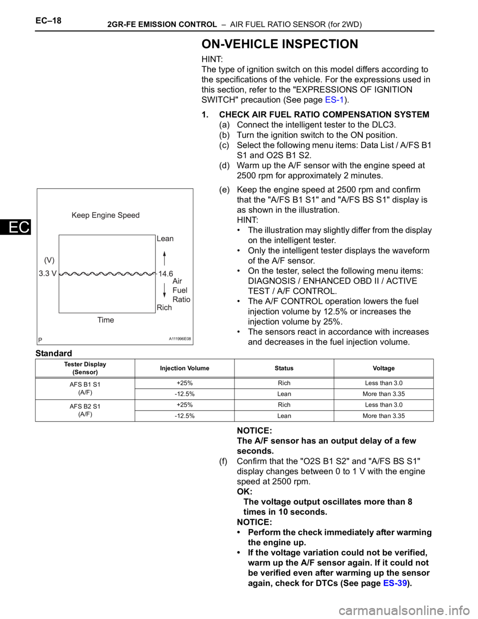
(e) Keep the engine speed at 2500 rpm and confirm
that the "A/FS B1 S1" and "A/FS BS S1" display is
as shown in the illustration.
HINT:
• The illustration may slightly differ from the display
on the intelligent tester.
• Only the intelligent tester displays the waveform
of the A/F sensor.
• On the tester, select the following menu items:
DIAGNOSIS / ENHANCED OBD II / ACTIVE
TEST / A/F CONTROL.
• The A/F CONTROL operation lowers the fuel
injection volume by 12.5% or increases the
injection volume by 25%.
• The sensors react in accordance with increases
and decreases in the fuel injection volume.
Standard
NOTICE:
The A/F sensor has an output delay of a few
seconds.
(f) Confirm that the "O2S B1 S2" and "A/FS BS S1"
display changes between 0 to 1 V with the engine
speed at 2500 rpm.
OK:
The voltage output oscillates more than 8
times in 10 seconds.
NOTICE:
• Perform the check immediately after warming
the engine up.
• If the voltage variation could not be verified,
warm up the A/F sensor again. If it could not
be verified even after warming up the sensor
again, check for DTCs (See page ES-39).
A111996E08
Tester Display
(Sensor)Injection Volume Status Voltage
AFS B1 S1
(A/F)+25% Rich Less than 3.0
-12.5% Lean More than 3.35
AFS B2 S1
(A/F)+25% Rich Less than 3.0
-12.5% Lean More than 3.35
Page 1196 of 3000

2GR-FE EMISSION CONTROL – AIR FUEL RATIO SENSOR (for 4WD)EC–25
EC
ON-VEHICLE INSPECTION
HINT:
The type of ignition switch on this model differs according to
the specifications of the vehicle. For the expressions used in
this section, refer to the "EXPRESSIONS OF IGNITION
SWITCH" precaution (See page ES-1).
1. CHECK AIR FUEL RATIO COMPENSATION SYSTEM
(a) Connect the intelligent tester to the DLC3.
(b) Turn the ignition switch to the ON position.
(c) Select the following menu items: Data List / A/FS B1
S1 and O2S B1 S2.
(d) Warm up the A/F sensor with the engine speed at
2500 rpm for approximately 2 minutes.
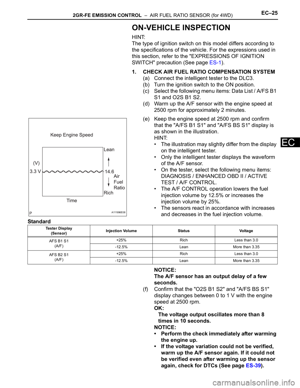
(e) Keep the engine speed at 2500 rpm and confirm
that the "A/FS B1 S1" and "A/FS BS S1" display is
as shown in the illustration.
HINT:
• The illustration may slightly differ from the display
on the intelligent tester.
• Only the intelligent tester displays the waveform
of the A/F sensor.
• On the tester, select the following menu items:
DIAGNOSIS / ENHANCED OBD II / ACTIVE
TEST / A/F CONTROL.
• The A/F CONTROL operation lowers the fuel
injection volume by 12.5% or increases the
injection volume by 25%.
• The sensors react in accordance with increases
and decreases in the fuel injection volume.
Standard
NOTICE:
The A/F sensor has an output delay of a few
seconds.
(f) Confirm that the "O2S B1 S2" and "A/FS BS S1"
display changes between 0 to 1 V with the engine
speed at 2500 rpm.
OK:
The voltage output oscillates more than 8
times in 10 seconds.
NOTICE:
• Perform the check immediately after warming
the engine up.
• If the voltage variation could not be verified,
warm up the A/F sensor again. If it could not
be verified even after warming up the sensor
again, check for DTCs (See page ES-39).
A111996E08
Tester Display
(Sensor)Injection Volume Status Voltage
AFS B1 S1
(A/F)+25% Rich Less than 3.0
-12.5% Lean More than 3.35
AFS B2 S1
(A/F)+25% Rich Less than 3.0
-12.5% Lean More than 3.35
Page 2992 of 3000

SUPPLEMENTAL RESTRAINT SYSTEM – AIRBAG SYSTEMRS–15
RS
SYSTEM DESCRIPTION
1. GENERAL
(a) In conjunction with impact absorbing structure for a
frontal collision, the SRS (Supplemental Restraint
System) driver airbag and front passenger airbag
were designed to supplement seat belts in the event
of a frontal collision in order to help reduce shock to
the head and chest. This system is a 3-sensor type
airbag system to detect the impact during a frontal
collision using the center airbag sensor assembly
and front airbag sensors. It also operates the airbag
system and seat belt pretensioner.
(b) In order to detect the extent of the collision during
the initial stages of the collision in further detail, the
front airbag sensors have been changed from
mechanical type to electrical type deceleration
sensors. Accordingly, the deployment of the driver
airbag and front passenger airbag is controlled in
two stages according to the severity of the impact.
(c) In conjunction with impact absorbing structure for a
side collision, the front seat side airbag and curtain
shield airbag were designed to help reduce shock to
the driver, front passenger, and rear outer
passengers in the event of a side collision or
rollover.
(d) RSCA (Roll Sensing of Curtain Shield Airbags) is
used in order to deploy the curtain shield airbags
and the seat belt pretensioner for the driver and
front passenger, in the event that the vehicle rolls
over.
(e) The curtain shield airbag that helps reduce shock to
the front and rear seat occupants with a single
curtain shield airbag has been adopted. In
conjunction with this system, the side airbag
sensors have been installed at the bottom of the
center pillars and the rear airbag sensors have been
installed at the bottom of the rear pillars
respectively.
(f) In this system, a front side collision is detected by
the side airbag sensors in order to deploy the front
seat side airbag and curtain shield airbag. A rear
side collision is detected by the rear airbag sensors
and the center airbag sensor assembly in order to
deploy the curtain shield airbag.
(g) The center airbag sensor assembly sends the
airbag deployment signal to the ECM through BEAN
(Body Electronics Area Network) and CAN
(Controller Area Network) to operate the fuel pump
control.
(h) The center airbag sensor assembly sends the
airbag deployment signal to the body ECU via a
discrete line to operate collision door lock release
control.