Page 2246 of 3000

SP–64SUSPENSION – REAR AXLE BEAM
SP
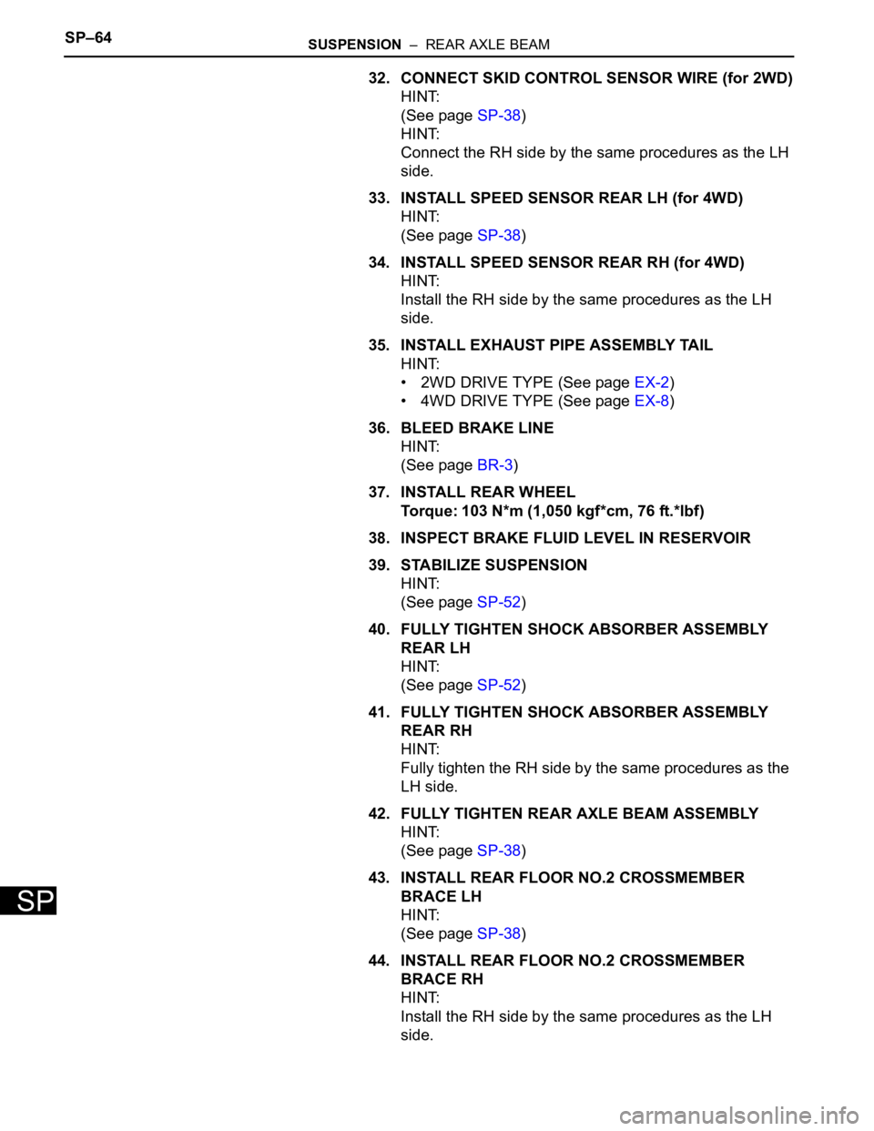
32. CONNECT SKID CONTROL SENSOR WIRE (for 2WD)
HINT:
(See page SP-38)
HINT:
Connect the RH side by the same procedures as the LH
side.
33. INSTALL SPEED SENSOR REAR LH (for 4WD)
HINT:
(See page SP-38)
34. INSTALL SPEED SENSOR REAR RH (for 4WD)
HINT:
Install the RH side by the same procedures as the LH
side.
35. INSTALL EXHAUST PIPE ASSEMBLY TAIL
HINT:
• 2WD DRIVE TYPE (See page EX-2)
• 4WD DRIVE TYPE (See page EX-8)
36. BLEED BRAKE LINE
HINT:
(See page BR-3)
37. INSTALL REAR WHEEL
Torque: 103 N*m (1,050 kgf*cm, 76 ft.*lbf)
38. INSPECT BRAKE FLUID LEVEL IN RESERVOIR
39. STABILIZE SUSPENSION
HINT:
(See page SP-52)
40. FULLY TIGHTEN SHOCK ABSORBER ASSEMBLY
REAR LH
HINT:
(See page SP-52)
41. FULLY TIGHTEN SHOCK ABSORBER ASSEMBLY
REAR RH
HINT:
Fully tighten the RH side by the same procedures as the
LH side.
42. FULLY TIGHTEN REAR AXLE BEAM ASSEMBLY
HINT:
(See page SP-38)
43. INSTALL REAR FLOOR NO.2 CROSSMEMBER
BRACE LH
HINT:
(See page SP-38)
44. INSTALL REAR FLOOR NO.2 CROSSMEMBER
BRACE RH
HINT:
Install the RH side by the same procedures as the LH
side.
Page 2255 of 3000

TW–4TIRE AND WHEEL – TIRE AND WHEEL SYSTEM
TW
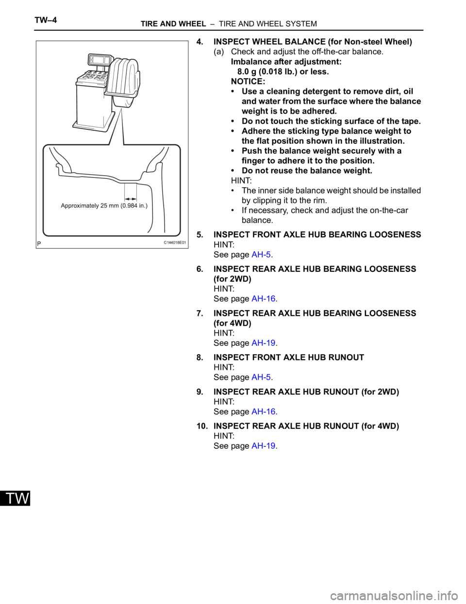
4. INSPECT WHEEL BALANCE (for Non-steel Wheel)
(a) Check and adjust the off-the-car balance.
Imbalance after adjustment:
8.0 g (0.018 lb.) or less.
NOTICE:
• Use a cleaning detergent to remove dirt, oil
and water from the surface where the balance
weight is to be adhered.
• Do not touch the sticking surface of the tape.
• Adhere the sticking type balance weight to
the flat position shown in the illustration.
• Push the balance weight securely with a
finger to adhere it to the position.
• Do not reuse the balance weight.
HINT:
• The inner side balance weight should be installed
by clipping it to the rim.
• If necessary, check and adjust the on-the-car
balance.
5. INSPECT FRONT AXLE HUB BEARING LOOSENESS
HINT:
See page AH-5.
6. INSPECT REAR AXLE HUB BEARING LOOSENESS
(for 2WD)
HINT:
See page AH-16.
7. INSPECT REAR AXLE HUB BEARING LOOSENESS
(for 4WD)
HINT:
See page AH-19.
8. INSPECT FRONT AXLE HUB RUNOUT
HINT:
See page AH-5.
9. INSPECT REAR AXLE HUB RUNOUT (for 2WD)
HINT:
See page AH-16.
10. INSPECT REAR AXLE HUB RUNOUT (for 4WD)
HINT:
See page AH-19.
C144018E01
Page 2464 of 3000

BC–102BRAKE CONTROL – VEHICLE STABILITY CONTROL SYSTEM
BC
OK
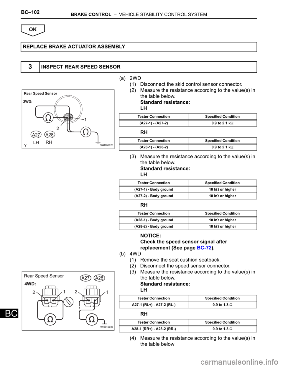
(a) 2WD
(1) Disconnect the skid control sensor connector.
(2) Measure the resistance according to the value(s) in
the table below.
Standard resistance:
LH
RH
(3) Measure the resistance according to the value(s) in
the table below.
Standard resistance:
LH
RH
NOTICE:
Check the speed sensor signal after
replacement (See page BC-72).
(b) 4WD
(1) Remove the seat cushion seatback.
(2) Disconnect the speed sensor connector.
(3) Measure the resistance according to the value(s) in
the table below.
Standard resistance:
LH
RH
(4) Measure the resistance according to the value(s) in
the table below REPLACE BRAKE ACTUATOR ASSEMBLY
3INSPECT REAR SPEED SENSOR
F041836E20
Tester Connection Specified Condition
(A27-1) - (A27-2) 0.9 to 2.1 k
Tester Connection Specified Condition
(A28-1) - (A28-2) 0.9 to 2.1 k
Tester Connection Specified Condition
(A27-1) - Body ground 10 k
or higher
(A27-2) - Body ground 10 k
or higher
Tester Connection Specified Condition
(A28-1) - Body ground 10 k
or higher
(A28-2) - Body ground 10 k
or higher
F013045E08
Tester Connection Specified Condition
A27-1 (RL+) - A27-2 (RL-) 0.9 to 1.3
Tester Connection Specified Condition
A28-1 (RR+) - A28-2 (RR-) 0.9 to 1.3
Page 2467 of 3000
BRAKE CONTROL – VEHICLE STABILITY CONTROL SYSTEMBC–105
BC
(b) 4WD
(1) Check the sensor installation.
OK:
There is no clearance between the sensor and
rear axle carrier.
The installation bolt is tightened properly.
Torque: 8.0 N*m (82 kgf*cm, 71 in.*lbf)
NOTICE:
Check the speed sensor signal after the replacement
(See page BC-72).
NG
OK
(a) Remove the rear axle hub and bearing, or rear drive
shaft (See page AH-16 for 2WD, or DS-21 for 4WD).
(b) Check the sensor rotor serrations.
OK:
No scratches, missing teeth or foreign objects.
Result
NOTICE:
Check the speed sensor signal after the replacement
(See page BC-72).
B
BR03795E46
INSTALL REAR SPEED SENSOR
CORRECTLY
7CHECK SPEED SENSOR ROTOR
F042859E02
Result Proceed to
OKA
NG (for 2WD)B
NG (for 4WD)C
REPLACE REAR AXLE HUB AND BEARING
ASSEMBLY (SPEED SENSOR ROTOR)
Page 2468 of 3000
BC–106BRAKE CONTROL – VEHICLE STABILITY CONTROL SYSTEM
BC
C
A
(a) Remove the rear speed sensor (See page BC-190 for
2WD or BC-194 for 4WD).
(b) Check the sensor tip.
OK:
No scratches or foreign matter on the sensor tip.
NOTICE:
• Check the speed sensor signal after the
replacement (See page BC-72).
• When replacing the brake actuator assembly,
perform zero point calibration (See page BC-70).
NG
OKREPLACE REAR DRIVE SHAFT ASSEMBLY
(SPEED SENSOR ROTOR)
8CHECK REAR SPEED SENSOR TIP
CLEAN OR REPLACE REAR SPEED
SENSOR
REPLACE BRAKE ACTUATOR ASSEMBLY
Page 2574 of 3000
BRAKE CONTROL – REAR SPEED SENSOR (for 4WD)BC–193
BC
BRAKE
BRAKE CONTROL
REAR SPEED SENSOR (for 4WD)
COMPONENTS
C119321E12
Page 2575 of 3000
BC–194BRAKE CONTROL – REAR SPEED SENSOR (for 4WD)
BC
REMOVAL
HINT:
Remove the RH side by the same procedure as the LH side.
1. REMOVE REAR WHEEL
2. REMOVE QUARTER TRIM PANEL ASSEMBLY
FRONT LH
HINT:
Remove the LH side by the same procedure as the RH
side (See page IR-9).
3. REMOVE REAR SPEED SENSOR
(a) Disconnect the speed sensor connector, and pull
out the sensor wire harness with grommet.
(b) Remove the clamp bolt holding the sensor harness
from the body.
(c) Remove the bolt and speed sensor rear LH.
NOTICE:
Keep the tip of the speed sensor rear LH clean.
F040305
G024305
G023898