2007 TOYOTA SIENNA Engine stay
[x] Cancel search: Engine stayPage 22 of 3000
![TOYOTA SIENNA 2007 Service Repair Manual ES–5222GR-FE ENGINE CONTROL SYSTEM – KNOCK SENSOR
ES
(g) Using a 5 mm socket hexagon wrench, remove the
4 bolts [G].
(h) Remove the 2 nuts, 2 bolts and intake air surge tank
[H].
(i) Remove th](/manual-img/14/57466/w960_57466-21.png "TOYOTA SIENNA 2007 Service Repair Manual ES–5222GR-FE ENGINE CONTROL SYSTEM – KNOCK SENSOR
ES
(g) Using a 5 mm socket hexagon wrench, remove the
4 bolts [G].
(h) Remove the 2 nuts, 2 bolts and intake air surge tank
[H].
(i) Remove th")
ES–5222GR-FE ENGINE CONTROL SYSTEM – KNOCK SENSOR
ES
(g) Using a 5 mm socket hexagon wrench, remove the
4 bolts [G].
(h) Remove the 2 nuts, 2 bolts and intake air surge tank
[H].
(i) Remove the gasket from the intake air surge tank [I].
9. REMOVE FUEL MAIN TUBE SUB-ASSEMBLY (See
page EM-30)
10. REMOVE INTAKE MANIFOLD (See page EM-39)
11. REMOVE KNOCK CONTROL SENSOR
(a) Disconnect the 2 knock sensor connectors.
(b) Remove the 2 bolts and then remove the 2 knock
control sensors.
INSPECTION
1. KNOCK CONTROL SENSOR
(a) Using an ohmmeter, measure the resistance
between the terminals.
Resistance:
120 to 280 k
at 20C (68F)
If the resistance is not specified, replace the knock
control sensor.
INSTALLATION
1. INSTALL KNOCK CONTROL SENSOR
(a) Install the 2 knock control sensors with the 2 bolts
as shown in the illustration.
Torque: 20 N*m (204 kgf*cm, 15 ft.*lbf)
(b) Connect the 2 knock control sensor connectors.
2. INSTALL INTAKE MANIFOLD (See page EM-49)
3. INSTALL FUEL MAIN TUBE SUB-ASSEMBLY (See
page EM-56)
4. INSTALL INTAKE AIR SURGE TANK
NOTICE:
DO NOT apply oil to the bolts listed below.
A129468E08
A129615
A065174
A132951E01
Tightening PartsTo r q u e
N*m (kgf*cm, ft.*lbf)QTY
Surge Tank and Intake Manifold 18 (184, 13) 4
No. 1 Surge Tank Stay and Surge Tank 21 (214, 15) 1
Throttle Body Bracket and Surge Tank 21 (214, 15) 1
Page 28 of 3000
2GR-FE ENGINE MECHANICAL – ENGINE ASSEMBLYEM–29
EM
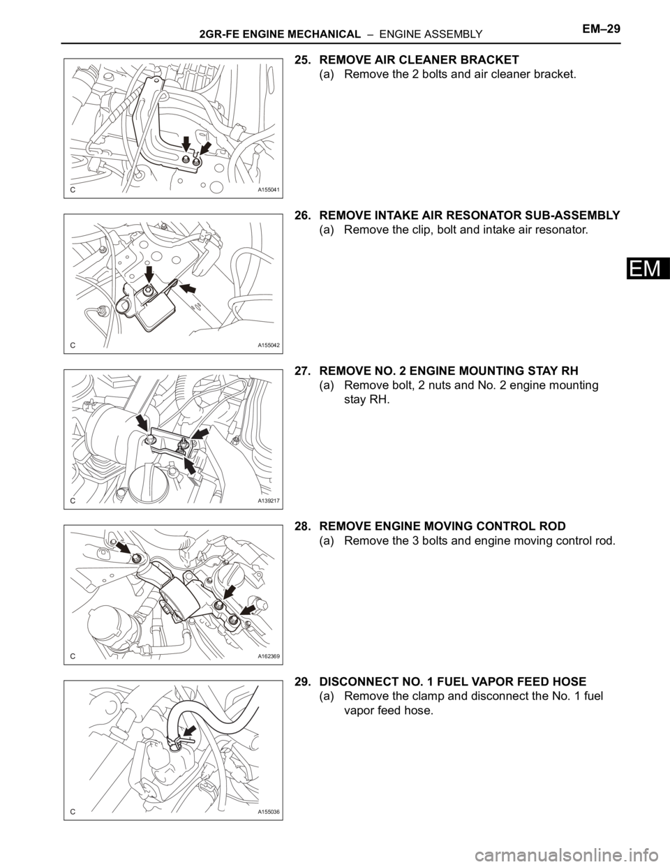
25. REMOVE AIR CLEANER BRACKET
(a) Remove the 2 bolts and air cleaner bracket.
26. REMOVE INTAKE AIR RESONATOR SUB-ASSEMBLY
(a) Remove the clip, bolt and intake air resonator.
27. REMOVE NO. 2 ENGINE MOUNTING STAY RH
(a) Remove bolt, 2 nuts and No. 2 engine mounting
stay RH.
28. REMOVE ENGINE MOVING CONTROL ROD
(a) Remove the 3 bolts and engine moving control rod.
29. DISCONNECT NO. 1 FUEL VAPOR FEED HOSE
(a) Remove the clamp and disconnect the No. 1 fuel
vapor feed hose.
A155041
A155042
A139217
A162369
A155036
Page 36 of 3000
2GR-FE ENGINE MECHANICAL – ENGINE ASSEMBLYEM–37
EM
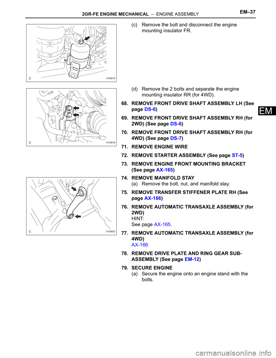
(c) Remove the bolt and disconnect the engine
mounting insulator FR.
(d) Remove the 2 bolts and separate the engine
mounting insulator RR (for 4WD).
68. REMOVE FRONT DRIVE SHAFT ASSEMBLY LH (See
page DS-6)
69. REMOVE FRONT DRIVE SHAFT ASSEMBLY RH (for
2WD) (See page DS-6)
70. REMOVE FRONT DRIVE SHAFT ASSEMBLY RH (for
4WD) (See page DS-7)
71. REMOVE ENGINE WIRE
72. REMOVE STARTER ASSEMBLY (See page ST-5)
73. REMOVE ENGINE FRONT MOUNTING BRACKET
(See page AX-165)
74. REMOVE MANIFOLD STAY
(a) Remove the bolt, nut, and manifold stay.
75. REMOVE TRANSFER STIFFENER PLATE RH (See
page AX-166)
76. REMOVE AUTOMATIC TRANSAXLE ASSEMBLY (for
2WD)
HINT:
See page AX-165.
77. REMOVE AUTOMATIC TRANSAXLE ASSEMBLY (for
4WD)
AX-166
78. REMOVE DRIVE PLATE AND RING GEAR SUB-
ASSEMBLY (See page EM-12)
79. SECURE ENGINE
(a) Secure the engine onto an engine stand with the
bolts.
A155019
A155018
A155023
Page 37 of 3000
EM–382GR-FE ENGINE MECHANICAL – ENGINE ASSEMBLY
EM
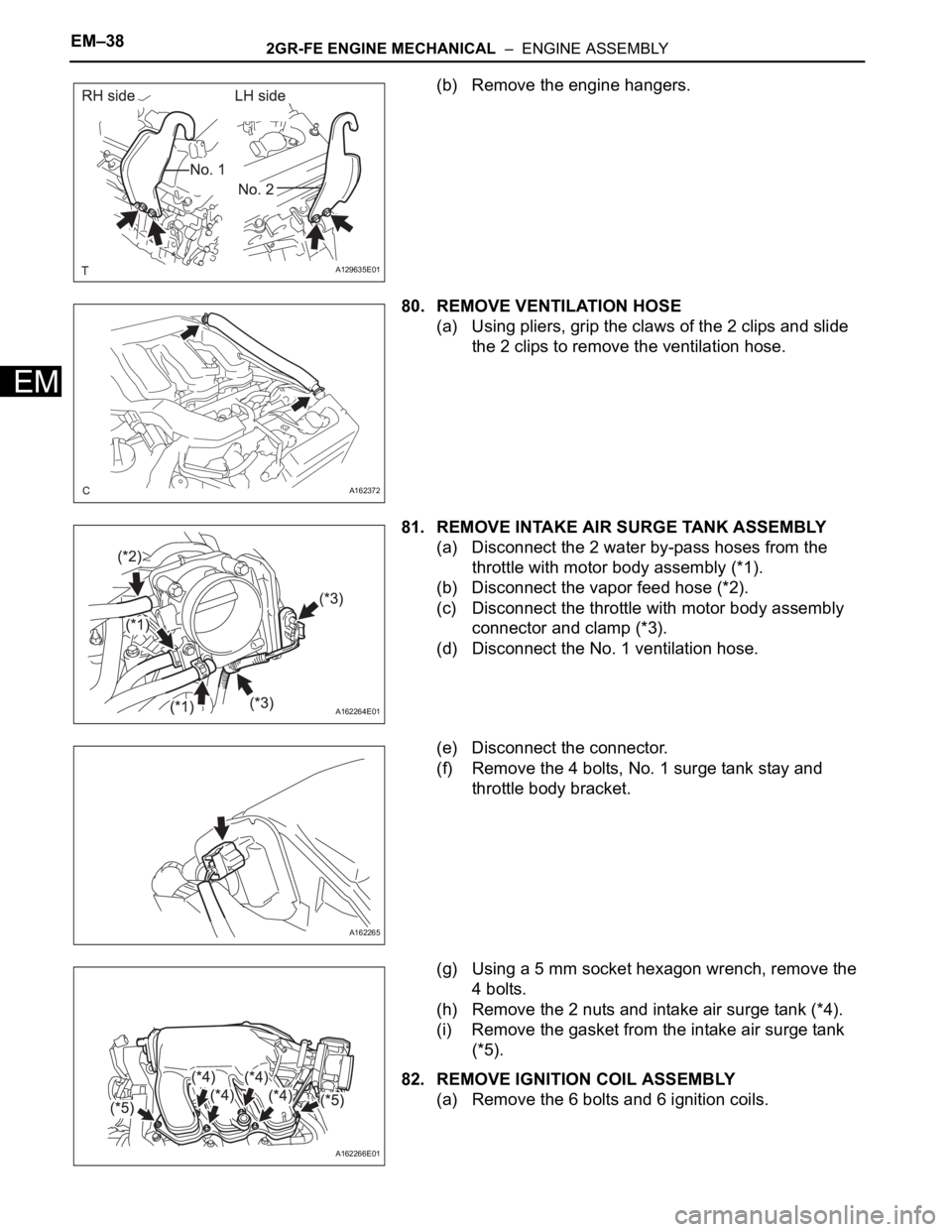
(b) Remove the engine hangers.
80. REMOVE VENTILATION HOSE
(a) Using pliers, grip the claws of the 2 clips and slide
the 2 clips to remove the ventilation hose.
81. REMOVE INTAKE AIR SURGE TANK ASSEMBLY
(a) Disconnect the 2 water by-pass hoses from the
throttle with motor body assembly (*1).
(b) Disconnect the vapor feed hose (*2).
(c) Disconnect the throttle with motor body assembly
connector and clamp (*3).
(d) Disconnect the No. 1 ventilation hose.
(e) Disconnect the connector.
(f) Remove the 4 bolts, No. 1 surge tank stay and
throttle body bracket.
(g) Using a 5 mm socket hexagon wrench, remove the
4 bolts.
(h) Remove the 2 nuts and intake air surge tank (*4).
(i) Remove the gasket from the intake air surge tank
(*5).
82. REMOVE IGNITION COIL ASSEMBLY
(a) Remove the 6 bolts and 6 ignition coils.
A129635E01
A162372
A162264E01
A162265
A162266E01
Page 38 of 3000
2GR-FE ENGINE MECHANICAL – ENGINE ASSEMBLYEM–39
EM
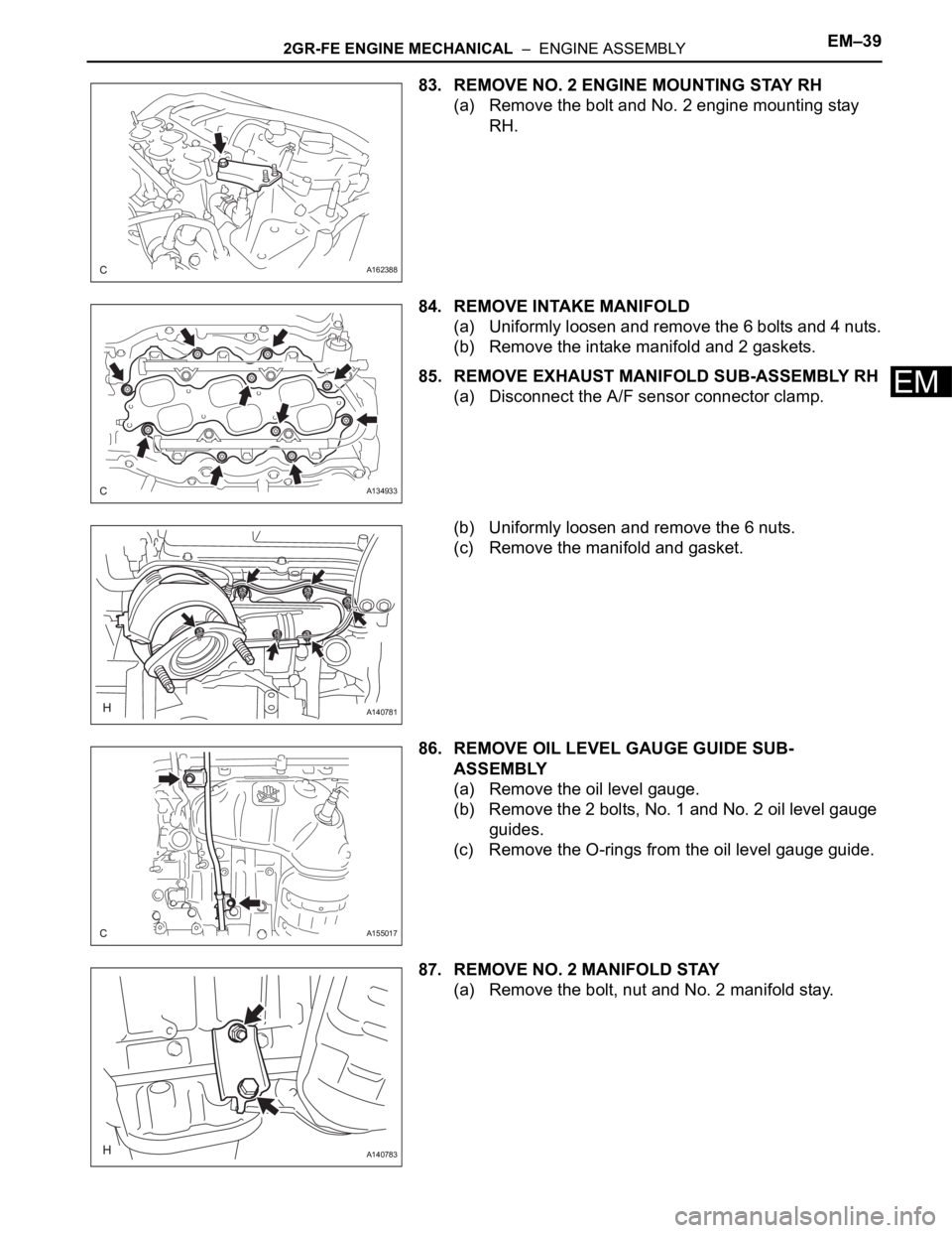
83. REMOVE NO. 2 ENGINE MOUNTING STAY RH
(a) Remove the bolt and No. 2 engine mounting stay
RH.
84. REMOVE INTAKE MANIFOLD
(a) Uniformly loosen and remove the 6 bolts and 4 nuts.
(b) Remove the intake manifold and 2 gaskets.
85. REMOVE EXHAUST MANIFOLD SUB-ASSEMBLY RH
(a) Disconnect the A/F sensor connector clamp.
(b) Uniformly loosen and remove the 6 nuts.
(c) Remove the manifold and gasket.
86. REMOVE OIL LEVEL GAUGE GUIDE SUB-
ASSEMBLY
(a) Remove the oil level gauge.
(b) Remove the 2 bolts, No. 1 and No. 2 oil level gauge
guides.
(c) Remove the O-rings from the oil level gauge guide.
87. REMOVE NO. 2 MANIFOLD STAY
(a) Remove the bolt, nut and No. 2 manifold stay.
A162388
A134933
A140781
A155017
A140783
Page 197 of 3000

SS–10SERVICE SPECIFICATIONS – 2GR-FE ENGINE MECHANICAL
SS
TORQUE SPECIFICATIONS
Part Tightened N*m kgf*cm ft.*lbf
Ignition coil assembly x Cylinder head cover sub-assembly 10 102 7
No. 1 engine hanger x Cylinder head sub-assembly RH 33 337 24
No. 2 engine hanger x Cylinder head sub-assembly LH 33 337 24
Engine mounting bracket RH x Cylinder block sub-assembly 54 551 40
No. 1 oil level gauge guide x Cylinder head sub-assembly 21 214 15
No. 2 oil level gauge guide x Cylinder block sub-assembly 21 214 15
No. 2 idler pulley sub-assembly x Timing chain cover sub-assembly 43 438 32
V-ribbed belt tensioner assembly x Cylinder block sub-assembly 43 438 32
Intake manifold x Cylinder head sub-assembly 21 214 15
Exhaust manifold sub-assembly RH x Cylinder head sub-assembly
RH21 214 15
Exhaust manifold sub-assembly LH x Cylinder head sub-assembly LH 21 214 15
Drive plate & ring gear sub-assembly x Crankshaft 83 850 61
Air cleaner case sub-assembly x Body 5.0 51 44 in.*lbf
Air cleaner case sub-assembly x Air cleaner bracket 5.0 51 44 in.*lbf
Engine coolant temperature x water by-pass joint RR 20 200 14
Engine assembly with Transaxle x Body A 85 867 63
B 32 329 24
No. 2 manifold stay x Exhaust manifold sub-assembly LH 34 347 25
No. 2 manifold stay x Cylinder block sub-assembly 34 347 25
No. 1 air cleaner inlet x Body 5.0 51 44 in.*lbf
No. 2 air cleaner inlet x Body 5.0 51 44 in.*lbf
Battery clamp x Body Bolt 5.5 56 49 in.*lbf
Nut 5.5 56 49 in.*lbf
Throttle body bracket x Intake air surge tank assembly 21 214 15
Throttle body bracket x Cylinder head cover sub-assembly RH 21 21415
No. 1 surge tank stay x Intake air surge tank assembly 21 214 15
No. 1 surge tank stay x Cylinder head cover sub-assembly RH 21 21415
No. 1 cowl top to cowl brace inner x Body 7.5 76 66 in.*lbf
No. 1 cowl top to cowl brace inner x Front outer cowl top panel sub-
assembly7.5 76 66 in.*lbf
Front outer cowl top panel sub-assembly x Body 7.5 76 66 in.*lbf
Fuel pump resistor x Front outer cowl top panel sub-assembly 7.576 66 in.*lbf
Radio setting condenser x Cylinder head cover sub-assembly RH 10102 7
Radio setting condense x Cylinder head cover sub-assembly LH 10 102 7
Intake air resonator sub-assembly x Body 5.0 51 44 in.*lbf
Air cleaner bracket x Body 7.8 80 69 in.*lbf
No. 1 vacuum switching valve assembly x Cylinder head cover sub-
assembly10 102 7
Engine mounting bracket RR x Cylinder block sub-assembly 64 650 47
Steering intermediate shaft x Steering gear 35 360 26
Stabilizer link x Shock absorber 74 755 55
Tie rod assembly x Steering gear 49 500 36
Front speed sensor x Front axle 8.0 85 71 in.*lbf
Front axle hub nut x Front drive shaft 294 2998 217
Cooler compressor assembly x V-ribbed belt tensioner 25 250 18
Cooler compressor assembly x Discharge hose sub-assembly 5.4 55 48 in.*lbf
Cooler compressor assembly x Suction hose sub-assembly 5.4 55 48 in.*lbf
Page 198 of 3000

SERVICE SPECIFICATIONS – 2GR-FE ENGINE MECHANICALSS–11
SS
Engine mounting control bracket x No. 1 engine
front mounting bracket LH
Bolt A 44 450 32
Bolt B 38 388 28
Nut 23 235 17
Engine assembly with Transaxle x Front frame
assemblyNut A 87 887 64
Nut B 95 969 70
Engine assembly with Transaxle x engine mounting insulator RR 78795 58
Drive shaft bearing bracket x Cylinder block sub-assembly 64 650 47
No. 2 exhaust manifold heat insulator x Exhaust manifold sub-
assembly LH8.5 87 75 in.*lbf
Engine oil pressure switch assembly x Oil pan sub-assembly 21 21415
No. 2 engine mounting stay RH x Intake manifold 21 214 15
No. 2 timing gear cover x Chain cover sub-assembly 6.0 61 53 in.*lbf
No. 1 engine front mounting bracket LH x Chain cover 54 551 40
Camshaft bearing cap x Camshaft housing 1st 10 102 7
2nd 16 163 12
Camshaft housing x Cylinder head sub-assembly 28 286 21
Chain tensioner No. 1 x Cylinder head sub-assembly 10 102 7
Chain tensioner No. 2 x Cylinder head sub-assembly 21 214 15
Chain tensioner No. 3 x Cylinder head sub-assembly 21 214 15
Camshaft timing gear assembly x Camshaft 100 1,020 74
Camshaft timing exhaust gear assembly x Camshaft 100 1,020 74
Engine rear oil seal retainer x Cylinder block sub-assembly 10 1027
Knock control sensor x Cylinder block sub-assembly 20 204 15
Water inlet pipe x Cylinder block sub-assembly 10 102 7
Cylinder head sub-assembly RH x Cylinder
block sub-assembly1st 36 367 27
2nd Turn 90
Turn 90Turn 90
3nd Turn 90Turn 90Turn 90
Cylinder head sub-assembly LH x Cylinder
block sub-assembly
Recessed head 1st 36 367 27
2nd Turn 90
Turn 90Turn 90
3nd Turn 90Turn 90Turn 90
14 mm (0.55 in.)
head30 306 22
Chain vibration damper No. 1 x Cylinder block sub-assembly 23 23017
No. 2 Idle gear shaft x Cylinder block sub-assembly 60 612 44
Timing chain cover plate x Timing chain cover sub-assembly 9.1 9381 in.*lbf
Timing chain cover sub-assembly x Cylinder
head and block
Areas 1: Bolt 21 214 15
Areas 2: Bolt 21 214 15
Areas 3: Bolt and
Nut21 214 15
Areas 4: Bolt A 43 438 32
Areas 4: Except
Bolt A21 214 15
Water pump assembly x Timing chain cover sub-assembly 9.1 93 81 in.*lbf
Oil pan baffle plate x Cylinder block sub-assembly 10 102 7
Oil pan stud bolt x Cylinder block and timing chain cover sub-
assembly10 102 7
Oil pan stud bolt x No. 2 oil pan sub-assembly 4.0 41 35 in.*lbf
Oil cooler stud bolt x Oil pan sub-assembly 10 102 7Part Tightened N*m kgf*cm ft.*lbf
Page 400 of 3000
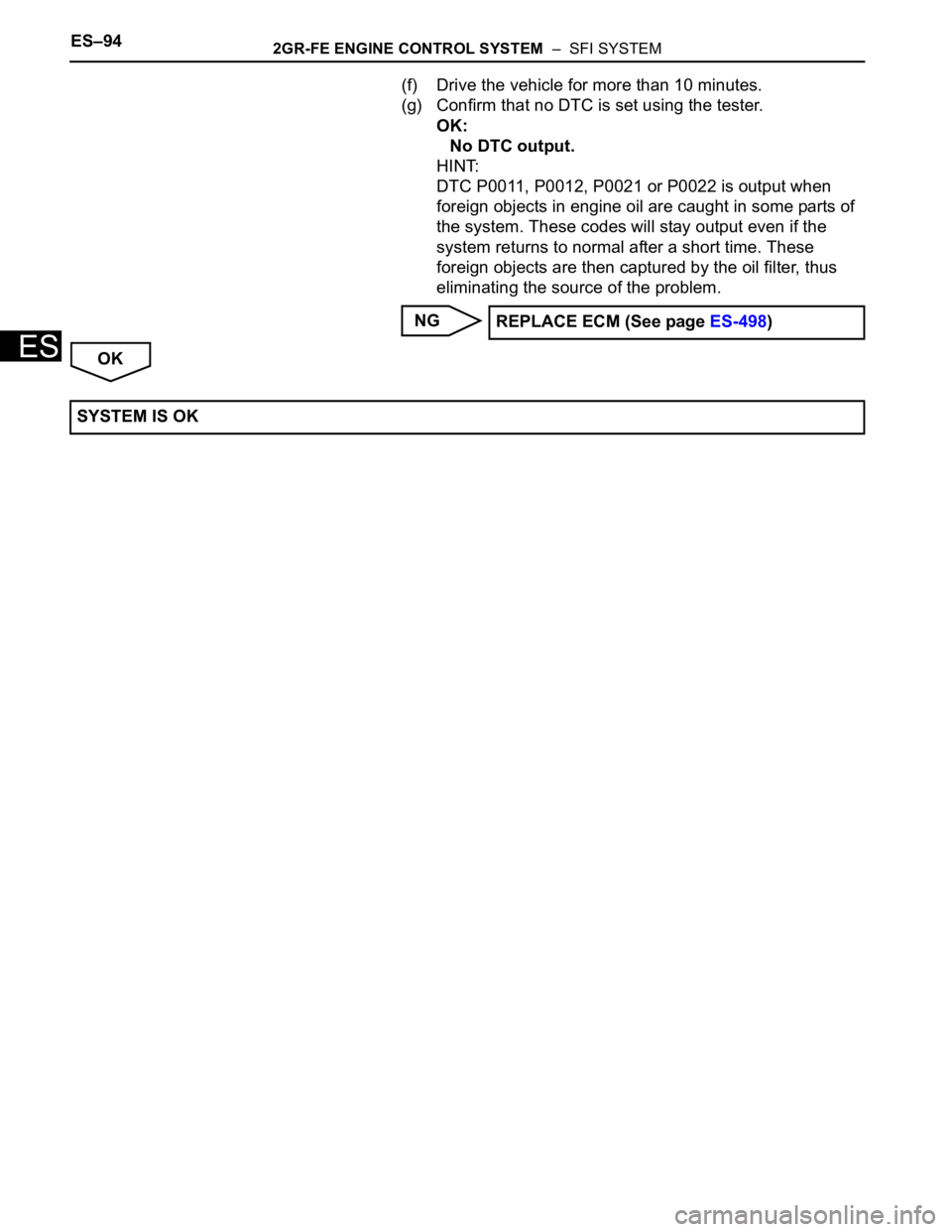
ES–942GR-FE ENGINE CONTROL SYSTEM – SFI SYSTEM
ES
(f) Drive the vehicle for more than 10 minutes.
(g) Confirm that no DTC is set using the tester.
OK:
No DTC output.
HINT:
DTC P0011, P0012, P0021 or P0022 is output when
foreign objects in engine oil are caught in some parts of
the system. These codes will stay output even if the
system returns to normal after a short time. These
foreign objects are then captured by the oil filter, thus
eliminating the source of the problem.
NG
OKREPLACE ECM (See page ES-498)
SYSTEM IS OK