Page 2098 of 3000
DRIVE SHAFT – REAR DRIVE SHAFT (for 4WD)DS–23
DS
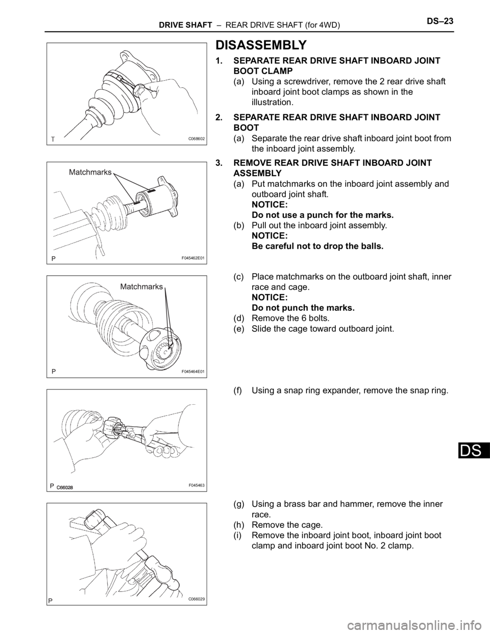
DISASSEMBLY
1. SEPARATE REAR DRIVE SHAFT INBOARD JOINT
BOOT CLAMP
(a) Using a screwdriver, remove the 2 rear drive shaft
inboard joint boot clamps as shown in the
illustration.
2. SEPARATE REAR DRIVE SHAFT INBOARD JOINT
BOOT
(a) Separate the rear drive shaft inboard joint boot from
the inboard joint assembly.
3. REMOVE REAR DRIVE SHAFT INBOARD JOINT
ASSEMBLY
(a) Put matchmarks on the inboard joint assembly and
outboard joint shaft.
NOTICE:
Do not use a punch for the marks.
(b) Pull out the inboard joint assembly.
NOTICE:
Be careful not to drop the balls.
(c) Place matchmarks on the outboard joint shaft, inner
race and cage.
NOTICE:
Do not punch the marks.
(d) Remove the 6 bolts.
(e) Slide the cage toward outboard joint.
(f) Using a snap ring expander, remove the snap ring.
(g) Using a brass bar and hammer, remove the inner
race.
(h) Remove the cage.
(i) Remove the inboard joint boot, inboard joint boot
clamp and inboard joint boot No. 2 clamp.
C068602
F045462E01
F045464E01
F045463
C066029
Page 2099 of 3000
DS–24DRIVE SHAFT – REAR DRIVE SHAFT (for 4WD)
DS
4. REMOVE REAR DRIVE SHAFT OUTBOARD JOINT
BOOT CLAMP
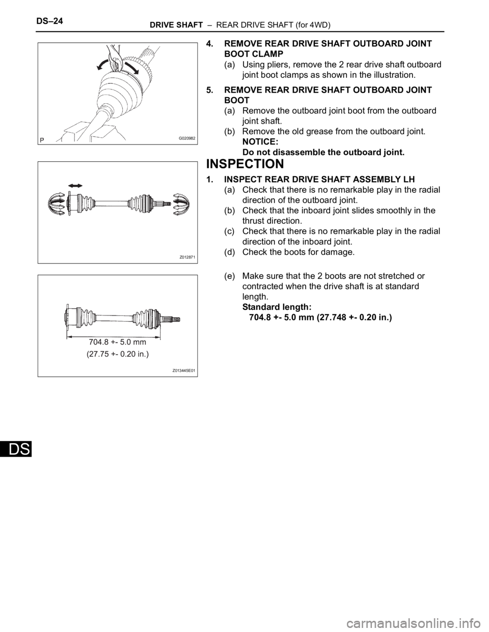
(a) Using pliers, remove the 2 rear drive shaft outboard
joint boot clamps as shown in the illustration.
5. REMOVE REAR DRIVE SHAFT OUTBOARD JOINT
BOOT
(a) Remove the outboard joint boot from the outboard
joint shaft.
(b) Remove the old grease from the outboard joint.
NOTICE:
Do not disassemble the outboard joint.
INSPECTION
1. INSPECT REAR DRIVE SHAFT ASSEMBLY LH
(a) Check that there is no remarkable play in the radial
direction of the outboard joint.
(b) Check that the inboard joint slides smoothly in the
thrust direction.
(c) Check that there is no remarkable play in the radial
direction of the inboard joint.
(d) Check the boots for damage.
(e) Make sure that the 2 boots are not stretched or
contracted when the drive shaft is at standard
length.
Standard length:
704.8 +- 5.0 mm (27.748 +- 0.20 in.)
G020982
Z012871
Z013445E01
Page 2100 of 3000
DRIVE SHAFT – REAR DRIVE SHAFT (for 4WD)DS–27
DS
INSTALLATION
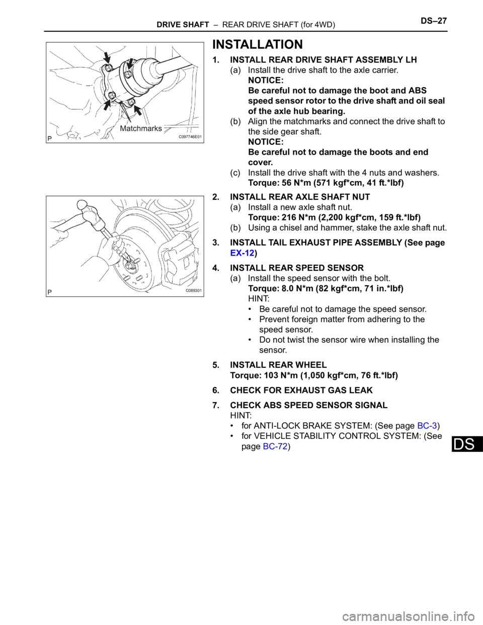
1. INSTALL REAR DRIVE SHAFT ASSEMBLY LH
(a) Install the drive shaft to the axle carrier.
NOTICE:
Be careful not to damage the boot and ABS
speed sensor rotor to the drive shaft and oil seal
of the axle hub bearing.
(b) Align the matchmarks and connect the drive shaft to
the side gear shaft.
NOTICE:
Be careful not to damage the boots and end
cover.
(c) Install the drive shaft with the 4 nuts and washers.
Torque: 56 N*m (571 kgf*cm, 41 ft.*lbf)
2. INSTALL REAR AXLE SHAFT NUT
(a) Install a new axle shaft nut.
Torque: 216 N*m (2,200 kgf*cm, 159 ft.*lbf)
(b) Using a chisel and hammer, stake the axle shaft nut.
3. INSTALL TAIL EXHAUST PIPE ASSEMBLY (See page
EX-12)
4. INSTALL REAR SPEED SENSOR
(a) Install the speed sensor with the bolt.
Torque: 8.0 N*m (82 kgf*cm, 71 in.*lbf)
HINT:
• Be careful not to damage the speed sensor.
• Prevent foreign matter from adhering to the
speed sensor.
• Do not twist the sensor wire when installing the
sensor.
5. INSTALL REAR WHEEL
Torque: 103 N*m (1,050 kgf*cm, 76 ft.*lbf)
6. CHECK FOR EXHAUST GAS LEAK
7. CHECK ABS SPEED SENSOR SIGNAL
HINT:
• for ANTI-LOCK BRAKE SYSTEM: (See page BC-3)
• for VEHICLE STABILITY CONTROL SYSTEM: (See
page BC-72)
C097746E01
C089301
Page 2101 of 3000
PP–44PREPARATION – DRIVE SHAFT
PP
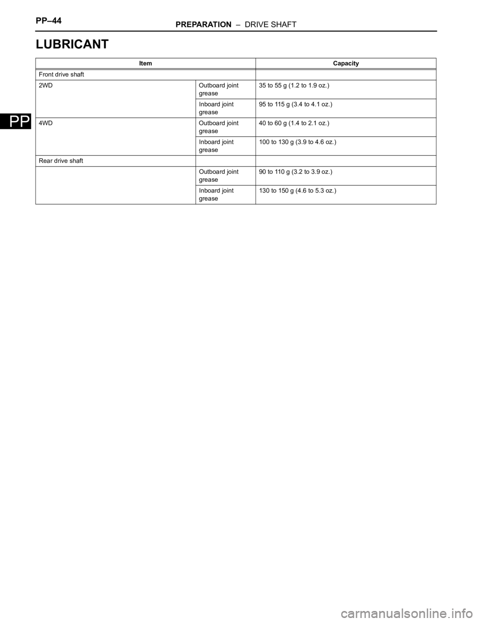
LUBRICANT
Item Capacity
Front drive shaft
2WD Outboard joint
grease35 to 55 g (1.2 to 1.9 oz.)
Inboard joint
grease95 to 115 g (3.4 to 4.1 oz.)
4WD Outboard joint
grease40 to 60 g (1.4 to 2.1 oz.)
Inboard joint
grease100 to 130 g (3.9 to 4.6 oz.)
Rear drive shaft
Outboard joint
grease90 to 110 g (3.2 to 3.9 oz.)
Inboard joint
grease130 to 150 g (4.6 to 5.3 oz.)
Page 2157 of 3000
AXLE – REAR AXLE HUB BOLTAH–13
AH
REPLACEMENT
HINT:
Replace the RH side using the same procedures as for the
LH side.
1. REMOVE REAR WHEEL
2. SEPARATE REAR DISC BRAKE CALIPER
ASSEMBLY LH
(a) Separate rear disc brake caliper assembly LH for
2WD and disk rear brake type (See page AH-16).
3. SEPARATE REAR DISC BRAKE CALIPER
ASSEMBLY LH
(a) Separate rear disc brake caliper assembly LH for
4WD and disk rear brake type (See page AH-19).
4. REMOVE REAR DISC
(a) Remove rear disc for disk rear brake type.
5. REMOVE REAR BRAKE DRUM SUB-ASSEMBLY
(a) Remove rear brake drum sub-assembly for drum
rear brake type.
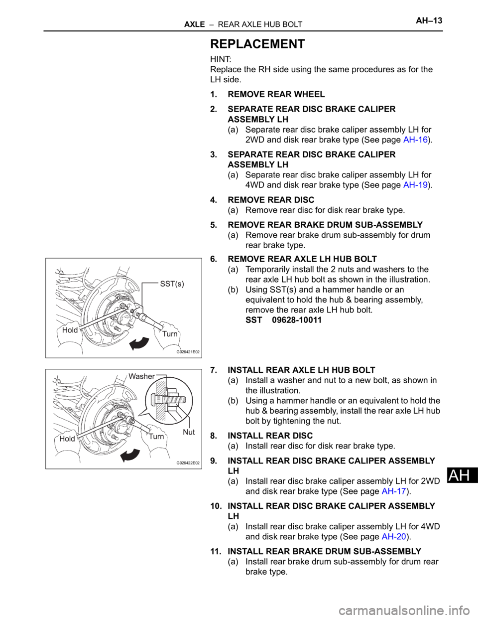
6. REMOVE REAR AXLE LH HUB BOLT
(a) Temporarily install the 2 nuts and washers to the
rear axle LH hub bolt as shown in the illustration.
(b) Using SST(s) and a hammer handle or an
equivalent to hold the hub & bearing assembly,
remove the rear axle LH hub bolt.
SST 09628-10011
7. INSTALL REAR AXLE LH HUB BOLT
(a) Install a washer and nut to a new bolt, as shown in
the illustration.
(b) Using a hammer handle or an equivalent to hold the
hub & bearing assembly, install the rear axle LH hub
bolt by tightening the nut.
8. INSTALL REAR DISC
(a) Install rear disc for disk rear brake type.
9. INSTALL REAR DISC BRAKE CALIPER ASSEMBLY
LH
(a) Install rear disc brake caliper assembly LH for 2WD
and disk rear brake type (See page AH-17).
10. INSTALL REAR DISC BRAKE CALIPER ASSEMBLY
LH
(a) Install rear disc brake caliper assembly LH for 4WD
and disk rear brake type (See page AH-20).
11. INSTALL REAR BRAKE DRUM SUB-ASSEMBLY
(a) Install rear brake drum sub-assembly for drum rear
brake type.
G026421E02
G026422E02
Page 2161 of 3000
AH–20AXLE – REAR AXLE HUB AND BEARING (for 4WD)
AH
REMOVAL
HINT:
Replace the RH side by the same procedures as the LH side.
1. REMOVE REAR WHEEL
2. REMOVE REAR AXLE SHAFT LH NUT (See page DS-
22)
3. SEPARATE REAR DISC BRAKE CALIPER
ASSEMBLY LH
(a) Removing the 2 bolts, separate the rear disc brake
caliper assembly LH.
4. REMOVE REAR DISC
5. SEPARATE SPEED SENSOR REAR LH
(a) Removing the bolt, separate the speed sensor rear
LH.
NOTICE:
• Be careful not to damage the speed sensor.
• Prevent foreign matter from attaching to the
speed sensor.
6. REMOVE REAR DRIVE SHAFT ASSEMBLY LH (See
page DS-22)
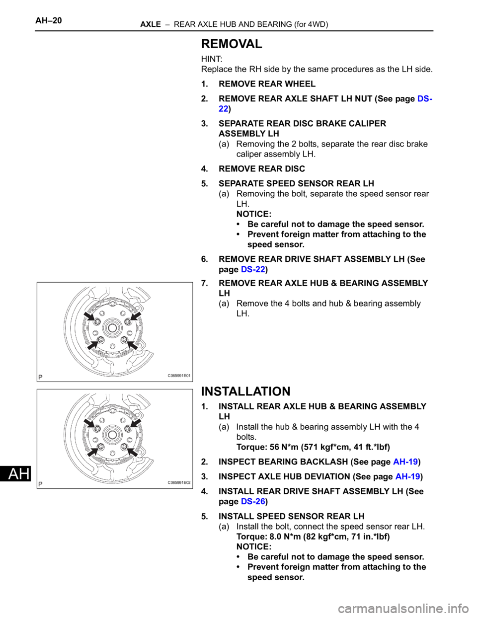
7. REMOVE REAR AXLE HUB & BEARING ASSEMBLY
LH
(a) Remove the 4 bolts and hub & bearing assembly
LH.
INSTALLATION
1. INSTALL REAR AXLE HUB & BEARING ASSEMBLY
LH
(a) Install the hub & bearing assembly LH with the 4
bolts.
Torque: 56 N*m (571 kgf*cm, 41 ft.*lbf)
2. INSPECT BEARING BACKLASH (See page AH-19)
3. INSPECT AXLE HUB DEVIATION (See page AH-19)
4. INSTALL REAR DRIVE SHAFT ASSEMBLY LH (See
page DS-26)
5. INSTALL SPEED SENSOR REAR LH
(a) Install the bolt, connect the speed sensor rear LH.
Torque: 8.0 N*m (82 kgf*cm, 71 in.*lbf)
NOTICE:
• Be careful not to damage the speed sensor.
• Prevent foreign matter from attaching to the
speed sensor.
C065991E01
C065991E02
Page 2162 of 3000
AXLE – REAR AXLE HUB AND BEARING (for 4WD)AH–21
AH
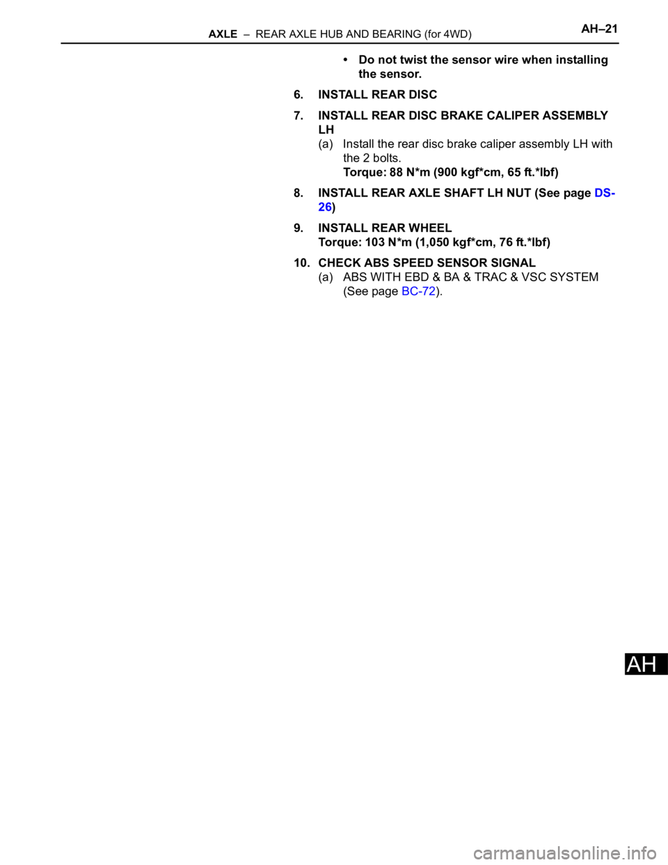
• Do not twist the sensor wire when installing
the sensor.
6. INSTALL REAR DISC
7. INSTALL REAR DISC BRAKE CALIPER ASSEMBLY
LH
(a) Install the rear disc brake caliper assembly LH with
the 2 bolts.
Torque: 88 N*m (900 kgf*cm, 65 ft.*lbf)
8. INSTALL REAR AXLE SHAFT LH NUT (See page DS-
26)
9. INSTALL REAR WHEEL
Torque: 103 N*m (1,050 kgf*cm, 76 ft.*lbf)
10. CHECK ABS SPEED SENSOR SIGNAL
(a) ABS WITH EBD & BA & TRAC & VSC SYSTEM
(See page BC-72).
Page 2174 of 3000
AH–18AXLE – REAR AXLE HUB AND BEARING (for 4WD)
AH
SUSPENSION & AXLE
AXLE
REAR AXLE HUB AND BEARING (for 4WD)
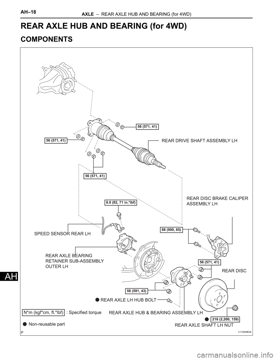
COMPONENTS
C119309E04