Page 2224 of 3000
SUSPENSION – REAR COIL SPRINGSP–41
SP
REMOVAL
1. REMOVE REAR WHEEL
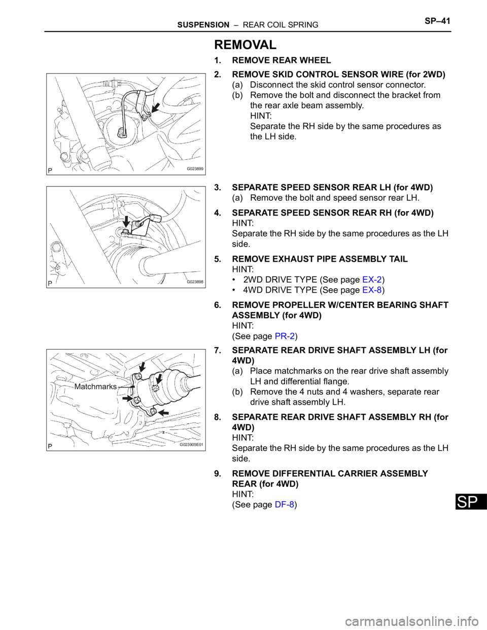
2. REMOVE SKID CONTROL SENSOR WIRE (for 2WD)
(a) Disconnect the skid control sensor connector.
(b) Remove the bolt and disconnect the bracket from
the rear axle beam assembly.
HINT:
Separate the RH side by the same procedures as
the LH side.
3. SEPARATE SPEED SENSOR REAR LH (for 4WD)
(a) Remove the bolt and speed sensor rear LH.
4. SEPARATE SPEED SENSOR REAR RH (for 4WD)
HINT:
Separate the RH side by the same procedures as the LH
side.
5. REMOVE EXHAUST PIPE ASSEMBLY TAIL
HINT:
• 2WD DRIVE TYPE (See page EX-2)
• 4WD DRIVE TYPE (See page EX-8)
6. REMOVE PROPELLER W/CENTER BEARING SHAFT
ASSEMBLY (for 4WD)
HINT:
(See page PR-2)
7. SEPARATE REAR DRIVE SHAFT ASSEMBLY LH (for
4WD)
(a) Place matchmarks on the rear drive shaft assembly
LH and differential flange.
(b) Remove the 4 nuts and 4 washers, separate rear
drive shaft assembly LH.
8. SEPARATE REAR DRIVE SHAFT ASSEMBLY RH (for
4WD)
HINT:
Separate the RH side by the same procedures as the LH
side.
9. REMOVE DIFFERENTIAL CARRIER ASSEMBLY
REAR (for 4WD)
HINT:
(See page DF-8)
G023899
G023898
G023905E01
Page 2229 of 3000
SP–46SUSPENSION – REAR COIL SPRING
SP
(c) Install the bolt.
Torque: 8.0 N*m (82 kgf*cm, 71 in.*lbf)
6. CONNECT REAR BRAKE TUBE NO.1
SST 09023-00101
HINT:
Connect the RH side by the same procedures as the LH
side.
7. INSTALL PARKING BRAKE CABLE ASSEMBLY NO.3
(a) Install the 2 bolts and parking brake cable assembly
No.3 to the rear axle beam assembly.
Torque: 8.0 N*m (82 kgf*cm, 71 in.*lbf)
8. INSTALL PARKING BRAKE CABLE ASSEMBLY NO.2
HINT:
Install the RH side by same procedures as the LH side.
9. INSTALL DIFFERENTIAL CARRIER ASSEMBLY
REAR (for 4WD)
HINT:
(See page DF-8)
10. INSTALL REAR DRIVE SHAFT ASSEMBLY LH (for
4WD)
(a) Install the rear drive shaft assembly LH, 4 washers
and 4 nuts.
Torque: 56 N*m (571 kgf*cm, 41 ft.*lbf)
11. INSTALL REAR DRIVE SHAFT ASSEMBLY RH (for
4WD)
HINT:
Install the RH side by same procedures as the LH side.
12. INSTALL PROPELLER W/CENTER BEARING SHAFT
ASSEMBLY (for 4WD)
HINT:
(See page PR-2)
C088688
G023904
G023905E01
Page 2230 of 3000
SUSPENSION – REAR COIL SPRINGSP–47
SP
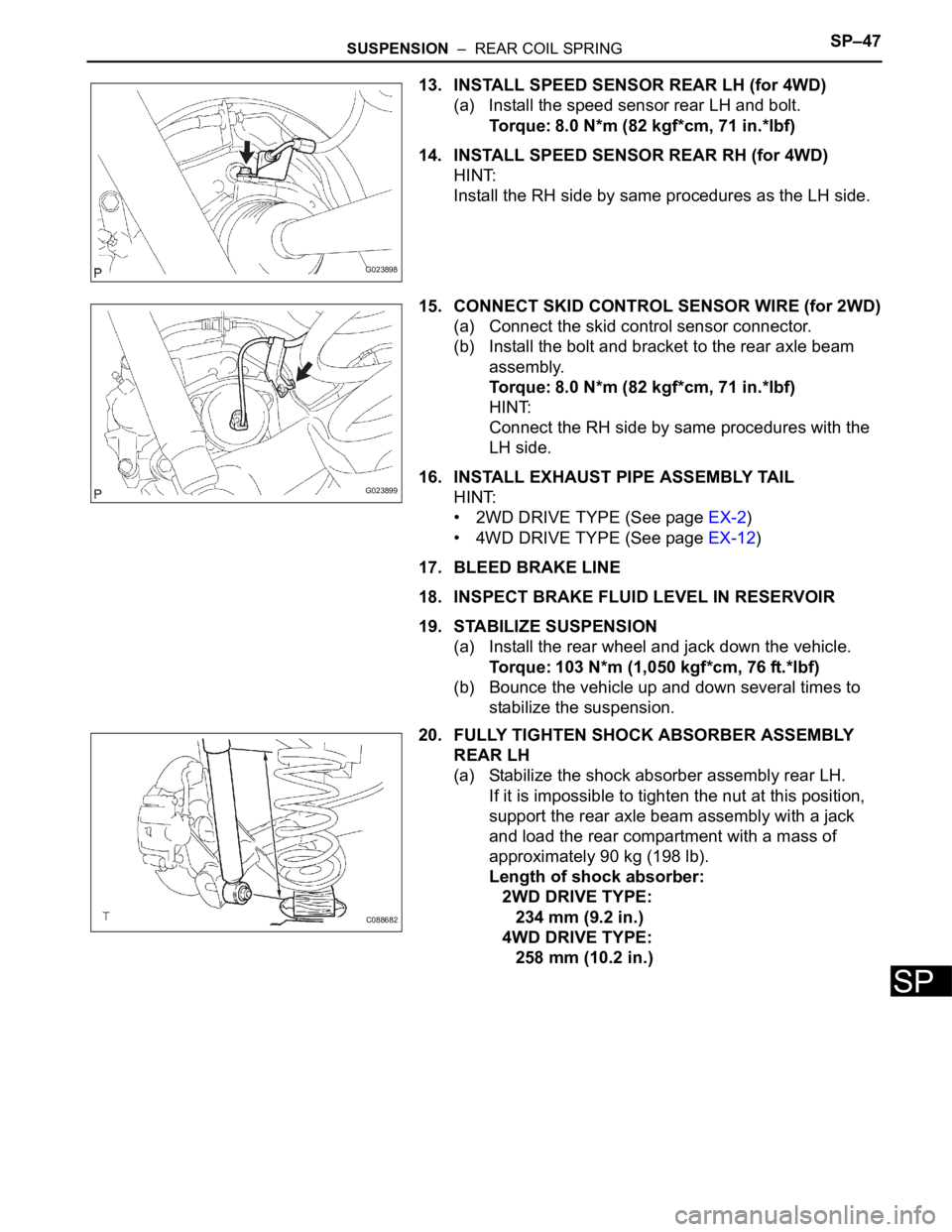
13. INSTALL SPEED SENSOR REAR LH (for 4WD)
(a) Install the speed sensor rear LH and bolt.
Torque: 8.0 N*m (82 kgf*cm, 71 in.*lbf)
14. INSTALL SPEED SENSOR REAR RH (for 4WD)
HINT:
Install the RH side by same procedures as the LH side.
15. CONNECT SKID CONTROL SENSOR WIRE (for 2WD)
(a) Connect the skid control sensor connector.
(b) Install the bolt and bracket to the rear axle beam
assembly.
Torque: 8.0 N*m (82 kgf*cm, 71 in.*lbf)
HINT:
Connect the RH side by same procedures with the
LH side.
16. INSTALL EXHAUST PIPE ASSEMBLY TAIL
HINT:
• 2WD DRIVE TYPE (See page EX-2)
• 4WD DRIVE TYPE (See page EX-12)
17. BLEED BRAKE LINE
18. INSPECT BRAKE FLUID LEVEL IN RESERVOIR
19. STABILIZE SUSPENSION
(a) Install the rear wheel and jack down the vehicle.
Torque: 103 N*m (1,050 kgf*cm, 76 ft.*lbf)
(b) Bounce the vehicle up and down several times to
stabilize the suspension.
20. FULLY TIGHTEN SHOCK ABSORBER ASSEMBLY
REAR LH
(a) Stabilize the shock absorber assembly rear LH.
If it is impossible to tighten the nut at this position,
support the rear axle beam assembly with a jack
and load the rear compartment with a mass of
approximately 90 kg (198 lb).
Length of shock absorber:
2WD DRIVE TYPE:
234 mm (9.2 in.)
4WD DRIVE TYPE:
258 mm (10.2 in.)
G023898
G023899
C088682
Page 2235 of 3000
SUSPENSION – REAR AXLE BEAMSP–57
SP
REMOVAL
1. REMOVE REAR WHEEL
2. REMOVE SKID CONTROL SENSOR WIRE (for 2WD)
HINT:
(See page SP-38)
HINT:
Disconnect the RH side by the same procedures as the
LH side.
3. SEPARATE SPEED SENSOR REAR LH (for 4WD)
HINT:
(See page SP-38)
4. SEPARATE SPEED SENSOR REAR RH (for 4WD)
HINT:
Separate the RH side by the same procedures as the LH
side.
5. REMOVE EXHAUST PIPE ASSEMBLY TAIL
HINT:
• 2WD DRIVE TYPE (See page EX-2)
• 4WD DRIVE TYPE (See page EX-8)
6. REMOVE PROPELLER W/CENTER BEARING SHAFT
ASSEMBLY (for 4WD)
HINT:
(See page PR-2)
7. REMOVE REAR AXLE SHAFT LH NUT (for 4WD)
HINT:
(See page AH-18)
8. REMOVE REAR AXLE SHAFT RH NUT (for 4WD)
HINT:
Remove the RH side by the same procedures as the LH
side.
9. REMOVE REAR DRIVE SHAFT ASSEMBLY LH (for
4WD)
HINT:
(See page AH-18)
10. REMOVE REAR DRIVE SHAFT ASSEMBLY RH (for
4WD)
HINT:
Remove the RH side by the same procedures as the LH
side.
11. REMOVE DIFFERENTIAL CARRIER ASSEMBLY
REAR (for 4WD)
HINT:
(See page DF-8)
12. SEPARATE PARKING BRAKE CABLE ASSEMBLY
NO.3
HINT:
(See page SP-38)
Page 2237 of 3000
SUSPENSION – REAR AXLE BEAMSP–59
SP
25. REMOVE REAR AXLE HUB & BEARING ASSEMBLY
RH (for 2WD)
HINT:
Remove the RH side by the same procedures as the LH
side.
26. REMOVE REAR AXLE HUB & BEARING ASSEMBLY
LH (for 4WD)
HINT:
(See page AH-18)
27. REMOVE REAR AXLE HUB & BEARING ASSEMBLY
RH (for 4WD)
HINT:
Remove the RH side by the same procedures as the LH
side.
28. REMOVE PARKING BRAKE PLATE SUB-ASSEMBLY
LH (for DISC REAR BRAKE)
(a) 2WD DRIVE TYPE: Remove the rear axle bearing
retainer inner LH and parking brake plate sub-
assembly LH.
(b) 4WD DRIVE TYPE: Remove the rear axle bearing
retainer outer and parking brake plate sub-assembly
LH.
29. REMOVE PARKING BRAKE PLATE SUB-ASSEMBLY
RH (for DISC REAR BRAKE)
HINT:
Remove the RH side by the same procedures as the LH
side.
30. REMOVE BRAKE BACKING PLATE SUB-ASSEMBLY
LH (DRUM REAR BRAKE)
(a) Remove the 2 rear axle bearing retainer inner LH
and parking brake plate sub-assembly LH.
31. REMOVE BRAKE BACKING PLATE SUB-ASSEMBLY
RH (for DRUM REAR BRAKE)
HINT:
Remove the RH side by the same procedures as the LH
side.
32. SEPARATE SHOCK ABSORBER ASSEMBLY REAR
LH
HINT:
(See page SP-38)
33. SEPARATE SHOCK ABSORBER ASSEMBLY REAR
RH
HINT:
Separate the RH side by the same procedures as the LH
side.
34. REMOVE COIL SPRING REAR LH
HINT:
(See page SP-38)
Page 2242 of 3000
SP–54SUSPENSION – REAR SHOCK ABSORBER
SP
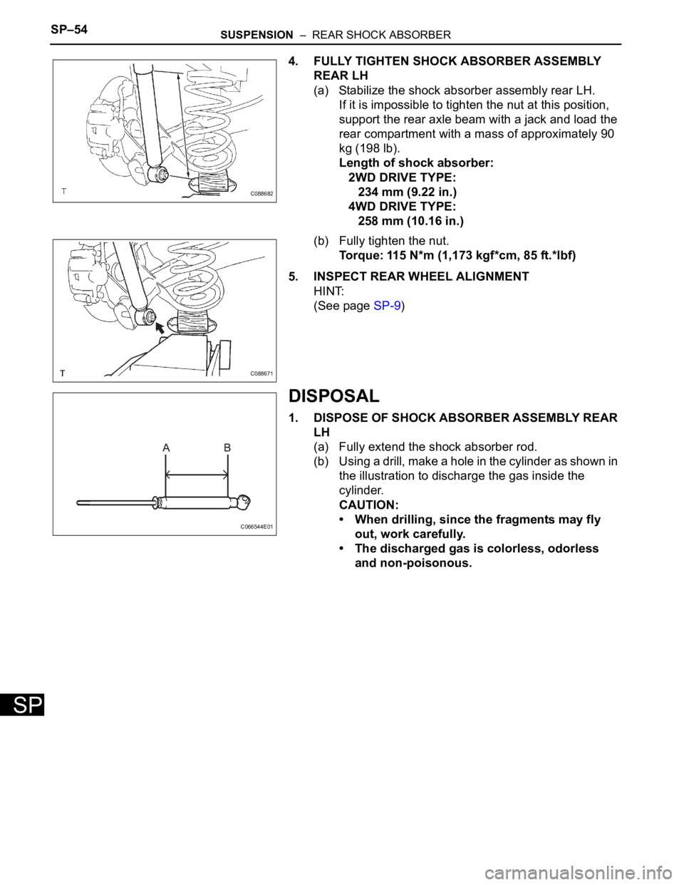
4. FULLY TIGHTEN SHOCK ABSORBER ASSEMBLY
REAR LH
(a) Stabilize the shock absorber assembly rear LH.
If it is impossible to tighten the nut at this position,
support the rear axle beam with a jack and load the
rear compartment with a mass of approximately 90
kg (198 lb).
Length of shock absorber:
2WD DRIVE TYPE:
234 mm (9.22 in.)
4WD DRIVE TYPE:
258 mm (10.16 in.)
(b) Fully tighten the nut.
Torque: 115 N*m (1,173 kgf*cm, 85 ft.*lbf)
5. INSPECT REAR WHEEL ALIGNMENT
HINT:
(See page SP-9)
DISPOSAL
1. DISPOSE OF SHOCK ABSORBER ASSEMBLY REAR
LH
(a) Fully extend the shock absorber rod.
(b) Using a drill, make a hole in the cylinder as shown in
the illustration to discharge the gas inside the
cylinder.
CAUTION:
• When drilling, since the fragments may fly
out, work carefully.
• The discharged gas is colorless, odorless
and non-poisonous.
C088682
C088671
C066544E01
Page 2244 of 3000
SP–62SUSPENSION – REAR AXLE BEAM
SP
9. CONNECT SHOCK ABSORBER ASSEMBLY REAR
RH
HINT:
Connect the RH side by the same procedures as the LH
side.
10. INSTALL BRAKE BACKING PLATE SUB-ASSEMBLY
REAR LH (for DRUM REAR BRAKE)
(a) Install the 2 rear axle bearing retainer inner LH and
parking brake plate sub-assembly LH.
11. INSTALL BRAKE BACKING PLATE SUB-ASSEMBLY
REAR RH (for DRUM REAR BRAKE)
HINT:
Install the RH side by the same procedures as the LH
side.
12. INSTALL PARKING BRAKE PLATE SUB-ASSEMBLY
LH (for DISC REAR BRAKE)
(a) 2WD DRIVE TYPE: Install the 2 rear axle bearing
retainer inner LH and parking brake plate sub-
assembly LH to the rear axle beam assembly.
(b) 4WD DRIVE TYPE: Install the rear axle bearing
retainer outer and parking brake plate sub-assembly
LH to the rear axle beam assembly.
13. INSTALL PARKING BRAKE PLATE SUB-ASSEMBLY
RH (for DISC REAR BRAKE)
HINT:
Install the RH side by the same procedures as the LH
side.
14. INSTALL REAR AXLE HUB & BEARING ASSEMBLY
LH (for 2WD)
HINT:
(See page AH-15)
15. INSTALL REAR AXLE HUB & BEARING ASSEMBLY
RH (for 2WD)
HINT:
Install the RH side by the same procedures as the LH
side.
16. INSTALL REAR AXLE HUB & BEARING ASSEMBLY
LH (for 4WD)
HINT:
(See page AH-18)
17. INSTALL REAR AXLE HUB & BEARING ASSEMBLY
RH (for 4WD)
HINT:
Install the RH side by the same procedures as the LH
side.
18. INSTALL REAR BRAKE DRUM SUB-ASSEMBLY (for
DRUM REAR BRAKE)
19. INSTALL REAR DISC (for DISC REAR BRAKE)
Page 2245 of 3000
SUSPENSION – REAR AXLE BEAMSP–63
SP
20. INSTALL REAR DISC BRAKE CALIPER ASSEMBLY
LH (for DISC REAR BRAKE)
(a) Install the 2 bolts and rear disc brake caliper
assembly LH to the rear axle beam assembly.
Torque: 88 N*m (897 kgf*cm, 65 ft.*lbf)
21. INSTALL REAR DISC BRAKE CALIPER ASSEMBLY
RH (for DISC REAR BRAKE)
HINT:
Install the RH side by the same procedures as the LH
side.
22. CONNECT REAR BRAKE TUBE NO.2
HINT:
(See page SP-38)
SST 09023-00101
23. CONNECT REAR BRAKE TUBE NO.1
SST 09023-00101
HINT:
Connect the RH side by the same procedures as the LH
side.
24. INSTALL PARKING BRAKE CABLE ASSEMBLY NO.3
HINT:
(See page SP-38)
25. INSTALL PARKING BRAKE CABLE ASSEMBLY NO.2
HINT:
Install the RH side by the same procedures as the LH
side.
26. INSTALL DIFFERENTIAL CARRIER ASSEMBLY
REAR (for 4WD)
HINT:
(See page DF-8)
27. INSTALL REAR DRIVE SHAFT ASSEMBLY LH (for
4WD)
HINT:
(See page AH-18)
28. INSTALL REAR DRIVE SHAFT ASSEMBLY RH (for
4WD)
HINT:
Install the RH side by the same procedures as the LH
side.
29. INSTALL REAR AXLE SHAFT LH NUT (for 4WD)
HINT:
(See page AH-18)
30. INSTALL REAR AXLE SHAFT RH NUT (for 4WD)
HINT:
Install the RH side by the same procedures as the LH
side.
31. INSTALL PROPELLER W/CENTER BEARING SHAFT
ASSEMBLY (for 4WD)