Page 117 of 3000
DS–12DRIVE SHAFT – FRONT DRIVE SHAFT
DS
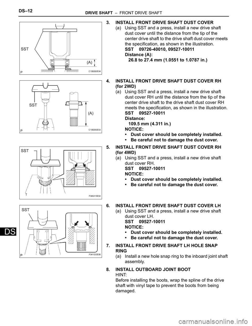
3. INSTALL FRONT DRIVE SHAFT DUST COVER
(a) Using SST and a press, install a new drive shaft
dust cover until the distance from the tip of the
center drive shaft to the drive shaft dust cover meets
the specification, as shown in the illustration.
SST 09726-40010, 09527-10011
Distance (A):
26.8 to 27.4 mm (1.0551 to 1.0787 in.)
4. INSTALL FRONT DRIVE SHAFT DUST COVER RH
(for 2WD)
(a) Using SST and a press, install a new drive shaft
dust cover RH until the distance from the tip of the
center drive shaft to the drive shaft dust cover RH
meets the specification, as shown in the illustration.
SST 09527-10011
Distance:
109.5 mm (4.311 in.)
NOTICE:
• Dust cover should be completely installed.
• Be careful not to damage the dust cover.
5. INSTALL FRONT DRIVE SHAFT DUST COVER RH
(for 4WD)
(a) Using SST and a press, install a new drive shaft
dust cover RH.
SST 09527-10011
NOTICE:
• Dust cover should be completely installed.
• Be careful not to damage the dust cover.
6. INSTALL FRONT DRIVE SHAFT DUST COVER LH
(a) Using SST and a press, install a new drive shaft
dust cover LH.
SST 09527-10011
NOTICE:
• Dust cover should be completely installed.
• Be careful not to damage the dust cover.
7. INSTALL FRONT DRIVE SHAFT LH HOLE SNAP
RING
(a) Install a new hole snap ring to the inboard joint shaft
assembly.
8. INSTALL OUTBOARD JOINT BOOT
HINT:
Before installing the boots, wrap the spline of the drive
shaft with vinyl tape to prevent the boots from being
damaged.
C108282E04
C108283E03
F040215E02
F041033E06
Page 118 of 3000
DRIVE SHAFT – FRONT DRIVE SHAFTDS–13
DS
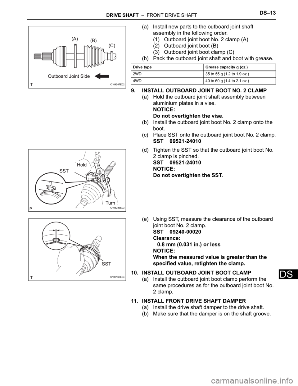
(a) Install new parts to the outboard joint shaft
assembly in the following order.
(1) Outboard joint boot No. 2 clamp (A)
(2) Outboard joint boot (B)
(3) Outboard joint boot clamp (C)
(b) Pack the outboard joint shaft and boot with grease.
9. INSTALL OUTBOARD JOINT BOOT NO. 2 CLAMP
(a) Hold the outboard joint shaft assembly between
aluminium plates in a vise.
NOTICE:
Do not overtighten the vise.
(b) Install the outboard joint boot No. 2 clamp onto the
boot.
(c) Place SST onto the outboard joint boot No. 2 clamp.
SST 09521-24010
(d) Tighten the SST so that the outboard joint boot No.
2 clamp is pinched.
SST 09521-24010
NOTICE:
Do not overtighten the SST.
(e) Using SST, measure the clearance of the outboard
joint boot No. 2 clamp.
SST 09240-00020
Clearance:
0.8 mm (0.031 in.) or less
NOTICE:
When the measured value is greater than the
specified value, retighten the clamp.
10. INSTALL OUTBOARD JOINT BOOT CLAMP
(a) Install the outboard joint boot clamp perform the
same procedures as for the outboard joint boot No.
2 clamp.
11. INSTALL FRONT DRIVE SHAFT DAMPER
(a) Install the drive shaft damper to the drive shaft.
(b) Make sure that the damper is on the shaft groove.
C104547E02
Drive type Grease capacity g (oz.)
2WD 35 to 55 g (1.2 to 1.9 oz.)
4WD 40 to 60 g (1.4 to 2.1 oz.)
C108286E03
C106165E04
Page 120 of 3000
DRIVE SHAFT – FRONT DRIVE SHAFTDS–15
DS
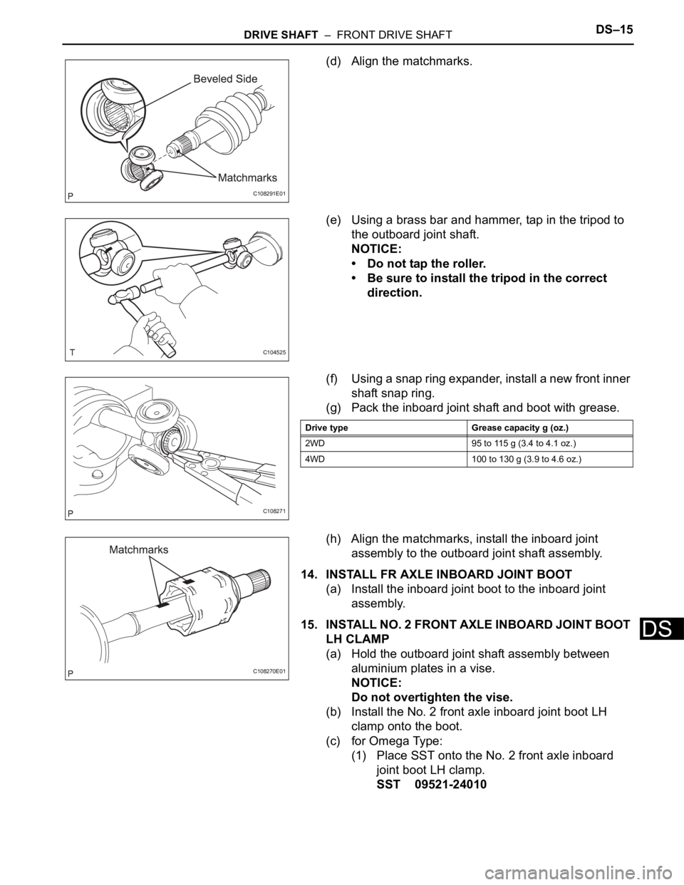
(d) Align the matchmarks.
(e) Using a brass bar and hammer, tap in the tripod to
the outboard joint shaft.
NOTICE:
• Do not tap the roller.
• Be sure to install the tripod in the correct
direction.
(f) Using a snap ring expander, install a new front inner
shaft snap ring.
(g) Pack the inboard joint shaft and boot with grease.
(h) Align the matchmarks, install the inboard joint
assembly to the outboard joint shaft assembly.
14. INSTALL FR AXLE INBOARD JOINT BOOT
(a) Install the inboard joint boot to the inboard joint
assembly.
15. INSTALL NO. 2 FRONT AXLE INBOARD JOINT BOOT
LH CLAMP
(a) Hold the outboard joint shaft assembly between
aluminium plates in a vise.
NOTICE:
Do not overtighten the vise.
(b) Install the No. 2 front axle inboard joint boot LH
clamp onto the boot.
(c) for Omega Type:
(1) Place SST onto the No. 2 front axle inboard
joint boot LH clamp.
SST 09521-24010
C108291E01
C104525
C108271
Drive type Grease capacity g (oz.)
2WD 95 to 115 g (3.4 to 4.1 oz.)
4WD 100 to 130 g (3.9 to 4.6 oz.)
C108270E01
Page 122 of 3000
DRIVE SHAFT – FRONT DRIVE SHAFTDS–17
DS
(d) Check the boots for damage.
HINT:
For dimension (A), refer to the following table.
F045048E04
DRIVE TYPE LH mm (in.) RH mm (in.)
2WD638.40 +- 5.0 (25.1338 +-
0.20)957.00 +- 5.0 (37.6771 +-
0.20)
4WD553.64 +- 5.0 (21.7968 +-
0.20)992.24 +- 5.0 (39.0645 +-
0.20)
Page 168 of 3000
SUSPENSION – SUSPENSION SYSTEMSP–3
SP
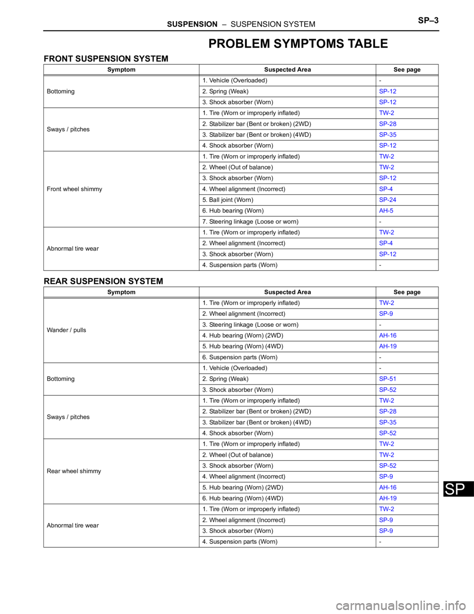
PROBLEM SYMPTOMS TABLE
FRONT SUSPENSION SYSTEM
REAR SUSPENSION SYSTEM
Symptom Suspected Area See page
Bottoming1. Vehicle (Overloaded) -
2. Spring (Weak)SP-12
3. Shock absorber (Worn)SP-12
Sways / pitches1. Tire (Worn or improperly inflated)TW-2
2. Stabilizer bar (Bent or broken) (2WD)SP-28
3. Stabilizer bar (Bent or broken) (4WD)SP-35
4. Shock absorber (Worn)SP-12
Front wheel shimmy1. Tire (Worn or improperly inflated)TW-2
2. Wheel (Out of balance)TW-2
3. Shock absorber (Worn)SP-12
4. Wheel alignment (Incorrect)SP-4
5. Ball joint (Worn)SP-24
6. Hub bearing (Worn)AH-5
7. Steering linkage (Loose or worn) -
Abnormal tire wear1. Tire (Worn or improperly inflated)TW-2
2. Wheel alignment (Incorrect)SP-4
3. Shock absorber (Worn)SP-12
4. Suspension parts (Worn) -
Symptom Suspected Area See page
Wander / pulls1. Tire (Worn or improperly inflated)TW-2
2. Wheel alignment (Incorrect)SP-9
3. Steering linkage (Loose or worn) -
4. Hub bearing (Worn) (2WD)AH-16
5. Hub bearing (Worn) (4WD)AH-19
6. Suspension parts (Worn) -
Bottoming1. Vehicle (Overloaded) -
2. Spring (Weak)SP-51
3. Shock absorber (Worn)SP-52
Sways / pitches1. Tire (Worn or improperly inflated)TW-2
2. Stabilizer bar (Bent or broken) (2WD)SP-28
3. Stabilizer bar (Bent or broken) (4WD)SP-35
4. Shock absorber (Worn)SP-52
Rear wheel shimmy1. Tire (Worn or improperly inflated)TW-2
2. Wheel (Out of balance)TW-2
3. Shock absorber (Worn)SP-52
4. Wheel alignment (Incorrect)SP-9
5. Hub bearing (Worn) (2WD)AH-16
6. Hub bearing (Worn) (4WD)AH-19
Abnormal tire wear1. Tire (Worn or improperly inflated)TW-2
2. Wheel alignment (Incorrect)SP-9
3. Shock absorber (Worn)SP-9
4. Suspension parts (Worn) -
Page 172 of 3000
SP–54SUSPENSION – REAR SHOCK ABSORBER
SP
4. FULLY TIGHTEN SHOCK ABSORBER ASSEMBLY
REAR LH
(a) Stabilize the shock absorber assembly rear LH.
If it is impossible to tighten the nut at this position,
support the rear axle beam with a jack and load the
rear compartment with a mass of approximately 90
kg (198 lb).
Length of shock absorber:
2WD DRIVE TYPE:
234 mm (9.22 in.)
4WD DRIVE TYPE:
258 mm (10.16 in.)
(b) Fully tighten the nut.
Torque: 115 N*m (1,173 kgf*cm, 85 ft.*lbf)
5. INSPECT REAR WHEEL ALIGNMENT
HINT:
(See page SP-9)
DISPOSAL
1. DISPOSE OF SHOCK ABSORBER ASSEMBLY REAR
LH
(a) Fully extend the shock absorber rod.
(b) Using a drill, make a hole in the cylinder as shown in
the illustration to discharge the gas inside the
cylinder.
CAUTION:
• When drilling, since the fragments may fly
out, work carefully.
• The discharged gas is colorless, odorless
and non-poisonous.
C088682
C088671
C066544E01
Page 174 of 3000
TW–4TIRE AND WHEEL – TIRE AND WHEEL SYSTEM
TW
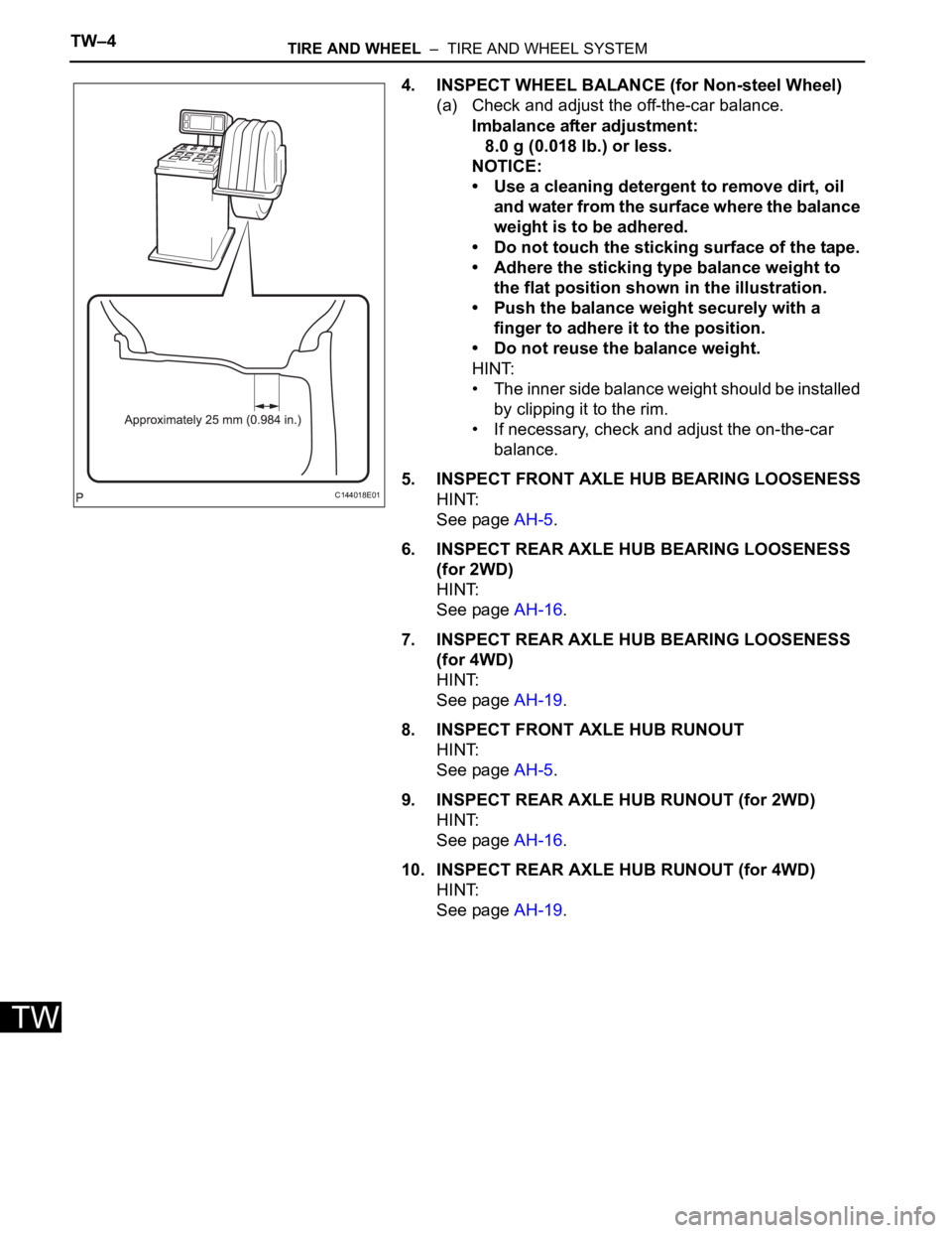
4. INSPECT WHEEL BALANCE (for Non-steel Wheel)
(a) Check and adjust the off-the-car balance.
Imbalance after adjustment:
8.0 g (0.018 lb.) or less.
NOTICE:
• Use a cleaning detergent to remove dirt, oil
and water from the surface where the balance
weight is to be adhered.
• Do not touch the sticking surface of the tape.
• Adhere the sticking type balance weight to
the flat position shown in the illustration.
• Push the balance weight securely with a
finger to adhere it to the position.
• Do not reuse the balance weight.
HINT:
• The inner side balance weight should be installed
by clipping it to the rim.
• If necessary, check and adjust the on-the-car
balance.
5. INSPECT FRONT AXLE HUB BEARING LOOSENESS
HINT:
See page AH-5.
6. INSPECT REAR AXLE HUB BEARING LOOSENESS
(for 2WD)
HINT:
See page AH-16.
7. INSPECT REAR AXLE HUB BEARING LOOSENESS
(for 4WD)
HINT:
See page AH-19.
8. INSPECT FRONT AXLE HUB RUNOUT
HINT:
See page AH-5.
9. INSPECT REAR AXLE HUB RUNOUT (for 2WD)
HINT:
See page AH-16.
10. INSPECT REAR AXLE HUB RUNOUT (for 4WD)
HINT:
See page AH-19.
C144018E01
Page 418 of 3000
ES–1122GR-FE ENGINE CONTROL SYSTEM – SFI SYSTEM
ES
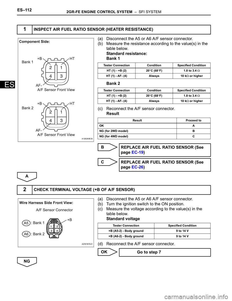
(a) Disconnect the A5 or A6 A/F sensor connector.
(b) Measure the resistance according to the value(s) in the
table below.
Standard resistance:
Bank 1
Bank 2
(c) Reconnect the A/F sensor connector.
Result
B
C
A
(a) Disconnect the A5 or A6 A/F sensor connector.
(b) Turn the ignition switch to the ON position.
(c) Measure the voltage according to the value(s) in the
table below.
Standard voltage
(d) Reconnect the A/F sensor connector.
OK
NG
1INSPECT AIR FUEL RATIO SENSOR (HEATER RESISTANCE)
A126269E35
Tester Connection Condition Specified Condition
HT (1) - +B (2) 20
C (68F) 1.8 to 3.4
HT (1) - AF- (4) Always 10 k or higher
Tester Connection Condition Specified Condition
HT (1) - +B (2) 20
C (68F) 1.8 to 3.4
HT (1) - AF- (4) Always 10 k or higher
Result Proceed to
OK A
NG (for 2WD model) B
NG (for 4WD model) C
REPLACE AIR FUEL RATIO SENSOR (See
page EC-19)
REPLACE AIR FUEL RATIO SENSOR (See
page EC-26)
2CHECK TERMINAL VOLTAGE (+B OF A/F SENSOR)
A076787E21
Tester Connection Specified Condition
+B (A5-2) - Body ground 9 to 14 V
+B (A6-2) - Body ground 9 to 14 V
Go to step 7