Page 667 of 3000

ES–3742GR-FE ENGINE CONTROL SYSTEM – SFI SYSTEM
ES
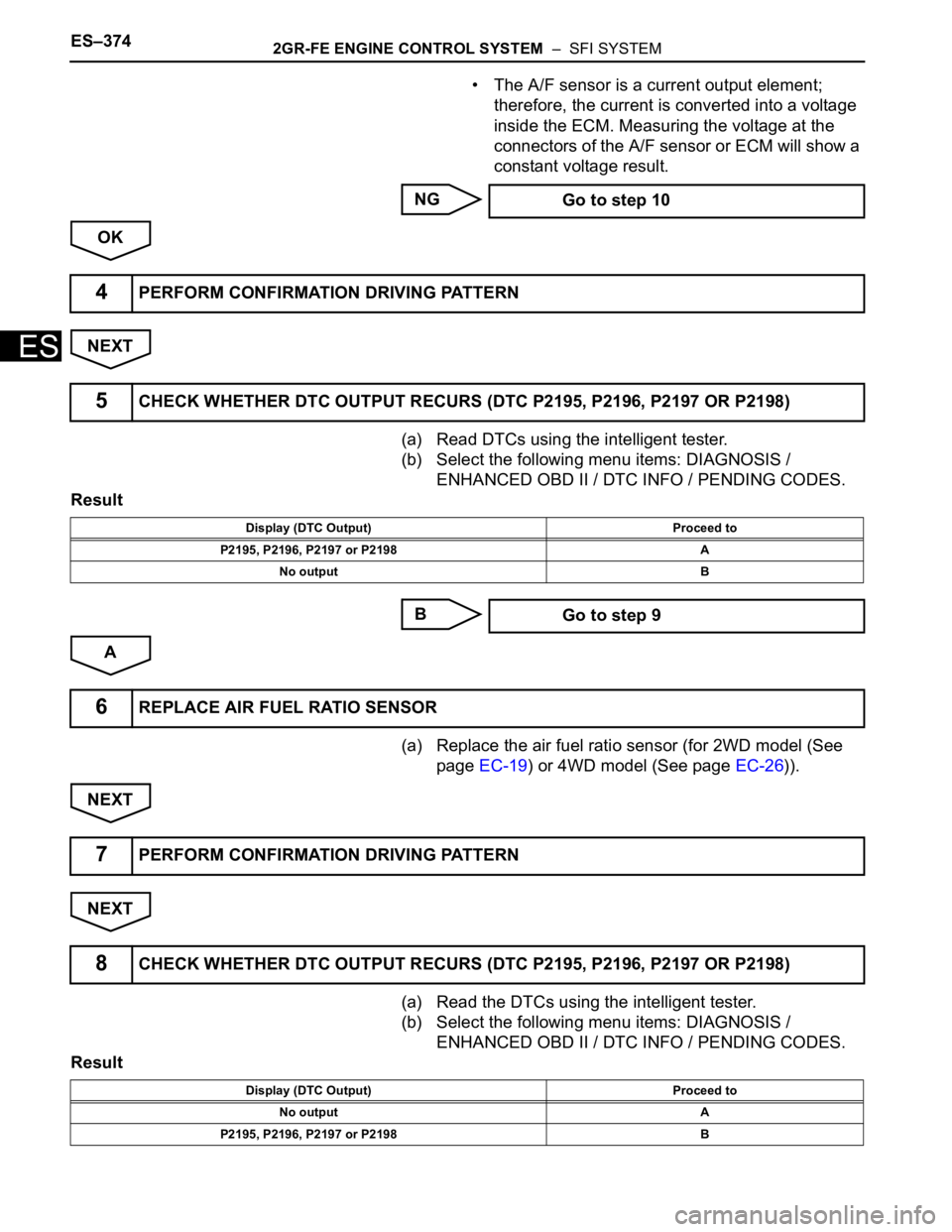
• The A/F sensor is a current output element;
therefore, the current is converted into a voltage
inside the ECM. Measuring the voltage at the
connectors of the A/F sensor or ECM will show a
constant voltage result.
NG
OK
NEXT
(a) Read DTCs using the intelligent tester.
(b) Select the following menu items: DIAGNOSIS /
ENHANCED OBD II / DTC INFO / PENDING CODES.
Result
B
A
(a) Replace the air fuel ratio sensor (for 2WD model (See
page EC-19) or 4WD model (See page EC-26)).
NEXT
NEXT
(a) Read the DTCs using the intelligent tester.
(b) Select the following menu items: DIAGNOSIS /
ENHANCED OBD II / DTC INFO / PENDING CODES.
Result Go to step 10
4PERFORM CONFIRMATION DRIVING PATTERN
5CHECK WHETHER DTC OUTPUT RECURS (DTC P2195, P2196, P2197 OR P2198)
Display (DTC Output) Proceed to
P2195, P2196, P2197 or P2198 A
No output B
Go to step 9
6REPLACE AIR FUEL RATIO SENSOR
7PERFORM CONFIRMATION DRIVING PATTERN
8CHECK WHETHER DTC OUTPUT RECURS (DTC P2195, P2196, P2197 OR P2198)
Display (DTC Output) Proceed to
No output A
P2195, P2196, P2197 or P2198 B
Page 668 of 3000
2GR-FE ENGINE CONTROL SYSTEM – SFI SYSTEMES–375
ES
B
A
(a) Has the vehicle run out of fuel in the past?.
NO
YES
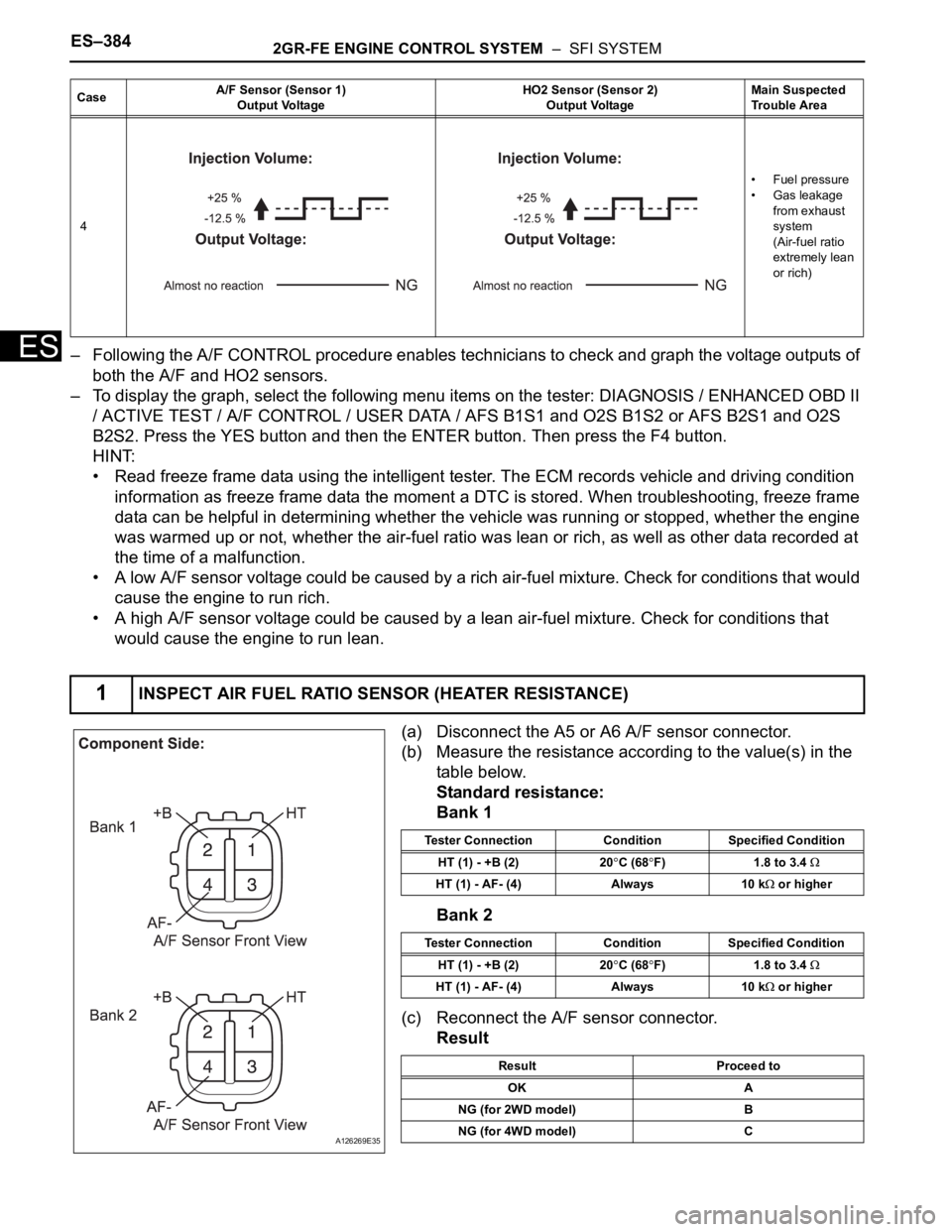
(a) Disconnect the A5 or A6 A/F sensor connector.
(b) Measure the resistance according to the value(s) in the
table below.
Standard resistance:
Bank 1
Bank 2
(c) Reconnect the A/F sensor connector.
Result
B
C
AREPLACE ECM
9CONFIRM WHETHER VEHICLE HAS RUN OUT OF FUEL IN PAST
CHECK FOR INTERMITTENT PROBLEMS
DTC CAUSED BY RUNNING OUT OF FUEL
10INSPECT AIR FUEL RATIO SENSOR (HEATER RESISTANCE)
A126269E35
Tester Connection Specified Condition
HT (1) - +B (2) 1.8 to 3.4
at 20C (68F)
HT (1) - AF- (4) 10 k
or higher
Tester Connection Specified Condition
HT (1) - +B (2) 1.8 to 3.4
at 20C (68F)
HT (1) - AF- (4) 10 k
or higher
Result Proceed to
OK A
NG (for 2WD model) B
NG (for 4WD model) C
REPLACE AIR FUEL RATIO SENSOR (See
page EC-19)
REPLACE AIR FUEL RATIO SENSOR (See
page EC-26)
Page 671 of 3000
ES–3782GR-FE ENGINE CONTROL SYSTEM – SFI SYSTEM
ES
NG
OK
(a) Replace the air fuel ratio sensor (for 2WD model (See
page EC-19) or 4WD model (See page EC-26)).
NEXT
NEXT
(a) Read the DTCs using the intelligent tester.
(b) Select the following menu items: DIAGNOSIS /
ENHANCED OBD II / DTC INFO / PENDING CODES.
Result
B
A
(a) Has the vehicle run out of fuel in the past?.
NO
YES
(a) Replace the air fuel ratio sensor (for 2WD model (See
page EC-19) or 4WD model (See page EC-26)).
NEXTREPLACE FUEL INJECTOR ASSEMBLY (See
page FU-13)
16REPLACE AIR FUEL RATIO SENSOR
17PERFORM CONFIRMATION DRIVING PATTERN
18CHECK WHETHER DTC OUTPUT RECURS (DTC P2195, P2196, P2197 OR P2198)
Display (DTC Output) Proceed to
No output A
P2195, P2196, P2197 or P2198 B
REPLACE ECM AND PERFORM
CONFIRMATION DRIVING PATTERN
19CONFIRM WHETHER VEHICLE HAS RUN OUT OF FUEL IN PAST
CHECK FOR INTERMITTENT PROBLEMS
DTC CAUSED BY RUNNING OUT OF FUEL
20REPLACE AIR FUEL RATIO SENSOR
Page 677 of 3000

ES–3842GR-FE ENGINE CONTROL SYSTEM – SFI SYSTEM
ES– Following the A/F CONTROL procedure enables technicians to check and graph the voltage outputs of
both the A/F and HO2 sensors.
– To display the graph, select the following menu items on the tester: DIAGNOSIS / ENHANCED OBD II
/ ACTIVE TEST / A/F CONTROL / USER DATA / AFS B1S1 and O2S B1S2 or AFS B2S1 and O2S
B2S2. Press the YES button and then the ENTER button. Then press the F4 button.
HINT:
• Read freeze frame data using the intelligent tester. The ECM records vehicle and driving condition
information as freeze frame data the moment a DTC is stored. When troubleshooting, freeze frame
data can be helpful in determining whether the vehicle was running or stopped, whether the engine
was warmed up or not, whether the air-fuel ratio was lean or rich, as well as other data recorded at
the time of a malfunction.
• A low A/F sensor voltage could be caused by a rich air-fuel mixture. Check for conditions that would
cause the engine to run rich.
• A high A/F sensor voltage could be caused by a lean air-fuel mixture. Check for conditions that
would cause the engine to run lean.
(a) Disconnect the A5 or A6 A/F sensor connector.
(b) Measure the resistance according to the value(s) in the
table below.
Standard resistance:
Bank 1
Bank 2
(c) Reconnect the A/F sensor connector.
Result
4•Fuel pressure
• Gas leakage
from exhaust
system
(Air-fuel ratio
extremely lean
or rich)
1INSPECT AIR FUEL RATIO SENSOR (HEATER RESISTANCE)
CaseA/F Sensor (Sensor 1)
Output VoltageHO2 Sensor (Sensor 2)
Output VoltageMain Suspected
Trouble Area
A126269E35
Tester Connection Condition Specified Condition
HT (1) - +B (2) 20
C (68F) 1.8 to 3.4
HT (1) - AF- (4) Always 10 k or higher
Tester Connection Condition Specified Condition
HT (1) - +B (2) 20
C (68F) 1.8 to 3.4
HT (1) - AF- (4) Always 10 k or higher
Result Proceed to
OK A
NG (for 2WD model) B
NG (for 4WD model) C
Page 694 of 3000
2GR-FE ENGINE CONTROL SYSTEM – SFI SYSTEMES–401
ES
(a) Disconnect the A5 or A6 A/F sensor connector.
(b) Measure the resistance according to the value(s) in the
table below.
Standard resistance:
Bank 1
Bank 2
(c) Reconnect the A/F sensor connector.
Result
B
C
A
2INSPECT AIR FUEL RATIO SENSOR (HEATER RESISTANCE)
A126269E35
Tester Connection Specified Condition
HT (1) - +B (2) 1.8 to 3.4
at 20C (68F)
HT (1) - AF- (4) 10 k
or higher
Tester Connection Specified Condition
HT (1) - +B (2) 1.8 to 3.4
at 20C (68F)
HT (1) - AF- (4) 10 k
or higher
Result Proceed to
OK A
NG (for 2WD model) B
NG (for 4WD model) C
REPLACE AIR FUEL RATIO SENSOR (See
page EC-19)
REPLACE AIR FUEL RATIO SENSOR (See
page EC-26)
Page 696 of 3000
2GR-FE ENGINE CONTROL SYSTEM – SFI SYSTEMES–403
ES
NG
OK
NEXT
(a) Read the DTCs using the intelligent tester.
(b) Select the following menu items: DIAGNOSIS /
ENHANCED OBD II / DTC INFO / PENDING CODES.
Result
B
A
(a) Replace the air fuel ratio sensor (for 2WD model (See
page EC-19) or 4WD model (See page EC-26)).
A165205E01
REPAIR OR REPLACE HARNESS OR
CONNECTOR (A/F SENSOR - ECM)
4PERFORM CONFIRMATION DRIVING PATTERN
5CHECK WHETHER DTC OUTPUT RECURS (DTC P2A00 AND/OR P2A03)
Display (DTC Output) Proceed to
P2A00 and/or P2A03 A
No output B
CHECK FOR INTERMITTENT PROBLEMS
6REPLACE AIR FUEL RATIO SENSOR
Page 864 of 3000
2GR-FE ENGINE MECHANICAL – ENGINE ASSEMBLYEM–47
EM
13. INSTALL ENGINE MOUNTING BRACKET RR (for
4WD)
(a) Install the engine mounting bracket RR with the 3
bolts.
Torque: 64 N*m (650 kgf*cm, 47 ft.*lbf)
14. INSTALL DRIVE SHAFT BEARING BRACKET (for
2WD)
(a) Install the drive shaft bearing bracket with the 3
bolts.
Torque: 64 N*m (650 kgf*cm, 47 ft.*lbf)
15. INSTALL ENGINE MOUNTING BRACKET RH
(a) Install the engine mounting bracket RH with the 3
bolts.
Torque: 54 N*m (551 kgf*cm, 40 ft.*lbf)
16. INSTALL EXHAUST MANIFOLD SUB-ASSEMBLY LH
(a) Install a new gasket as shown in the illustration.
A143881
A163583
A129642
A129649E01
Page 867 of 3000
EM–502GR-FE ENGINE MECHANICAL – ENGINE ASSEMBLY
EM
(d) Connect the connector.
(e) Connect the No. 1 ventilation hose.
(f) Install the clamp and connect the throttle with motor
body assembly connector.
(g) Connect the vapor feed hose.
(h) Connect the 2 water by-pass hoses to the throttle
with motor body assembly.
25. INSTALL VENTILATION HOSE
(a) Using pliers, grip the claws of the 2 clips and slide
the 2 clips to the intake air surge tank assembly and
ventilation valve.
26. INSTALL ENGINE HANGERS
(a) Install the 4 bolts, and 2 engine hangers.
27. REMOVE ENGINE STAND
28. INSTALL DRIVE PLATE AND RING GEAR SUB-
ASSEMBLY (See page EM-13)
29. INSTALL AUTOMATIC TRANSAXLE ASSEMBLY (for
2WD)
HINT:
See page AX-166.
30. INSTALL AUTOMATIC TRANSAXLE ASSEMBLY (for
4WD)
HINT:
(See page AX-167).
31. INSTALL TRANSFER STIFFENER PLATE RH (See
page AX-168)
A129467
A129464E04
A162372
A129635E01