Page 971 of 3000
EM–1622GR-FE ENGINE MECHANICAL – ENGINE UNIT
EM
53. INSTALL NO. 2 OIL PAN SUB-ASSEMBLY
(a) Using an E6 "TORX" socket, install the stud bolts as
shown in the illustration.
Torque: 4.0 N*m (41 kgf*cm, 35 in.*lbf)
(b) Apply seal packing in a continuous line as shown in
the illustration.
Seal packing:
Toyota Genuine Seal Packing Black, Three
Bond 1207B or equivalent
Seal diameter:
3.0 to 4.0 mm (0.118 to 0.158 in.)
NOTICE:
• Remove any oil from the contact surface.
• Install the oil pan No. 2 within 3 minutes after
applying seal packing.
• Do not start the engine for at least 2 hours
after installing.
(c) Install the oil pan with the 16 bolts and 2 nuts.
Torque: 10 N*m (102 kgf*cm, 7 ft.*lbf)
54. INSTALL OIL PAN DRAIN PLUG
(a) Install a new oil pan drain plug gasket and the oil
pan drain plug.
Torque: 40 N*m (408 kgf*cm, 30 ft.*lbf)
A134964E01
A132234E02
A129680E01
A129654
Page 976 of 3000

2GR-FE ENGINE MECHANICAL – ENGINE UNITEM–167
EM
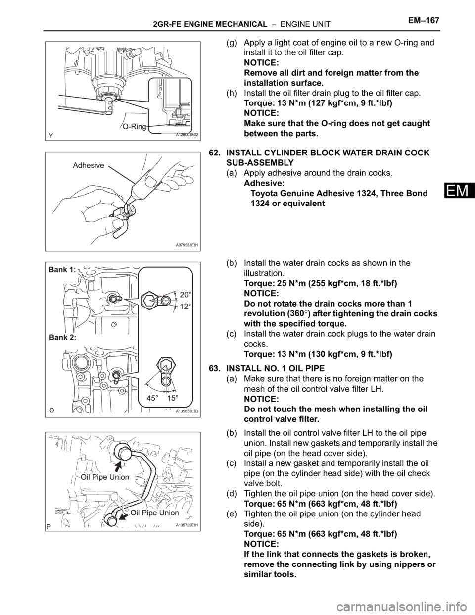
(g) Apply a light coat of engine oil to a new O-ring and
install it to the oil filter cap.
NOTICE:
Remove all dirt and foreign matter from the
installation surface.
(h) Install the oil filter drain plug to the oil filter cap.
Torque: 13 N*m (127 kgf*cm, 9 ft.*lbf)
NOTICE:
Make sure that the O-ring does not get caught
between the parts.
62. INSTALL CYLINDER BLOCK WATER DRAIN COCK
SUB-ASSEMBLY
(a) Apply adhesive around the drain cocks.
Adhesive:
Toyota Genuine Adhesive 1324, Three Bond
1324 or equivalent
(b) Install the water drain cocks as shown in the
illustration.
Torque: 25 N*m (255 kgf*cm, 18 ft.*lbf)
NOTICE:
Do not rotate the drain cocks more than 1
revolution (360
) after tightening the drain cocks
with the specified torque.
(c) Install the water drain cock plugs to the water drain
cocks.
Torque: 13 N*m (130 kgf*cm, 9 ft.*lbf)
63. INSTALL NO. 1 OIL PIPE
(a) Make sure that there is no foreign matter on the
mesh of the oil control valve filter LH.
NOTICE:
Do not touch the mesh when installing the oil
control valve filter.
(b) Install the oil control valve filter LH to the oil pipe
union. Install new gaskets and temporarily install the
oil pipe (on the head cover side).
(c) Install a new gasket and temporarily install the oil
pipe (on the cylinder head side) with the oil check
valve bolt.
(d) Tighten the oil pipe union (on the head cover side).
Torque: 65 N*m (663 kgf*cm, 48 ft.*lbf)
(e) Tighten the oil pipe union (on the cylinder head
side).
Torque: 65 N*m (663 kgf*cm, 48 ft.*lbf)
NOTICE:
If the link that connects the gaskets is broken,
remove the connecting link by using nippers or
similar tools.
A128003E02
A076531E01
A135830E03
A135726E01
Page 985 of 3000

EM–262GR-FE ENGINE MECHANICAL – ENGINE ASSEMBLY
EM
REMOVAL
1. DISCHARGE FUEL SYSTEM PRESSURE (See page
FU-13)
2. DISCHARGE REFRIGERANT FROM
REFRIGERATION SYSTEM (See page AC-172)
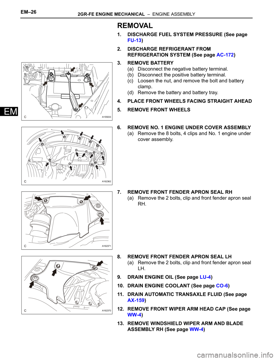
3. REMOVE BATTERY
(a) Disconnect the negative battery terminal.
(b) Disconnect the positive battery terminal.
(c) Loosen the nut, and remove the bolt and battery
clamp.
(d) Remove the battery and battery tray.
4. PLACE FRONT WHEELS FACING STRAIGHT AHEAD
5. REMOVE FRONT WHEELS
6. REMOVE NO. 1 ENGINE UNDER COVER ASSEMBLY
(a) Remove the 8 bolts, 4 clips and No. 1 engine under
cover assembly.
7. REMOVE FRONT FENDER APRON SEAL RH
(a) Remove the 2 bolts, clip and front fender apron seal
RH.
8. REMOVE FRONT FENDER APRON SEAL LH
(a) Remove the 2 bolts, clip and front fender apron seal
LH.
9. DRAIN ENGINE OIL (See page LU-4)
10. DRAIN ENGINE COOLANT (See page CO-6)
11. DRAIN AUTOMATIC TRANSAXLE FLUID (See page
AX-159)
12. REMOVE FRONT WIPER ARM HEAD CAP (See page
WW-4)
13. REMOVE WINDSHIELD WIPER ARM AND BLADE
ASSEMBLY RH (See page WW-4)
A155033
A162362
A162371
A162370
Page 1023 of 3000
EM–762GR-FE ENGINE MECHANICAL – ENGINE UNIT
EM
DISASSEMBLY
1. REMOVE OIL FILLER CAP SUB-ASSEMBLY
(a) Remove the oil filler cap sub-assembly and oil filler
gasket.
2. REMOVE SPARK PLUG
(a) Remove the spark plugs.
3. REMOVE OIL PAN DRAIN PLUG
(a) Remove the oil pan drain plug and oil pan drain plug
gasket.
4. REMOVE VENTILATION VALVE SUB-ASSEMBLY
(a) Remove the ventilation valve sub-assembly.
5. REMOVE CAMSHAFT POSITION SENSOR
(a) Remove the 4 bolts and 4 camshaft position
sensors.
A129654
A129655
A129656E04
Page 1028 of 3000
2GR-FE ENGINE MECHANICAL – ENGINE UNITEM–81
EM
16. REMOVE WATER INLET HOUSING
(a) Remove the 2 nuts, water inlet and thermostat.
(b) Remove the gasket.
(c) Remove the drain cock plug.
(d) Remove the drain cock assembly.
(e) Remove the 2 stud bolts.
(f) Separate the No. 1 water by-pass hose.
(g) Remove the 2 bolts, nut, and water inlet housing.
(h) Remove the 2 O-rings.
17. REMOVE WATER OUTLET
(a) Remove the 2 bolts, 4 nuts and water outlet.
(b) Remove the 2 gaskets and O-ring.
A129673
A134879E01
A129675
A129676E01
A129677
Page 1105 of 3000
EM–1582GR-FE ENGINE MECHANICAL – ENGINE UNIT
EM
(b) Install the stud bolts.
Torque: 4.0 N*m (41 kgf*cm, 35 in.*lbf)
(c) Install the water inlet housing with the 2 bolts and
nut.
Torque: 10 N*m (102 kgf*cm, 7 ft.*lbf)
NOTICE:
Be careful that the O-ring does not get caught
between the parts.
(d) Connect the No. 1 water by-pass hose.
(e) Apply adhesive around the drain cock.
Adhesive:
Toyota Genuine Adhesive 1324, Three Bond
1324 or equivalent
(f) Install the drain cock assembly to the water inlet
housing.
Torque: 30 N*m (306 kgf*cm, 22 ft.*lbf)
(g) Install the drain cock plug to the water drain cock
assembly.
Torque: 13 N*m (130 kgf*cm, 9 ft.*lbf)
(h) Install a new gasket to the thermostat.
(i) Align the thermostat jiggle valve with the upper stud
bolt, and insert the thermostat in the water inlet
housing.
HINT:
The jiggle valve may be set within 10
of either side
of the prescribed positions.
A137975E01
A134879E01
A134896E01
Page 1109 of 3000
EM–1622GR-FE ENGINE MECHANICAL – ENGINE UNIT
EM
53. INSTALL NO. 2 OIL PAN SUB-ASSEMBLY
(a) Using an E6 "TORX" socket, install the stud bolts as
shown in the illustration.
Torque: 4.0 N*m (41 kgf*cm, 35 in.*lbf)
(b) Apply seal packing in a continuous line as shown in
the illustration.
Seal packing:
Toyota Genuine Seal Packing Black, Three
Bond 1207B or equivalent
Seal diameter:
3.0 to 4.0 mm (0.118 to 0.158 in.)
NOTICE:
• Remove any oil from the contact surface.
• Install the oil pan No. 2 within 3 minutes after
applying seal packing.
• Do not start the engine for at least 2 hours
after installing.
(c) Install the oil pan with the 16 bolts and 2 nuts.
Torque: 10 N*m (102 kgf*cm, 7 ft.*lbf)
54. INSTALL OIL PAN DRAIN PLUG
(a) Install a new oil pan drain plug gasket and the oil
pan drain plug.
Torque: 40 N*m (408 kgf*cm, 30 ft.*lbf)
A134964E01
A132234E02
A129680E01
A129654
Page 1114 of 3000

2GR-FE ENGINE MECHANICAL – ENGINE UNITEM–167
EM
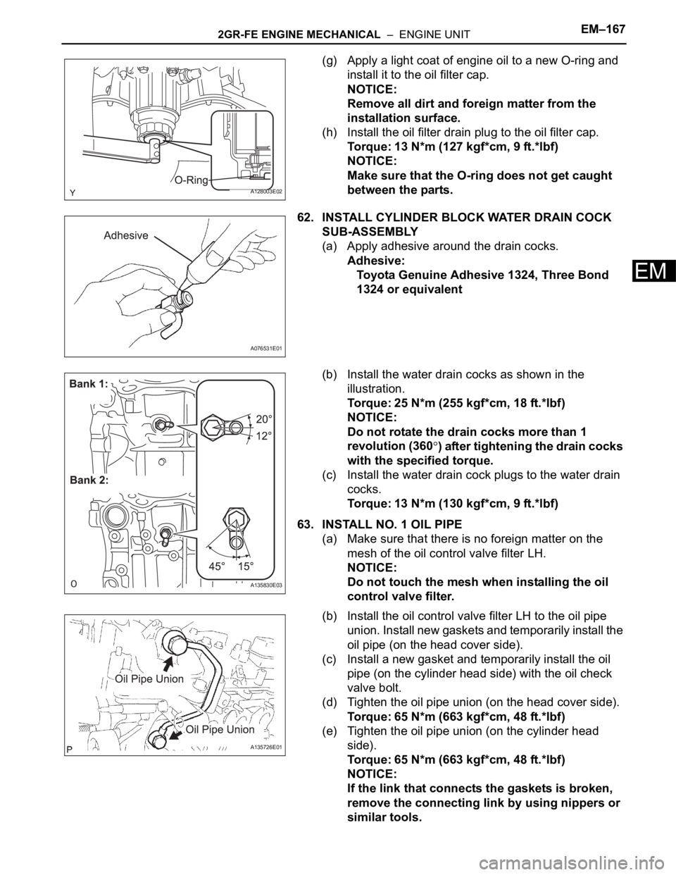
(g) Apply a light coat of engine oil to a new O-ring and
install it to the oil filter cap.
NOTICE:
Remove all dirt and foreign matter from the
installation surface.
(h) Install the oil filter drain plug to the oil filter cap.
Torque: 13 N*m (127 kgf*cm, 9 ft.*lbf)
NOTICE:
Make sure that the O-ring does not get caught
between the parts.
62. INSTALL CYLINDER BLOCK WATER DRAIN COCK
SUB-ASSEMBLY
(a) Apply adhesive around the drain cocks.
Adhesive:
Toyota Genuine Adhesive 1324, Three Bond
1324 or equivalent
(b) Install the water drain cocks as shown in the
illustration.
Torque: 25 N*m (255 kgf*cm, 18 ft.*lbf)
NOTICE:
Do not rotate the drain cocks more than 1
revolution (360
) after tightening the drain cocks
with the specified torque.
(c) Install the water drain cock plugs to the water drain
cocks.
Torque: 13 N*m (130 kgf*cm, 9 ft.*lbf)
63. INSTALL NO. 1 OIL PIPE
(a) Make sure that there is no foreign matter on the
mesh of the oil control valve filter LH.
NOTICE:
Do not touch the mesh when installing the oil
control valve filter.
(b) Install the oil control valve filter LH to the oil pipe
union. Install new gaskets and temporarily install the
oil pipe (on the head cover side).
(c) Install a new gasket and temporarily install the oil
pipe (on the cylinder head side) with the oil check
valve bolt.
(d) Tighten the oil pipe union (on the head cover side).
Torque: 65 N*m (663 kgf*cm, 48 ft.*lbf)
(e) Tighten the oil pipe union (on the cylinder head
side).
Torque: 65 N*m (663 kgf*cm, 48 ft.*lbf)
NOTICE:
If the link that connects the gaskets is broken,
remove the connecting link by using nippers or
similar tools.
A128003E02
A076531E01
A135830E03
A135726E01