Page 1822 of 3000

AX–136U151F AUTOMATIC TRANSAXLE – VALVE BODY ASSEMBLY
AX
REMOVAL
1. REMOVE ENGINE UNDER COVER NO.1
2. DISCONNECT CABLE FROM NEGATIVE BATTERY
TERMINAL
3. DRAIN AUTOMATIC TRANSAXLE FLUID (See page
AX-131)
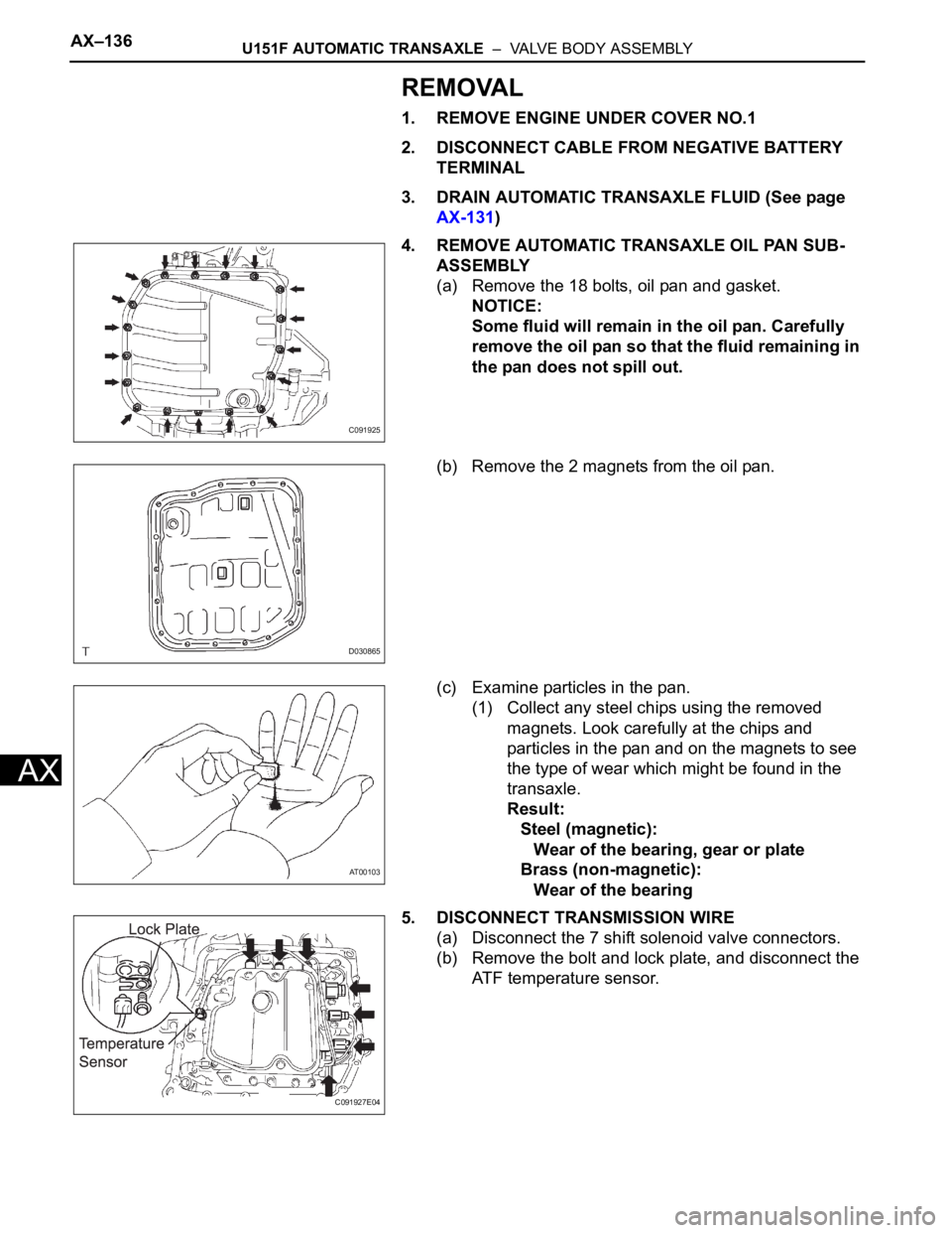
4. REMOVE AUTOMATIC TRANSAXLE OIL PAN SUB-
ASSEMBLY
(a) Remove the 18 bolts, oil pan and gasket.
NOTICE:
Some fluid will remain in the oil pan. Carefully
remove the oil pan so that the fluid remaining in
the pan does not spill out.
(b) Remove the 2 magnets from the oil pan.
(c) Examine particles in the pan.
(1) Collect any steel chips using the removed
magnets. Look carefully at the chips and
particles in the pan and on the magnets to see
the type of wear which might be found in the
transaxle.
Result:
Steel (magnetic):
Wear of the bearing, gear or plate
Brass (non-magnetic):
Wear of the bearing
5. DISCONNECT TRANSMISSION WIRE
(a) Disconnect the 7 shift solenoid valve connectors.
(b) Remove the bolt and lock plate, and disconnect the
ATF temperature sensor.
C091925
D030865
AT00103
C091927E04
Page 2031 of 3000
TF–8TRANSFER – TRANSFER ASSEMBLY
TF
REMOVAL
1. REMOVE ENGINE AND TRANSAXLE
HINT:
(See page EM-26)
2. REMOVE AUTOMATIC TRANSMISSION WITH
TRANSFER
HINT:
(See page AX-164)
3. REMOVE NO. 1 TRANSFER CASE PLUG
(a) Remove the No. 1 transfer case plug.
(b) Remove the No. 1 gasket from the transfer case No.
1 plug.
4. REMOVE NO. 2 TRANSFER CASE PLUG
(a) Remove the No. 2 transfer case plug.
(b) Remove the No. 2 gasket from the No. 2 transfer
case plug.
5. REMOVE TRANSFER DRAIN PLUG
(a) Remove the transfer drain plug and bleed the oil.
(b) Remove the drain gasket from the transfer drain
plug.
6. REMOVE TRANSFER ASSEMBLY
(a) Remove the 2 bolts and 6 bolts.
(b) Using a plastic hammer, remove the transfer
assembly from the transaxle assembly.
NOTICE:
• Remove the transfer assembly from the
transaxle assembly without tilting it.
• When removing the transfer assembly, do not
hold onto the oil seal parts on both sides of
the assembly.
C082977E01
C082785E01
Page 2032 of 3000

TRANSFER – TRANSFER ASSEMBLYTF–9
TF
INSTALLATION
1. INSTALL TRANSFER ASSEMBLY
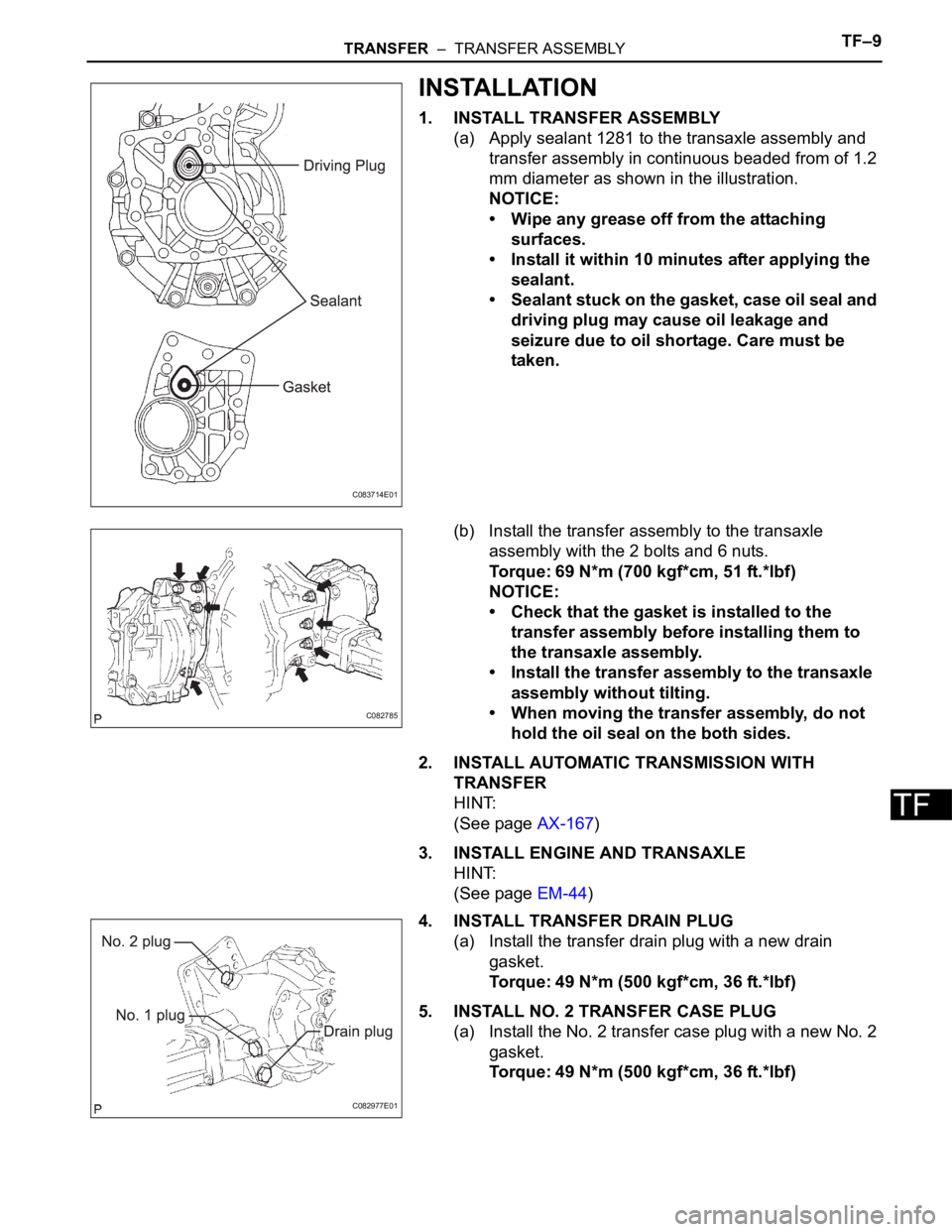
(a) Apply sealant 1281 to the transaxle assembly and
transfer assembly in continuous beaded from of 1.2
mm diameter as shown in the illustration.
NOTICE:
• Wipe any grease off from the attaching
surfaces.
• Install it within 10 minutes after applying the
sealant.
• Sealant stuck on the gasket, case oil seal and
driving plug may cause oil leakage and
seizure due to oil shortage. Care must be
taken.
(b) Install the transfer assembly to the transaxle
assembly with the 2 bolts and 6 nuts.
Torque: 69 N*m (700 kgf*cm, 51 ft.*lbf)
NOTICE:
• Check that the gasket is installed to the
transfer assembly before installing them to
the transaxle assembly.
• Install the transfer assembly to the transaxle
assembly without tilting.
• When moving the transfer assembly, do not
hold the oil seal on the both sides.
2. INSTALL AUTOMATIC TRANSMISSION WITH
TRANSFER
HINT:
(See page AX-167)
3. INSTALL ENGINE AND TRANSAXLE
HINT:
(See page EM-44)
4. INSTALL TRANSFER DRAIN PLUG
(a) Install the transfer drain plug with a new drain
gasket.
Torque: 49 N*m (500 kgf*cm, 36 ft.*lbf)
5. INSTALL NO. 2 TRANSFER CASE PLUG
(a) Install the No. 2 transfer case plug with a new No. 2
gasket.
Torque: 49 N*m (500 kgf*cm, 36 ft.*lbf)
C083714E01
C082785
C082977E01
Page 2080 of 3000

DRIVE SHAFT – FRONT DRIVE SHAFTDS–5
DS
REMOVAL
1. DRAIN AUTOMATIC TRANSAXLE FLUID
(a) Remove the drain plug, gasket and drain ATF.
(b) Install a new gasket and the drain plug.
Torque: 49 N*m (500 kgf*cm, 36 ft.*lbf)
2. DRAIN TRANSFER OIL (for 4WD)
HINT:
(See page TF-8)
3. REMOVE FRONT WHEEL
4. REMOVE FRONT AXLE HUB LH NUT
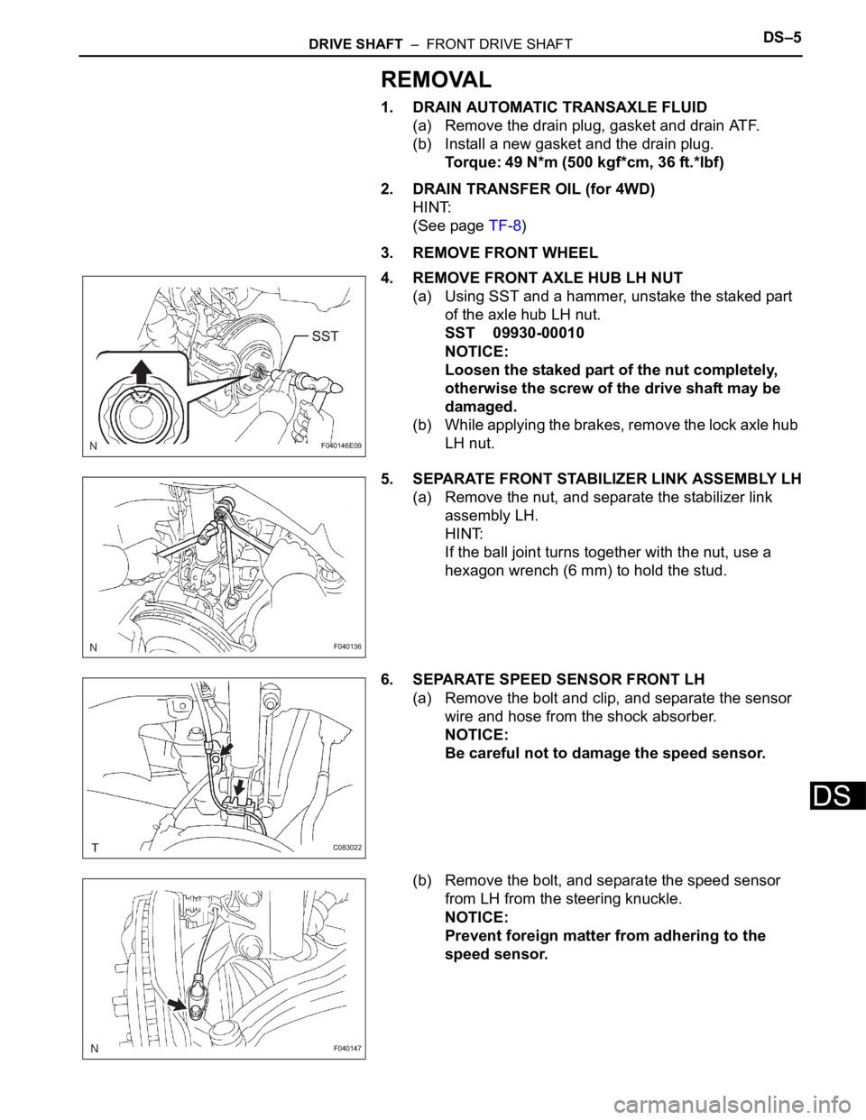
(a) Using SST and a hammer, unstake the staked part
of the axle hub LH nut.
SST 09930-00010
NOTICE:
Loosen the staked part of the nut completely,
otherwise the screw of the drive shaft may be
damaged.
(b) While applying the brakes, remove the lock axle hub
LH nut.
5. SEPARATE FRONT STABILIZER LINK ASSEMBLY LH
(a) Remove the nut, and separate the stabilizer link
assembly LH.
HINT:
If the ball joint turns together with the nut, use a
hexagon wrench (6 mm) to hold the stud.
6. SEPARATE SPEED SENSOR FRONT LH
(a) Remove the bolt and clip, and separate the sensor
wire and hose from the shock absorber.
NOTICE:
Be careful not to damage the speed sensor.
(b) Remove the bolt, and separate the speed sensor
from LH from the steering knuckle.
NOTICE:
Prevent foreign matter from adhering to the
speed sensor.
F040146E09
F040136
C083022
F040147
Page 2110 of 3000

DF–10DIFFERENTIAL – REAR DIFFERENTIAL CARRIER ASSEMBLY
DF
REMOVAL
1. REMOVE REAR WHEEL
2. REMOVE EXHAUST PIPE ASSEMBLY
HINT:
(See page EX-8)
3. REMOVE PROPELLER WITH CENTER BEARING
SHAFT ASSEMBLY
HINT:
(See page PR-3)
4. REMOVE REAR DIFFERENTIAL FILLER PLUG
(a) Using a hexagon wrench (10 mm), remove the filler
plug and gasket.
5. REMOVE REAR DIFFERENTIAL DRAIN PLUG
(a) Using a hexagon wrench (10 mm), remove the drain
plug and gasket, and drain the oil.
6. REMOVE REAR SPEED SENSOR LH
HINT:
Removal procedure or RH side is the same as that or LH
side. (See page DS-21)
7. REMOVE REAR AXLE SHAFT NUT LH
HINT:
Removal procedure or RH side is the same as that or LH
side. (See page DS-21)
8. REMOVE REAR DRIVE SHAFT ASSEMBLY LH
HINT:
Removal procedure or RH side is the same as that or LH
side. (See page DS-21)
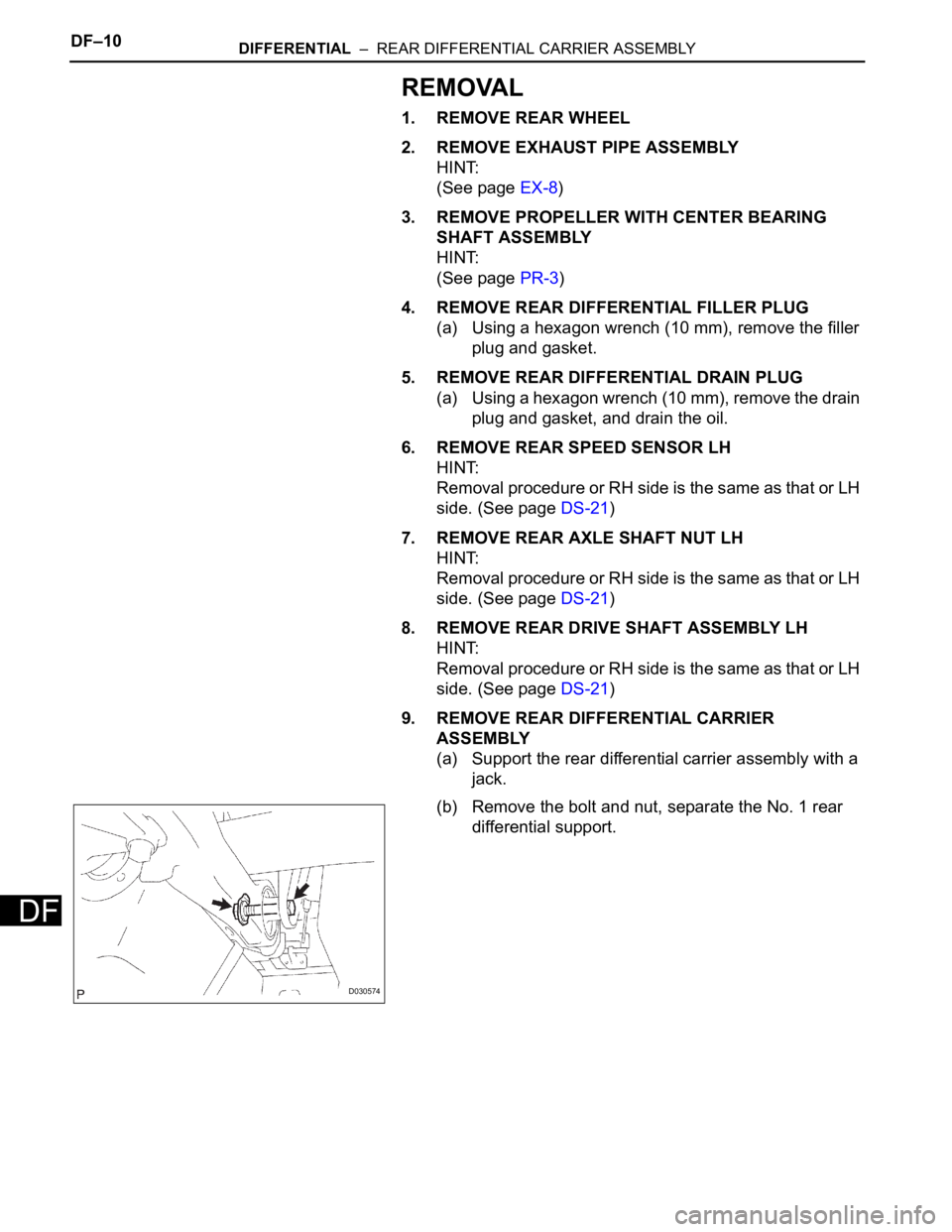
9. REMOVE REAR DIFFERENTIAL CARRIER
ASSEMBLY
(a) Support the rear differential carrier assembly with a
jack.
(b) Remove the bolt and nut, separate the No. 1 rear
differential support.
D030574
Page 2225 of 3000
SP–42SUSPENSION – REAR COIL SPRING
SP
10. SEPARATE PARKING BRAKE CABLE ASSEMBLY
NO.3
(a) Remove the 2 bolts and parking brake cable
assembly No.3.
11. SEPARATE PARKING BRAKE CABLE ASSEMBLY
NO.2
HINT:
Separate the RH side by the same procedures as the LH
side.
12. SEPARATE REAR BRAKE TUBE NO.2
(a) Using SST, separate the brake tube from the flexible
hose. Catch the brake fluid with a container as it
drains out.
SST 09023-00101
(b) Remove the clip, and separate the flexible hose.
(c) Remove the bolt and separate the brake tube from
rear axle beam assembly.
13. SEPARATE REAR BRAKE TUBE NO.1
SST 09023-00101
HINT:
Separate the RH side by the same procedures as the LH
side.
14. REMOVE FUEL TANK FILLER HOSE COVER
(a) Remove the 2 bolts, 3 screws, 3 nuts and fuel tank
filler pipe protector.
G023904
G025779E01
G025780
C088688
Page 2546 of 3000
BC–180BRAKE CONTROL – BRAKE ACTUATOR (w/ VSC)
BC
REMOVAL
1. DRAIN BRAKE FLUID
NOTICE:
Wash brake fluid off immediately if it adheres to any
painted surface.
2. DISCONNECT BATTERY NEGATIVE TERMINAL
3. REMOVE AIR CLEANER ASSEMBLY WITH HOSE
4. REMOVE BRAKE ACTUATOR WITH BRACKET
(a) Release the latch of the brake actuator connector to
disconnect the connector.
(b) Using SST, disconnect the 6 brake tubes from the
actuator with bracket.
SST 09023-00101
(c) Use tags or make a memo to identify the places to
reconnect.
(d) Remove the 3 bolts and the actuator with bracket.
NOTICE:
Be careful not to damage the brake tubes and
wire harness.
5. REMOVE BRAKE ACTUATOR
(a) Remove the 2 nuts and the brake actuator assembly
from the brake actuator bracket.
G024309
F045511E01
G024308
Page 2557 of 3000
BRAKE CONTROL – BRAKE ACTUATOR (w/o VSC)BC–185
BC
REMOVAL
1. DRAIN BRAKE FLUID
NOTICE:
Wash brake fluid off immediately if it adheres to any
painted surface.
2. DISCONNECT BATTERY NEGATIVE TERMINAL
3. REMOVE AIR CLEANER ASSEMBLY WITH HOSE
4. REMOVE BRAKE ACTUATOR WITH BRACKET
(a) Release the latch of the brake actuator connector to
disconnect the connector
(b) Using SST, disconnect the 6 brake tubes from the
actuator with bracket.
SST 09023-00101
(c) Use tags or make a memo to identify the places to
reconnect.
(d) Remove the 3 bolts and the actuator with bracket.
NOTICE:
Be careful not to damage the brake tubes and
wire harness.
5. REMOVE BRAKE ACTUATOR
(a) Remove the 2 nuts and the brake actuator assembly
from the brake actuator bracket.
G024306
F045470E01
G024307