Page 2593 of 3000

BR–20BRAKE – BRAKE BOOSTER
BR
REMOVAL
NOTICE:
• Do not adjust the brake booster push rod.
• Do not change the combination of the diameter
converting unit and brake.
1. REMOVE FRONT WHEEL
2. DRAIN BRAKE FLUID
NOTICE:
Wash the brake fluid off immediately if it attaches to
any painted surfaces.
3. SEPARATE BATTERY NEGATIVE TERMINAL
4. REMOVE FRONT DOOR SCUFF PLATE LH
5. REMOVE COWL SIDE TRIM BOARD LH
(a) Remove the nut and cowl trim board plate LH.
6. REMOVE INSTRUMENT PANEL FINISH PANEL SUB-
ASSEMBLY LOWER LH
(a) Remove the 2 bolts and instrument panel finish
panel sub-assembly lower LH.
7. REMOVE INSTRUMENT PANEL SAFETY PAD
INSERT SUB-ASSEMBLY NO. 1
(a) Remove the 4 bolts and instrument panel safety pad
insert sub-assembly No. 1.
8. REMOVE COWL TOP PANEL SUB-ASSEMBLY
OUTER FRONT (See page SP-13)
9. REMOVE AIR CLEANER ASSEMBLY WITH HOSE
10. REMOVE BRAKE ACTUATOR ASSEMBLY (w/o VSC)
SST 09023-00101
HINT:
See page BC-184.
11. REMOVE ABS & TRACTION ACTUATOR ASSEMBLY
(w/ VSC)
SST 09023-00101
HINT:
See page BC-179.
12. REMOVE BRAKE LINE
(a) Remove the front brake tube No. 1, front brake tube
No. 2, front brake tube No. 3 and front brake tube
No. 4.
(b) Remove the rear brake tube No. 1 and rear brake
tube No. 2.
13. REMOVE PUSH ROD PIN
(a) Remove the push rod pin from the brake booster
push rod.
14. REMOVE BRAKE MASTER CYLINDER ASSEMBLY
(a) Slide the clip and disconnect the brake master
cylinder reservoir hose from the brake master
cylinder union.
Page 2619 of 3000

BR–24BRAKE – FRONT BRAKE
BR
REMOVAL
HINT:
Remove the RH side by the same procedure as the LH side.
1. REMOVE FRONT WHEEL
2. DRAIN BRAKE FLUID
NOTICE:
Wash the brake fluid off immediately if it attaches to
any painted surface.
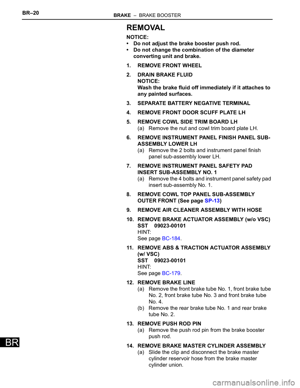
3. REMOVE FRONT DISC BRAKE CYLINDER SUB-
ASSEMBLY
(a) Remove the union bolt and 2 gaskets from the front
disc brake cylinder sub-assembly, then disconnect
the flexible hose.
(b) Hold the front disc brake cylinder slide pin and
remove the 2 bolts.
4. REMOVE DISC BRAKE PAD KIT FRONT (PAD ONLY)
(a) Remove the disc brake pad kit front from the front
disc brake cylinder mounting LH.
5. REMOVE ANTI SQUEAL SHIM KIT FRONT
(a) Remove the anti squeal shim and pad wear
indicator plate from the each pad.
6. REMOVE FRONT DISC BRAKE PAD SUPPORT
PLATE
(a) Remove the front disc brake pad support plate (No.
1) and front disc brake pad support plate (No. 2)
from the front disc brake cylinder mounting LH.
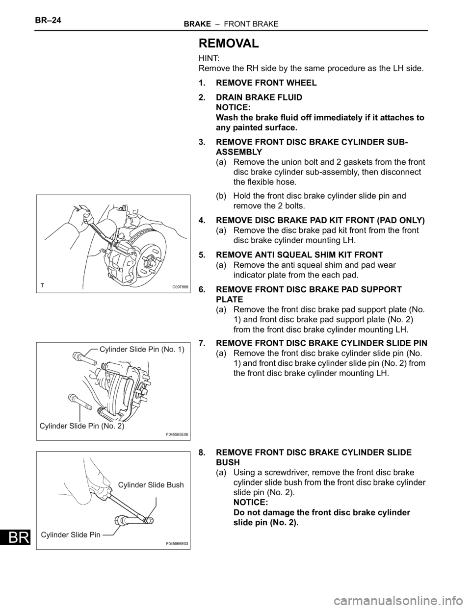
7. REMOVE FRONT DISC BRAKE CYLINDER SLIDE PIN
(a) Remove the front disc brake cylinder slide pin (No.
1) and front disc brake cylinder slide pin (No. 2) from
the front disc brake cylinder mounting LH.
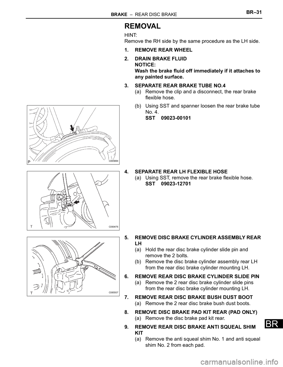
8. REMOVE FRONT DISC BRAKE CYLINDER SLIDE
BUSH
(a) Using a screwdriver, remove the front disc brake
cylinder slide bush from the front disc brake cylinder
slide pin (No. 2).
NOTICE:
Do not damage the front disc brake cylinder
slide pin (No. 2).
C097868
F045565E06
F045566E03
Page 2628 of 3000

BRAKE – REAR DISC BRAKEBR–31
BR
REMOVAL
HINT:
Remove the RH side by the same procedure as the LH side.
1. REMOVE REAR WHEEL
2. DRAIN BRAKE FLUID
NOTICE:
Wash the brake fluid off immediately if it attaches to
any painted surface.
3. SEPARATE REAR BRAKE TUBE NO.4
(a) Remove the clip and a disconnect, the rear brake
flexible hose.
(b) Using SST and spanner loosen the rear brake tube
No. 4.
SST 09023-00101
4. SEPARATE REAR LH FLEXIBLE HOSE
(a) Using SST, remove the rear brake flexible hose.
SST 09023-12701
5. REMOVE DISC BRAKE CYLINDER ASSEMBLY REAR
LH
(a) Hold the rear disc brake cylinder slide pin and
remove the 2 bolts.
(b) Remove the disc brake cylinder assembly rear LH
from the rear disc brake cylinder mounting LH.
6. REMOVE REAR DISC BRAKE CYLINDER SLIDE PIN
(a) Remove the 2 rear disc brake cylinder slide pins
from the rear disc brake cylinder mounting LH.
7. REMOVE REAR DISC BRAKE BUSH DUST BOOT
(a) Remove the 2 rear disc brake bush dust boots.
8. REMOVE DISC BRAKE PAD KIT REAR (PAD ONLY)
(a) Remove the disc brake pad kit rear.
9. REMOVE REAR DISC BRAKE ANTI SQUEAL SHIM
KIT
(a) Remove the anti squeal shim No. 1 and anti squeal
shim No. 2 from each pad.
C065884
C090476
C085507
Page 2720 of 3000
POWER STEERING – VANE PUMPPS–9
PS
REMOVAL
1. DRAIN POWER STEERING FLUID
2. REMOVE FRONT WHEEL RH
3. REMOVE FRONT FENDER APRON SEAL RH (See
page EM-26)
4. REMOVE FAN AND GENERATOR V BELT (See page
EM-6)
5. DISCONNECT NO. 1 FLUID RESERVOIR TO PUMP
HOSE
(a) Slide the clip and disconnect the No. 1 fluid
reservoir to pump hose from the vane pump
assembly.
6. DISCONNECT PRESSURE FEED TUBE ASSEMBLY
(a) Remove the union bolt and disconnect the pressure
feed tube assembly from the vane pump assembly.
(b) Remove the gasket from the pressure feed tube
assembly.
7. DISCONNECT POWER STEERING FLUID PRESSURE
SWITCH CONNECTOR
(a) Disconnect the power steering fluid pressure switch
connector.
C133174E02
C161546
C161547