2007 TOYOTA SIENNA catalytic converter
[x] Cancel search: catalytic converterPage 474 of 3000

ES–1682GR-FE ENGINE CONTROL SYSTEM – SFI SYSTEM
ES
HINT:
Sensor 2 refers to the sensor mounted behind the Three-Way Catalytic Converter (TWC) and located far
from the engine assembly.
DESCRIPTION
A three-way catalytic converter (TWC) is used in order to convert the carbon monoxide (CO), hydro
carbon (HC), and nitrogen oxides (HOx) into less harmful substances. To allow the TWC to function
effectively, it is necessary to keep the air-fuel ratio of the engine near the stoichiometric air-fuel ratio. For
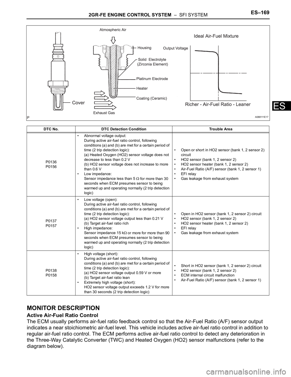
helping the ECM to deliver accurate air-fuel ratio control, a Heated Oxygen (HO2) sensor becomes used.
The HO2 sensor is located behind the TWC, and detects the oxygen concentration in the exhaust gas.
Since the sensor is integrated with the heater that heats the sensing portion, it is possible to detect the
oxygen concentration even when the intake air volume is low (the exhaust gas temperature is low).
When the air-fuel ratio becomes lean, the oxygen concentration in the exhaust gas becomes rich. The
HO2 sensor informs the ECM that the post-TWC air-fuel ratio is lean (low voltage, i.e. less than 0.45 V).
Conversely, when the air-fuel ratio is richer than the stoichiometric air-fuel level, the oxygen concentration
in the exhaust gas becomes lean. The HO2 sensor informs the ECM that the post-TWC air-fuel ratio is
rich (high voltage, i.e. more than 0.45 V). The HO2 sensor has the property of changing its output voltage
drastically when the air-fuel ratio is close to the stoichiometric level.
The ECM uses the supplementary information from the HO2 sensor to determine whether the air-fuel ratio
after the TWC is rich or lean, and adjusts the fuel injection time accordingly. Thus, if the HO2 sensor is
working improperly due to internal malfunctions, the ECM is unable to compensate for deviations in the
primary air-fuel ratio control.
DTC P0136Oxygen Sensor Circuit Malfunction (Bank 1
Sensor 2)
DTC P0137Oxygen Sensor Circuit Low Voltage (Bank 1
Sensor 2)
DTC P0138Oxygen Sensor Circuit High Voltage (Bank 1
Sensor 2)
DTC P0156Oxygen Sensor Circuit Malfunction (Bank 2
Sensor 2)
DTC P0157Oxygen Sensor Circuit Low Voltage (Bank 2
Sensor 2)
DTC P0158Oxygen Sensor Circuit High Voltage (Bank 2
Sensor 2)
Page 475 of 3000
2GR-FE ENGINE CONTROL SYSTEM – SFI SYSTEMES–169
ES
MONITOR DESCRIPTION
Active Air-Fuel Ratio Control
The ECM usually performs air-fuel ratio feedback control so that the Air-Fuel Ratio (A/F) sensor output
indicates a near stoichiometric air-fuel level. This vehicle includes active air-fuel ratio control in addition to
regular air-fuel ratio control. The ECM performs active air-fuel ratio control to detect any deterioration in
the Three-Way Catalytic Converter (TWC) and Heated Oxygen (HO2) sensor malfunctions (refer to the
diagram below).
DTC No. DTC Detection Condition Trouble Area
P0136
P0156• Abnormal voltage output:
During active air-fuel ratio control, following
conditions (a) and (b) are met for a certain period of
time (2 trip detection logic):
(a) Heated Oxygen (HO2) sensor voltage does not
decrease to less than 0.2 V
(b) HO2 sensor voltage does not increase to more
than 0.6 V
• Low impedance:
Sensor impedance less than 5
for more than 30
seconds when ECM presumes sensor to being
warmed up and operating normally (2 trip detection
logic)• Open or short in HO2 sensor (bank 1, 2 sensor 2)
circuit
• HO2 sensor (bank 1, 2 sensor 2)
• HO2 sensor heater (bank 1, 2 sensor 2)
• Air-Fuel Ratio (A/F) sensor (bank 1, 2 sensor 1)
• EFI relay
• Gas leakage from exhaust system
P0137
P0157• Low voltage (open):
During active air-fuel ratio control, following
conditions (a) and (b) are met for a certain period of
time (2 trip detection logic):
(a) HO2 sensor voltage output less than 0.21 V
(b) Target air-fuel ratio rich
• High impedance:
Sensor impedance 15 k
or more for more than 90
seconds when ECM presumes sensor to being
warmed up and operating normally (2 trip detection
logic)• Open in HO2 sensor (bank 1, 2 sensor 2) circuit
• HO2 sensor (bank 1, 2 sensor 2)
• HO2 sensor heater (bank 1, 2 sensor 2)
• EFI relay
• Gas leakage from exhaust system
P0138
P0158• High voltage (short):
During active air-fuel ratio control, following
conditions (a) and (b) are met for a certain period of
time (2 trip detection logic):
(a) HO2 sensor voltage output 0.59 V or more
(b) Target air-fuel ratio lean
• Extremely high voltage (short):
HO2 sensor voltage output exceeds 1.2 V for more
than 30 seconds (2 trip detection logic)• Short in HO2 sensor (bank 1, 2 sensor 2) circuit
• HO2 sensor (bank 1, 2 sensor 2)
• ECM internal circuit malfunction
• Air-Fuel Ratio (A/F) sensor (bank 1, 2 sensor 1)
A 0 8 8 111 E 1 7
Page 476 of 3000
ES–1702GR-FE ENGINE CONTROL SYSTEM – SFI SYSTEM
ES
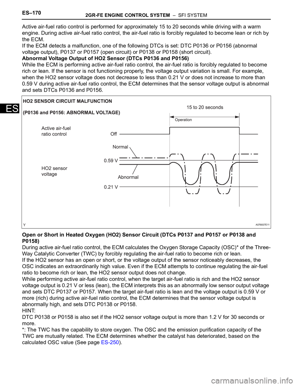
Active air-fuel ratio control is performed for approximately 15 to 20 seconds while driving with a warm
engine. During active air-fuel ratio control, the air-fuel ratio is forcibly regulated to become lean or rich by
the ECM.
If the ECM detects a malfunction, one of the following DTCs is set: DTC P0136 or P0156 (abnormal
voltage output), P0137 or P0157 (open circuit) or P0138 or P0158 (short circuit).
Abnormal Voltage Output of HO2 Sensor (DTCs P0136 and P0156)
While the ECM is performing active air-fuel ratio control, the air-fuel ratio is forcibly regulated to become
rich or lean. If the sensor is not functioning properly, the voltage output variation is small. For example,
when the HO2 sensor voltage does not decrease to less than 0.21 V or does not increase to more than
0.59 V during active air-fuel ratio control, the ECM determines that the sensor voltage output is abnormal
and sets DTCs P0136 and P0156.
Open or Short in Heated Oxygen (HO2) Sensor Circuit (DTCs P0137 and P0157 or P0138 and
P0158)
During active air-fuel ratio control, the ECM calculates the Oxygen Storage Capacity (OSC)* of the Three-
Way Catalytic Converter (TWC) by forcibly regulating the air-fuel ratio to become rich or lean.
If the HO2 sensor has an open or short, or the voltage output of the sensor noticeably decreases, the
OSC indicates an extraordinarily high value. Even if the ECM attempts to continue regulating the air-fuel
ratio to become rich or lean, the HO2 sensor output does not change.
While performing active air-fuel ratio control, when the target air-fuel ratio is rich and the HO2 sensor
voltage output is 0.21 V or less (lean), the ECM interprets this as an abnormally low sensor output voltage
and sets DTC P0137 or P0157. When the target air-fuel ratio is lean and the voltage output is 0.59 V or
more (rich) during active air-fuel ratio control, the ECM determines that the sensor voltage output is
abnormally high, and sets DTC P0138 or P0158.
HINT:
DTC P0138 or P0158 is also set if the HO2 sensor voltage output is more than 1.2 V for 30 seconds or
more.
*: The TWC has the capability to store oxygen. The OSC and the emission purification capacity of the
TWC are mutually related. The ECM determines whether the catalyst has deteriorated, based on the
calculated OSC value (See page ES-250).
A076837E11
Page 510 of 3000
ES–2042GR-FE ENGINE CONTROL SYSTEM – SFI SYSTEM
ES
DESCRIPTION
When the engine misfires, high concentrations of hydrocarbons (HC) enter the exhaust gas. High HC
concentration levels can cause increase in exhaust emission levels. Extremely high concentrations of HC
can also cause increases in the Three-Way Catalytic Converter (TWC) temperature, which may cause
damage to the TWC. To prevent this increase in emissions and to limit the possibility of thermal damage,
the ECM monitors the misfire rate. When the temperature of the TWC reaches the point of thermal
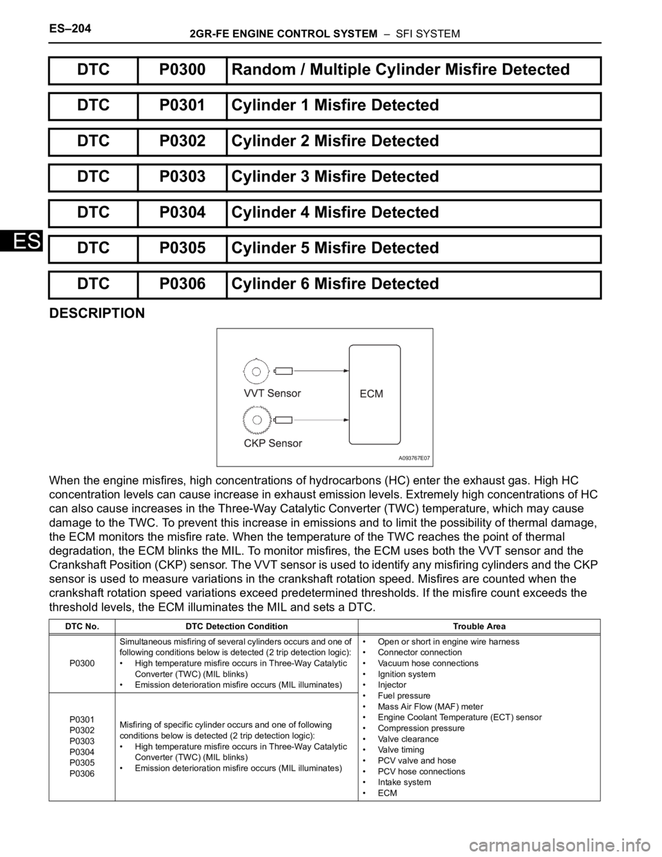
degradation, the ECM blinks the MIL. To monitor misfires, the ECM uses both the VVT sensor and the
Crankshaft Position (CKP) sensor. The VVT sensor is used to identify any misfiring cylinders and the CKP
sensor is used to measure variations in the crankshaft rotation speed. Misfires are counted when the
crankshaft rotation speed variations exceed predetermined thresholds. If the misfire count exceeds the
threshold levels, the ECM illuminates the MIL and sets a DTC.
DTC P0300 Random / Multiple Cylinder Misfire Detected
DTC P0301 Cylinder 1 Misfire Detected
DTC P0302 Cylinder 2 Misfire Detected
DTC P0303 Cylinder 3 Misfire Detected
DTC P0304 Cylinder 4 Misfire Detected
DTC P0305 Cylinder 5 Misfire Detected
DTC P0306 Cylinder 6 Misfire Detected
DTC No. DTC Detection Condition Trouble Area
P0300Simultaneous misfiring of several cylinders occurs and one of
following conditions below is detected (2 trip detection logic):
• High temperature misfire occurs in Three-Way Catalytic
Converter (TWC) (MIL blinks)
• Emission deterioration misfire occurs (MIL illuminates)• Open or short in engine wire harness
• Connector connection
• Vacuum hose connections
• Ignition system
• Injector
• Fuel pressure
• Mass Air Flow (MAF) meter
• Engine Coolant Temperature (ECT) sensor
• Compression pressure
• Valve clearance
• Valve timing
• PCV valve and hose
• PCV hose connections
• Intake system
•ECM P0301
P0302
P0303
P0304
P0305
P0306Misfiring of specific cylinder occurs and one of following
conditions below is detected (2 trip detection logic):
• High temperature misfire occurs in Three-Way Catalytic
Converter (TWC) (MIL blinks)
• Emission deterioration misfire occurs (MIL illuminates)
A093767E07
Page 511 of 3000

2GR-FE ENGINE CONTROL SYSTEM – SFI SYSTEMES–205
ES
When multiple DTCs for misfiring cylinders are set, but DTC P0300 is not set, it indicates that misfires
have been detected in different cylinders at different times. DTC P0300 is only set when several misfiring
cylinders are detected at the same time.
MONITOR DESCRIPTION
The ECM illuminates the MIL and sets a DTC when either one of the following conditions, which could
cause emission deterioration, is detected (2 trip detection logic).
• Within the first 1000 crankshaft revolutions of the engine starting, an excessive misfiring rate
(approximately 20 to 50 misfires per 1000 crankshaft revolutions) occurs once.
• An excessive misfiring rate (approximately 20 to 50 misfires per 1,000 crankshaft revolutions) occurs a
total of 4 times.
The ECM flashes the MIL and sets a DTC when either one of the following conditions, which could cause
the Three-Way Catalytic Converter (TWC) damage, is detected (2 trip detection logic).
• At a high engine rpm, a catalyst damage misfire, which monitored every 200 crankshaft revolutions,
occurs once.
• At a normal engine rpm, a catalyst damage misfire, which monitored every 200 crankshaft revolutions,
occurs 3 times.
HINT:
If a catalyst damage misfire occurs, the ECM informs the driver by flashing the MIL.
MONITOR STRATEGY
TYPICAL ENABLING CONDITIONS
Misfire:
Monitor period of emission-related-misfire:
Related DTCsP0300: Multiple cylinder misfire
P0301: Cylinder 1 misfire
P0302: Cylinder 2 misfire
P0303: Cylinder 3 misfire
P0304: Cylinder 4 misfire
P0305: Cylinder 5 misfire
P0306: Cylinder 6 misfire
Required Sensors / Components (Main) Injector, Ignition coil, Spark plug
Required Sensors / Components (Related)Crankshaft, Camshaft, Engine coolant temperature and intake air temperature
sensors and Mass air flow meter
Frequency of Operation Continuous
Duration1000 to 4000 crankshaft revolutions: Emission related misfire
200 to 600 crankshaft revolutions: Catalyst damaged misfire
MIL Operation2 driving cycles: Emission related misfire
MIL flashes immediately: Catalyst damaged misfire
Sequence of Operation None
The monitor will run whenever these DTCs are not
presentP0100, P0101, P0102, P0103 (MAF Sensor), P0110, P0112, P0113 (IAT Sensor),
P0115, P0116, P0117, P0118 (ECT Sensor), P0120, P0121, P0122, P0123, P0220,
P0222, P0223, P2135 (TP Sensor), P0125 (Insufficient ECT for Closed Loop),
P0327, P0328, P0332, P0333 (Knock Sensor), P0335 (CKP Sensor), P0340, (CMP
Sensor), P0500 (VSS)
Battery voltage 8 V or more
VVT system No operate by scan tool
Engine RPM 450 to 6500 rpm
Either of the following conditions is met Condition (a) or (b)
(a) Engine start ECT More than -7
C (19F)
(b) ECT More than 20
C (68F)
Fuel-cut OFF
First 1000 revolutions after engine start, or check mode Crankshaft 1000 revolutions
Page 656 of 3000
2GR-FE ENGINE CONTROL SYSTEM – SFI SYSTEMES–363
ES
HINT:
• Although the DTC titles say oxygen sensor, these DTCs relate to the Air-Fuel Ratio (A/F) sensor.
• Sensor 1 refers to the sensor mounted in front of the Three-Way Catalytic Converter (TWC) and
located near the engine assembly.
DESCRIPTION
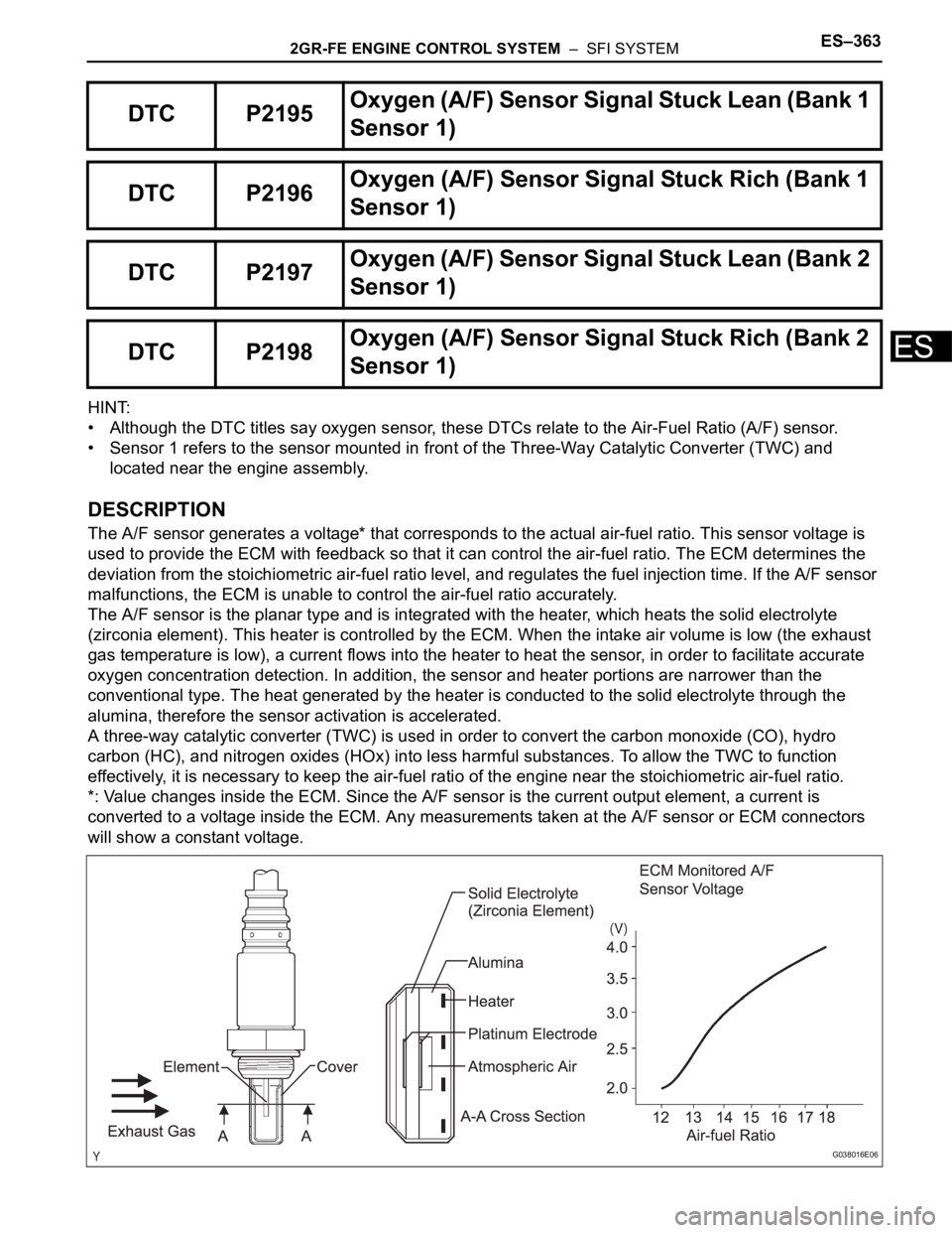
The A/F sensor generates a voltage* that corresponds to the actual air-fuel ratio. This sensor voltage is
used to provide the ECM with feedback so that it can control the air-fuel ratio. The ECM determines the
deviation from the stoichiometric air-fuel ratio level, and regulates the fuel injection time. If the A/F sensor
malfunctions, the ECM is unable to control the air-fuel ratio accurately.
The A/F sensor is the planar type and is integrated with the heater, which heats the solid electrolyte
(zirconia element). This heater is controlled by the ECM. When the intake air volume is low (the exhaust
gas temperature is low), a current flows into the heater to heat the sensor, in order to facilitate accurate
oxygen concentration detection. In addition, the sensor and heater portions are narrower than the
conventional type. The heat generated by the heater is conducted to the solid electrolyte through the
alumina, therefore the sensor activation is accelerated.
A three-way catalytic converter (TWC) is used in order to convert the carbon monoxide (CO), hydro
carbon (HC), and nitrogen oxides (HOx) into less harmful substances. To allow the TWC to function
effectively, it is necessary to keep the air-fuel ratio of the engine near the stoichiometric air-fuel ratio.
*: Value changes inside the ECM. Since the A/F sensor is the current output element, a current is
converted to a voltage inside the ECM. Any measurements taken at the A/F sensor or ECM connectors
will show a constant voltage.
DTC P2195Oxyg en ( A/ F) S en so r S ig n al Stu ck Lea n (Ban k 1
Sensor 1)
DTC P2196Oxygen (A/F) Sensor Signal Stuck Rich (Bank 1
Sensor 1)
DTC P2197Oxyg en ( A/ F) S en so r S ig n al Stu ck Lea n (Ban k 2
Sensor 1)
DTC P2198Oxygen (A/F) Sensor Signal Stuck Rich (Bank 2
Sensor 1)
G038016E06
Page 673 of 3000
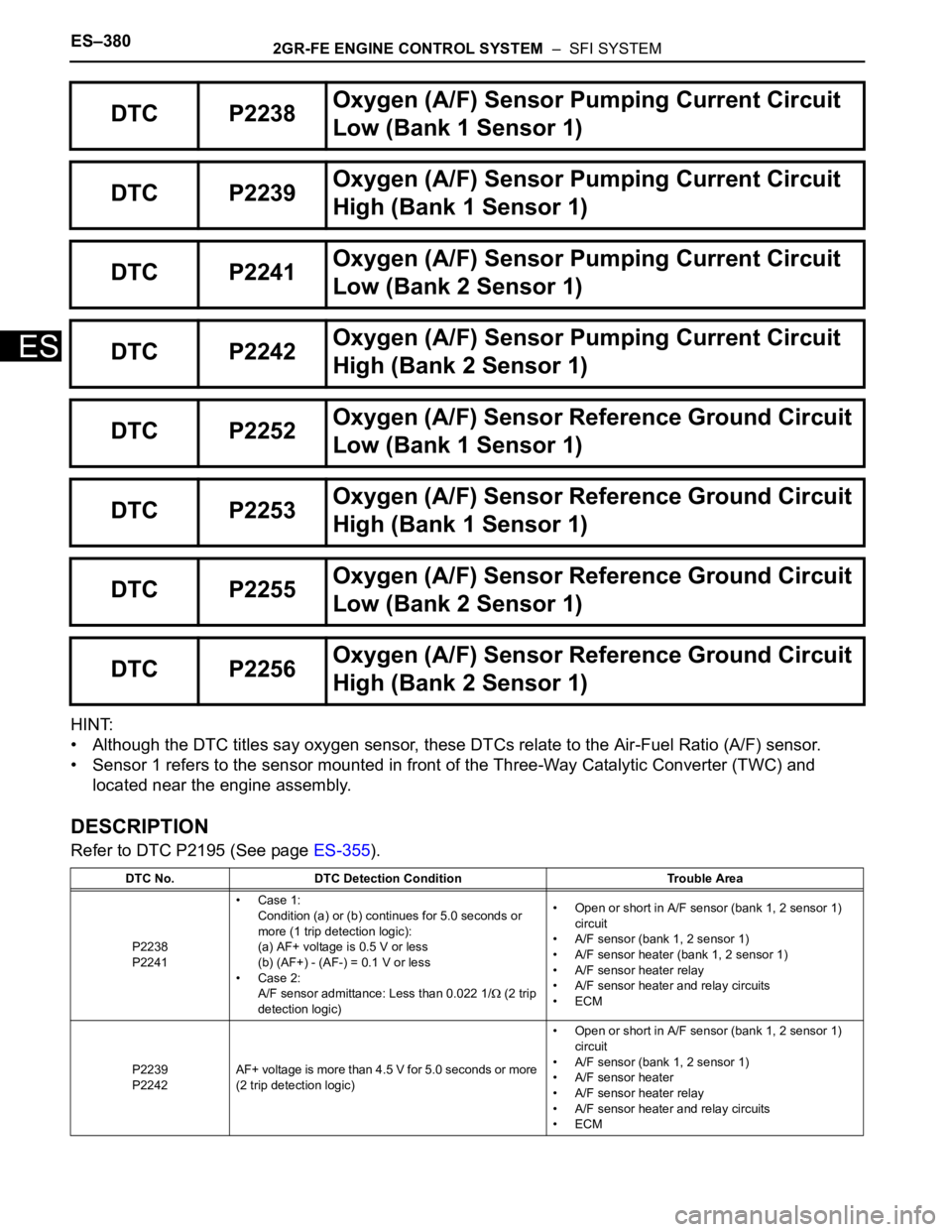
ES–3802GR-FE ENGINE CONTROL SYSTEM – SFI SYSTEM
ES
HINT:
• Although the DTC titles say oxygen sensor, these DTCs relate to the Air-Fuel Ratio (A/F) sensor.
• Sensor 1 refers to the sensor mounted in front of the Three-Way Catalytic Converter (TWC) and
located near the engine assembly.
DESCRIPTION
Refer to DTC P2195 (See page ES-355).
DTC P2238Oxygen (A/F) Sensor Pumping Current Circuit
Low (Bank 1 Sensor 1)
DTC P2239Oxygen (A/F) Sensor Pumping Current Circuit
High (Bank 1 Sensor 1)
DTC P2241Oxygen (A/F) Sensor Pumping Current Circuit
Low (Bank 2 Sensor 1)
DTC P2242Oxygen (A/F) Sensor Pumping Current Circuit
High (Bank 2 Sensor 1)
DTC P2252Oxygen (A/F) Sensor Reference Ground Circuit
Low (Bank 1 Sensor 1)
DTC P2253Oxygen (A/F) Sensor Reference Ground Circuit
High (Bank 1 Sensor 1)
DTC P2255Oxygen (A/F) Sensor Reference Ground Circuit
Low (Bank 2 Sensor 1)
DTC P2256Oxygen (A/F) Sensor Reference Ground Circuit
High (Bank 2 Sensor 1)
DTC No. DTC Detection Condition Trouble Area
P2238
P2241•Case 1:
Condition (a) or (b) continues for 5.0 seconds or
more (1 trip detection logic):
(a) AF+ voltage is 0.5 V or less
(b) (AF+) - (AF-) = 0.1 V or less
•Case 2:
A/F sensor admittance: Less than 0.022 1/
(2 trip
detection logic)• Open or short in A/F sensor (bank 1, 2 sensor 1)
circuit
• A/F sensor (bank 1, 2 sensor 1)
• A/F sensor heater (bank 1, 2 sensor 1)
• A/F sensor heater relay
• A/F sensor heater and relay circuits
•ECM
P2239
P2242AF+ voltage is more than 4.5 V for 5.0 seconds or more
(2 trip detection logic)• Open or short in A/F sensor (bank 1, 2 sensor 1)
circuit
• A/F sensor (bank 1, 2 sensor 1)
• A/F sensor heater
• A/F sensor heater relay
• A/F sensor heater and relay circuits
•ECM
Page 688 of 3000

2GR-FE ENGINE CONTROL SYSTEM – SFI SYSTEMES–395
ES
HINT:
• DTC P2A00 indicates malfunctions related to the bank 1 A/F sensor.
• DTC P2A03 indicates malfunctions related to the bank 2 A/F sensor.
• Bank 1 refers to the bank that includes cylinder No. 1.
• Bank 2 refers to the bank that includes cylinder No. 2.
• Sensor 1 refers to the sensor mounted in front of the Three-Way Catalytic Converter (TWC) and
located near the engine assembly.
DESCRIPTION
Refer to DTC P2195 (See page ES-355).
MONITOR DESCRIPTION
After the engine is warmed up, the ECM performs air-fuel ratio feedback control to maintain the air-fuel
ratio at the stoichiometric level. In addition, active A/F ratio control is performed for approximately 10
seconds after preconditions are met in order to measure the A/F sensor response rate. During active A/F
ratio control, the ECM forcibly increases and decreases the injection volume to a certain amount, based
on the stoichiometric air-fuel ratio learned during normal air-fuel ratio control, and measures the A/F
sensor response rate. The ECM receives a signal from the A/F sensor while performing active A/F ratio
control and uses it to calculate the A/F sensor response rate deterioration level.
If the value for A/F sensor response rate deterioration level is less than the threshold, the ECM interprets
this as a malfunction and sets the DTC.
DTC P2A00A/F Sensor Circuit Slow Response (Bank 1
Sensor 1)
DTC P2A03A/F Sensor Circuit Slow Response (Bank 2
Sensor 1)
DTC No. DTC Detection Condition Trouble Area
P2A00
P2A03Calculated value for air-fuel ratio (A/F) sensor response
rate deterioration level is less than threshold• Open or short in A/F sensor circuit
• A/F sensor
•ECM