2007 TOYOTA SIENNA regulator
[x] Cancel search: regulatorPage 1156 of 3000
2GR-FE FUEL – FUEL PUMPFU–33
FU
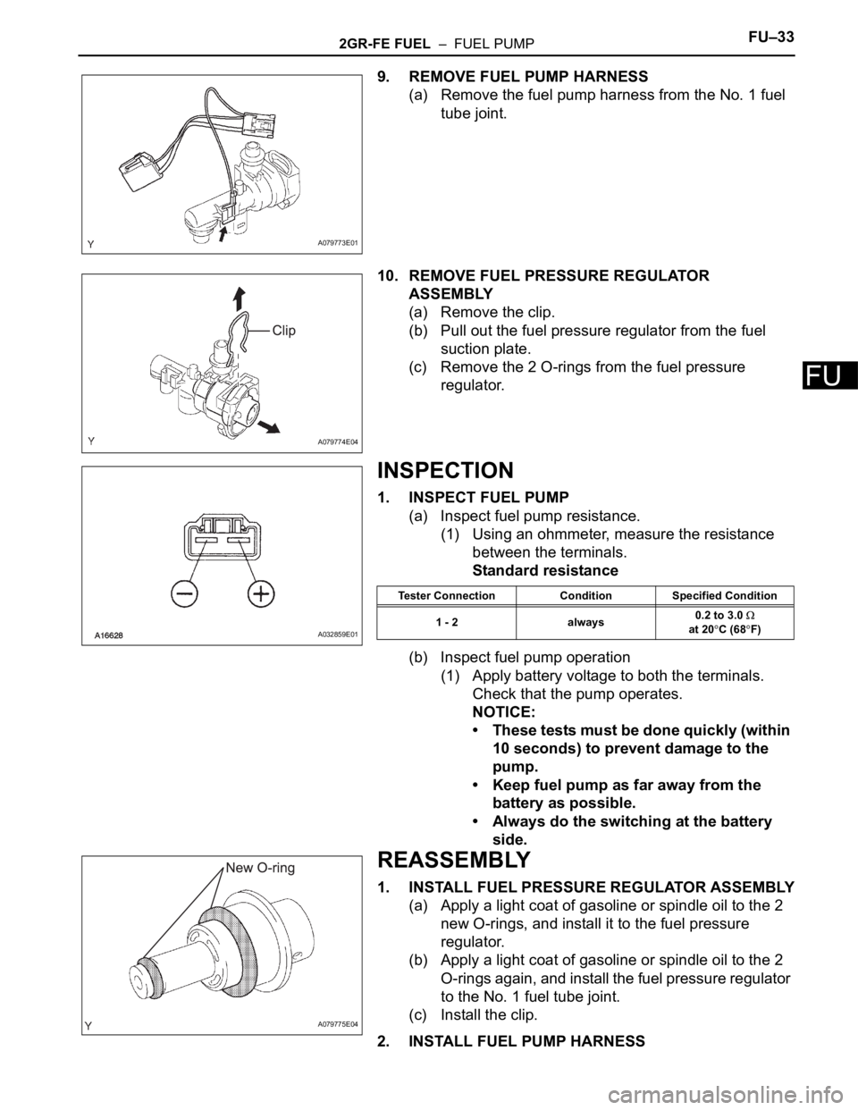
9. REMOVE FUEL PUMP HARNESS
(a) Remove the fuel pump harness from the No. 1 fuel
tube joint.
10. REMOVE FUEL PRESSURE REGULATOR
ASSEMBLY
(a) Remove the clip.
(b) Pull out the fuel pressure regulator from the fuel
suction plate.
(c) Remove the 2 O-rings from the fuel pressure
regulator.
INSPECTION
1. INSPECT FUEL PUMP
(a) Inspect fuel pump resistance.
(1) Using an ohmmeter, measure the resistance
between the terminals.
Standard resistance
(b) Inspect fuel pump operation
(1) Apply battery voltage to both the terminals.
Check that the pump operates.
NOTICE:
• These tests must be done quickly (within
10 seconds) to prevent damage to the
pump.
• Keep fuel pump as far away from the
battery as possible.
• Always do the switching at the battery
side.
REASSEMBLY
1. INSTALL FUEL PRESSURE REGULATOR ASSEMBLY
(a) Apply a light coat of gasoline or spindle oil to the 2
new O-rings, and install it to the fuel pressure
regulator.
(b) Apply a light coat of gasoline or spindle oil to the 2
O-rings again, and install the fuel pressure regulator
to the No. 1 fuel tube joint.
(c) Install the clip.
2. INSTALL FUEL PUMP HARNESS
A079773E01
A079774E04
A032859E01
Tester Connection Condition Specified Condition
1 - 2 always0.2 to 3.0
at 20
C (68F)
A079775E04
Page 1393 of 3000
AX–16U151E AUTOMATIC TRANSAXLE – AUTOMATIC TRANSAXLE SYSTEM
AX
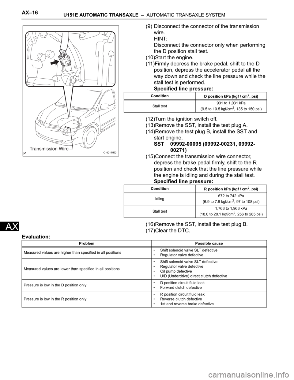
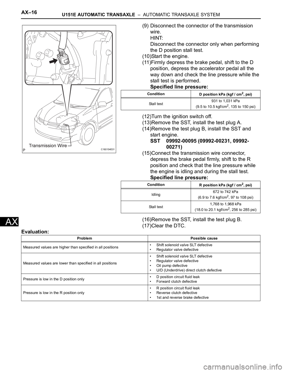
(9) Disconnect the connector of the transmission
wire.
HINT:
Disconnect the connector only when performing
the D position stall test.
(10)Start the engine.
(11)Firmly depress the brake pedal, shift to the D
position, depress the accelerator pedal all the
way down and check the line pressure while the
stall test is performed.
Specified line pressure:
(12)Turn the ignition switch off.
(13)Remove the SST, install the test plug A.
(14)Remove the test plug B, install the SST and
start engine.
SST 09992-00095 (09992-00231, 09992-
00271)
(15)Connect the transmission wire connector,
depress the brake pedal firmly, shift to the R
position and check that the line pressure while
the engine is idling and during the stall test.
Specified line pressure:
(16)Remove the SST, install the test plug B.
(17)Clear the DTC.
Evaluation:
C160154E01
Condition
D position kPa (kgf / cm2, psi)
Stall test931 to 1,031 kPa
(9.5 to 10.5 kgf/cm
2, 135 to 150 psi)
Condition
R position kPa (kgf / cm
2, psi)
Idling672 to 742 kPa
(6.9 to 7.6 kgf/cm
2, 97 to 108 psi)
Stall test1,768 to 1,968 kPa
(18.0 to 20.1 kgf/cm
2, 256 to 285 psi)
Problem Possible cause
Measured values are higher than specified in all positions• Shift solenoid valve SLT defective
• Regulator valve defective
Measured values are lower than specified in all positions• Shift solenoid valve SLT defective
• Regulator valve defective
• Oil pump defective
• U/D (Underdrive) direct clutch defective
Pressure is low in the D position only• D position circuit fluid leak
• Forward clutch defective
Pressure is low in the R position only• R position circuit fluid leak
• Reverse clutch defective
• 1st and reverse brake defective
Page 1483 of 3000
U151E AUTOMATIC TRANSAXLE – AUTOMATIC TRANSAXLE SYSTEMAX–117
AX
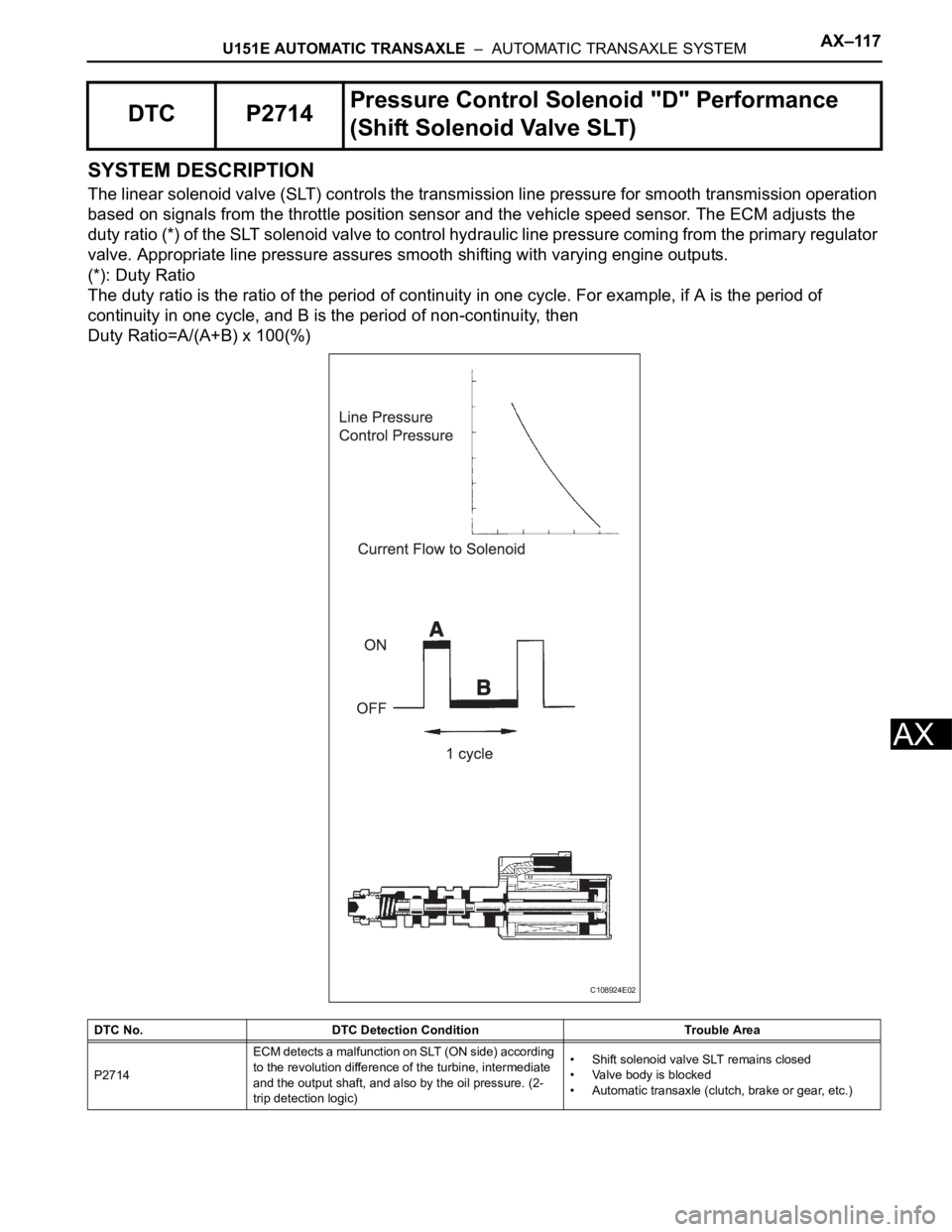
SYSTEM DESCRIPTION
The linear solenoid valve (SLT) controls the transmission line pressure for smooth transmission operation
based on signals from the throttle position sensor and the vehicle speed sensor. The ECM adjusts the
duty ratio (*) of the SLT solenoid valve to control hydraulic line pressure coming from the primary regulator
valve. Appropriate line pressure assures smooth shifting with varying engine outputs.
(*): Duty Ratio
The duty ratio is the ratio of the period of continuity in one cycle. For example, if A is the period of
continuity in one cycle, and B is the period of non-continuity, then
Duty Ratio=A/(A+B) x 100(%)
DTC P2714Pressure Control Solenoid "D" Performance
(Shift Solenoid Valve SLT)
DTC No. DTC Detection Condition Trouble Area
P2714ECM detects a malfunction on SLT (ON side) according
to the revolution difference of the turbine, intermediate
and the output shaft, and also by the oil pressure. (2-
trip detection logic)• Shift solenoid valve SLT remains closed
• Valve body is blocked
• Automatic transaxle (clutch, brake or gear, etc.)
C108924E02
Page 1489 of 3000
U151E AUTOMATIC TRANSAXLE – AUTOMATIC TRANSAXLE SYSTEMAX–123
AX
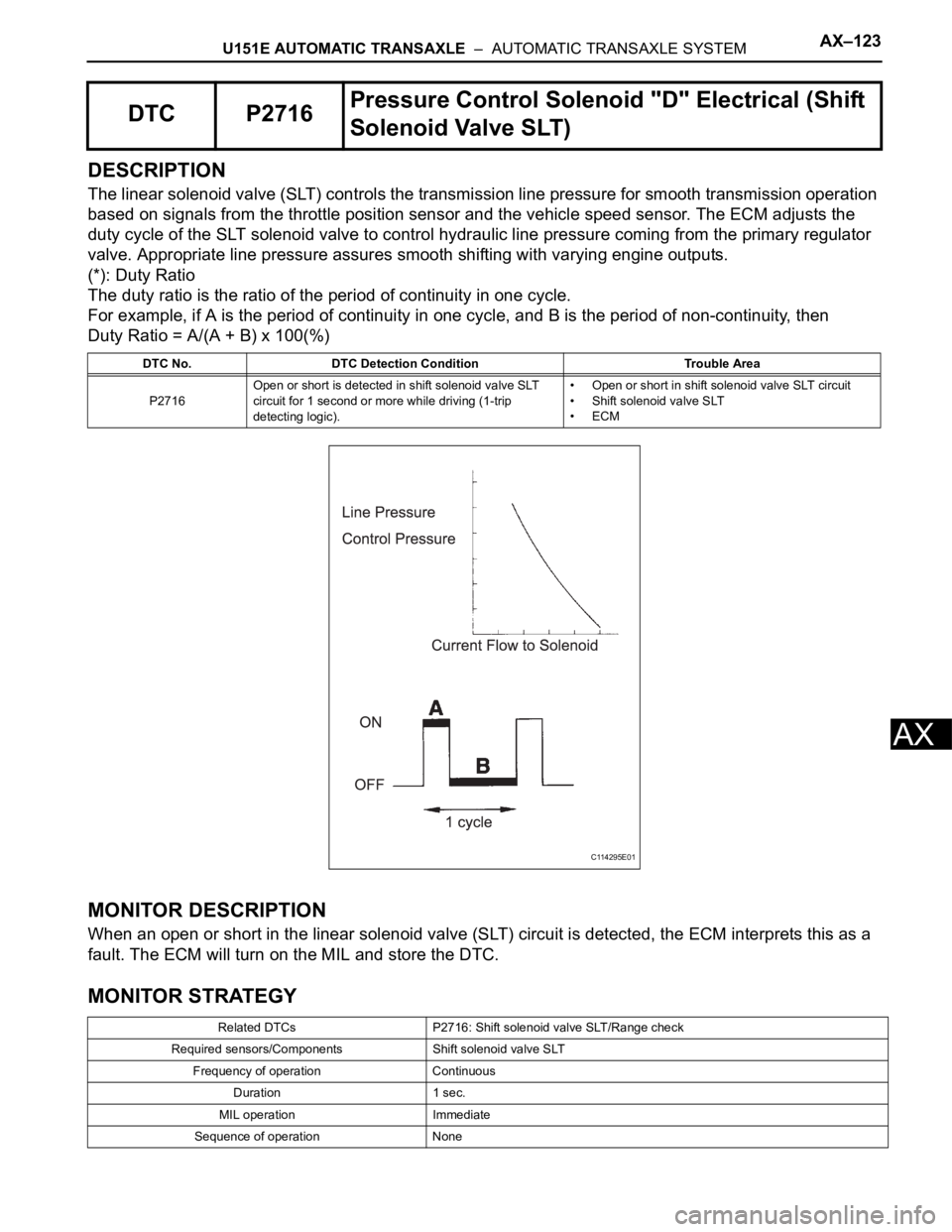
DESCRIPTION
The linear solenoid valve (SLT) controls the transmission line pressure for smooth transmission operation
based on signals from the throttle position sensor and the vehicle speed sensor. The ECM adjusts the
duty cycle of the SLT solenoid valve to control hydraulic line pressure coming from the primary regulator
valve. Appropriate line pressure assures smooth shifting with varying engine outputs.
(*): Duty Ratio
The duty ratio is the ratio of the period of continuity in one cycle.
For example, if A is the period of continuity in one cycle, and B is the period of non-continuity, then
Duty Ratio = A/(A + B) x 100(%)
MONITOR DESCRIPTION
When an open or short in the linear solenoid valve (SLT) circuit is detected, the ECM interprets this as a
fault. The ECM will turn on the MIL and store the DTC.
MONITOR STRATEGY
DTC P2716Pressure Control Solenoid "D" Electrical (Shift
Solenoid Valve SLT)
DTC No. DTC Detection Condition Trouble Area
P2716Open or short is detected in shift solenoid valve SLT
circuit for 1 second or more while driving (1-trip
detecting logic).• Open or short in shift solenoid valve SLT circuit
• Shift solenoid valve SLT
•ECM
Related DTCs P2716: Shift solenoid valve SLT/Range check
Required sensors/Components Shift solenoid valve SLT
Frequency of operation Continuous
Duration 1 sec.
MIL operation Immediate
Sequence of operation None
C114295E01
Page 1503 of 3000
AX–16U151E AUTOMATIC TRANSAXLE – AUTOMATIC TRANSAXLE SYSTEM
AX
(9) Disconnect the connector of the transmission
wire.
HINT:
Disconnect the connector only when performing
the D position stall test.
(10)Start the engine.
(11)Firmly depress the brake pedal, shift to the D
position, depress the accelerator pedal all the
way down and check the line pressure while the
stall test is performed.
Specified line pressure:
(12)Turn the ignition switch off.
(13)Remove the SST, install the test plug A.
(14)Remove the test plug B, install the SST and
start engine.
SST 09992-00095 (09992-00231, 09992-
00271)
(15)Connect the transmission wire connector,
depress the brake pedal firmly, shift to the R
position and check that the line pressure while
the engine is idling and during the stall test.
Specified line pressure:
(16)Remove the SST, install the test plug B.
(17)Clear the DTC.
Evaluation:
C160154E01
Condition
D position kPa (kgf / cm2, psi)
Stall test931 to 1,031 kPa
(9.5 to 10.5 kgf/cm
2, 135 to 150 psi)
Condition
R position kPa (kgf / cm
2, psi)
Idling672 to 742 kPa
(6.9 to 7.6 kgf/cm
2, 97 to 108 psi)
Stall test1,768 to 1,968 kPa
(18.0 to 20.1 kgf/cm
2, 256 to 285 psi)
Problem Possible cause
Measured values are higher than specified in all positions• Shift solenoid valve SLT defective
• Regulator valve defective
Measured values are lower than specified in all positions• Shift solenoid valve SLT defective
• Regulator valve defective
• Oil pump defective
• U/D (Underdrive) direct clutch defective
Pressure is low in the D position only• D position circuit fluid leak
• Forward clutch defective
Pressure is low in the R position only• R position circuit fluid leak
• Reverse clutch defective
• 1st and reverse brake defective
Page 1699 of 3000
AX–16U151F AUTOMATIC TRANSAXLE – AUTOMATIC TRANSAXLE SYSTEM
AX
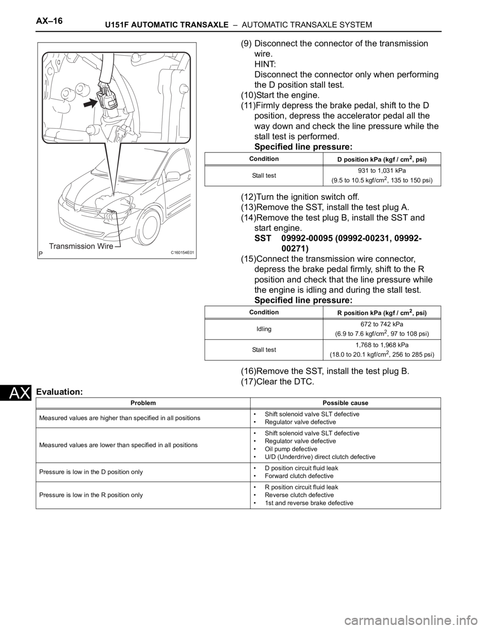
(9) Disconnect the connector of the transmission
wire.
HINT:
Disconnect the connector only when performing
the D position stall test.
(10)Start the engine.
(11)Firmly depress the brake pedal, shift to the D
position, depress the accelerator pedal all the
way down and check the line pressure while the
stall test is performed.
Specified line pressure:
(12)Turn the ignition switch off.
(13)Remove the SST, install the test plug A.
(14)Remove the test plug B, install the SST and
start engine.
SST 09992-00095 (09992-00231, 09992-
00271)
(15)Connect the transmission wire connector,
depress the brake pedal firmly, shift to the R
position and check that the line pressure while
the engine is idling and during the stall test.
Specified line pressure:
(16)Remove the SST, install the test plug B.
(17)Clear the DTC.
Evaluation:
C160154E01
Condition
D position kPa (kgf / cm2, psi)
Stall test931 to 1,031 kPa
(9.5 to 10.5 kgf/cm
2, 135 to 150 psi)
Condition
R position kPa (kgf / cm
2, psi)
Idling672 to 742 kPa
(6.9 to 7.6 kgf/cm
2, 97 to 108 psi)
Stall test1,768 to 1,968 kPa
(18.0 to 20.1 kgf/cm
2, 256 to 285 psi)
Problem Possible cause
Measured values are higher than specified in all positions• Shift solenoid valve SLT defective
• Regulator valve defective
Measured values are lower than specified in all positions• Shift solenoid valve SLT defective
• Regulator valve defective
• Oil pump defective
• U/D (Underdrive) direct clutch defective
Pressure is low in the D position only• D position circuit fluid leak
• Forward clutch defective
Pressure is low in the R position only• R position circuit fluid leak
• Reverse clutch defective
• 1st and reverse brake defective
Page 1789 of 3000
U151F AUTOMATIC TRANSAXLE – AUTOMATIC TRANSAXLE SYSTEMAX–117
AX
SYSTEM DESCRIPTION
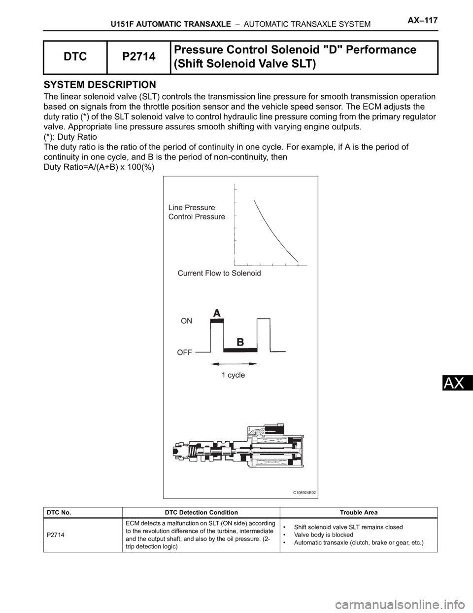
The linear solenoid valve (SLT) controls the transmission line pressure for smooth transmission operation
based on signals from the throttle position sensor and the vehicle speed sensor. The ECM adjusts the
duty ratio (*) of the SLT solenoid valve to control hydraulic line pressure coming from the primary regulator
valve. Appropriate line pressure assures smooth shifting with varying engine outputs.
(*): Duty Ratio
The duty ratio is the ratio of the period of continuity in one cycle. For example, if A is the period of
continuity in one cycle, and B is the period of non-continuity, then
Duty Ratio=A/(A+B) x 100(%)
DTC P2714Pressure Control Solenoid "D" Performance
(Shift Solenoid Valve SLT)
DTC No. DTC Detection Condition Trouble Area
P2714ECM detects a malfunction on SLT (ON side) according
to the revolution difference of the turbine, intermediate
and the output shaft, and also by the oil pressure. (2-
trip detection logic)• Shift solenoid valve SLT remains closed
• Valve body is blocked
• Automatic transaxle (clutch, brake or gear, etc.)
C108924E02
Page 1795 of 3000
U151F AUTOMATIC TRANSAXLE – AUTOMATIC TRANSAXLE SYSTEMAX–123
AX
DESCRIPTION
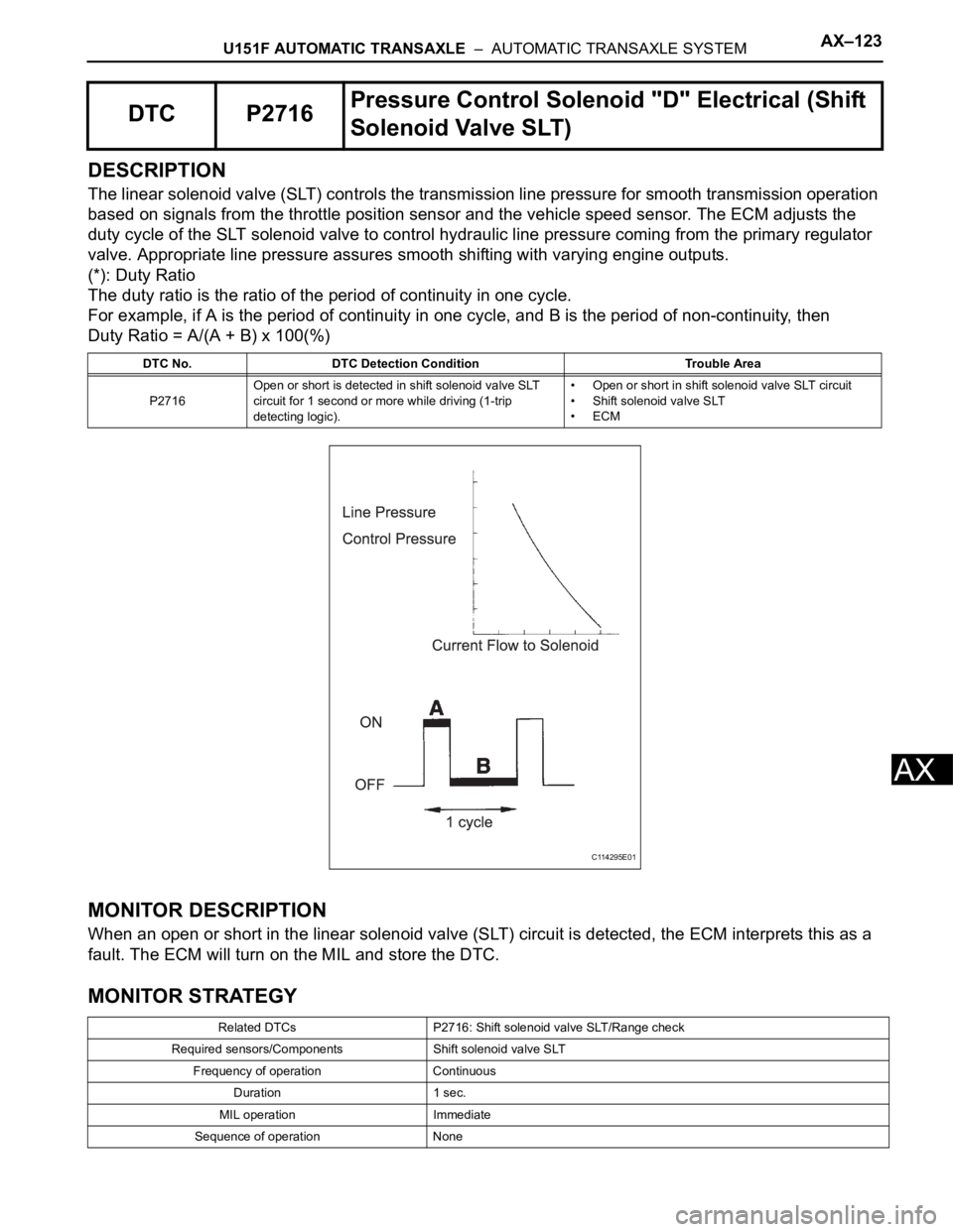
The linear solenoid valve (SLT) controls the transmission line pressure for smooth transmission operation
based on signals from the throttle position sensor and the vehicle speed sensor. The ECM adjusts the
duty cycle of the SLT solenoid valve to control hydraulic line pressure coming from the primary regulator
valve. Appropriate line pressure assures smooth shifting with varying engine outputs.
(*): Duty Ratio
The duty ratio is the ratio of the period of continuity in one cycle.
For example, if A is the period of continuity in one cycle, and B is the period of non-continuity, then
Duty Ratio = A/(A + B) x 100(%)
MONITOR DESCRIPTION
When an open or short in the linear solenoid valve (SLT) circuit is detected, the ECM interprets this as a
fault. The ECM will turn on the MIL and store the DTC.
MONITOR STRATEGY
DTC P2716Pressure Control Solenoid "D" Electrical (Shift
Solenoid Valve SLT)
DTC No. DTC Detection Condition Trouble Area
P2716Open or short is detected in shift solenoid valve SLT
circuit for 1 second or more while driving (1-trip
detecting logic).• Open or short in shift solenoid valve SLT circuit
• Shift solenoid valve SLT
•ECM
Related DTCs P2716: Shift solenoid valve SLT/Range check
Required sensors/Components Shift solenoid valve SLT
Frequency of operation Continuous
Duration 1 sec.
MIL operation Immediate
Sequence of operation None
C114295E01