Page 463 of 3000

2GR-FE ENGINE CONTROL SYSTEM – SFI SYSTEMES–157
ES
WIRING DIAGRAM
INSPECTION PROCEDURE
HINT:
• If other DTCs relating to different systems that have terminal E2 as the ground terminal are output
simultaneously, terminal E2 may have an open circuit.
• Read freeze frame data using the intelligent tester. The ECM records vehicle and driving condition
information as freeze frame data the moment a DTC is stored. When troubleshooting, freeze frame
data can be helpful in determining whether the vehicle was running or stopped, whether the engine
was warmed up or not, whether the air-fuel ratio was lean or rich, as well as other data recorded at the
time of a malfunction.
(a) Connect the intelligent tester to the DLC3.
(b) Turn the ignition switch to the ON position and turn the
intelligent tester on.
(c) Select the following menu items: DIAGNOSIS /
ENHANCED OBD II / DATA LIST / ETCS / THROTTLE
POS and THROTTLE POS #2.
(d) Check the values displayed on the tester.
Result
1READ VALUE OF INTELLIGENT TESTER (THROTTLE POS AND THROTTLE POS #2)
A085458E27
TP#1 (VTA1)
When AP ReleasedTP#2 (VTA2)
When AP ReleasedTP#1 (VTA1)
When AP
DepressedTP#2 (VTA2)
When AP
DepressedTrouble Area Proceed to
0%Between 0 V and 0.2
V0%Between 0 V and 0.2
VVC circuit open A
100%Between 4.5 V and
5.0 V100 %Between 4.5 V and
5.0 VE2 circuit open A
0% or 100%Between 2.1 V and
3.1 V
(Fail-safe)0% or 100%Between 2.1 V and
3.1 V
(Fail-safe)VTA1 circuit open or
ground shortA
Page 468 of 3000

ES–1622GR-FE ENGINE CONTROL SYSTEM – SFI SYSTEM
ES
DESCRIPTION
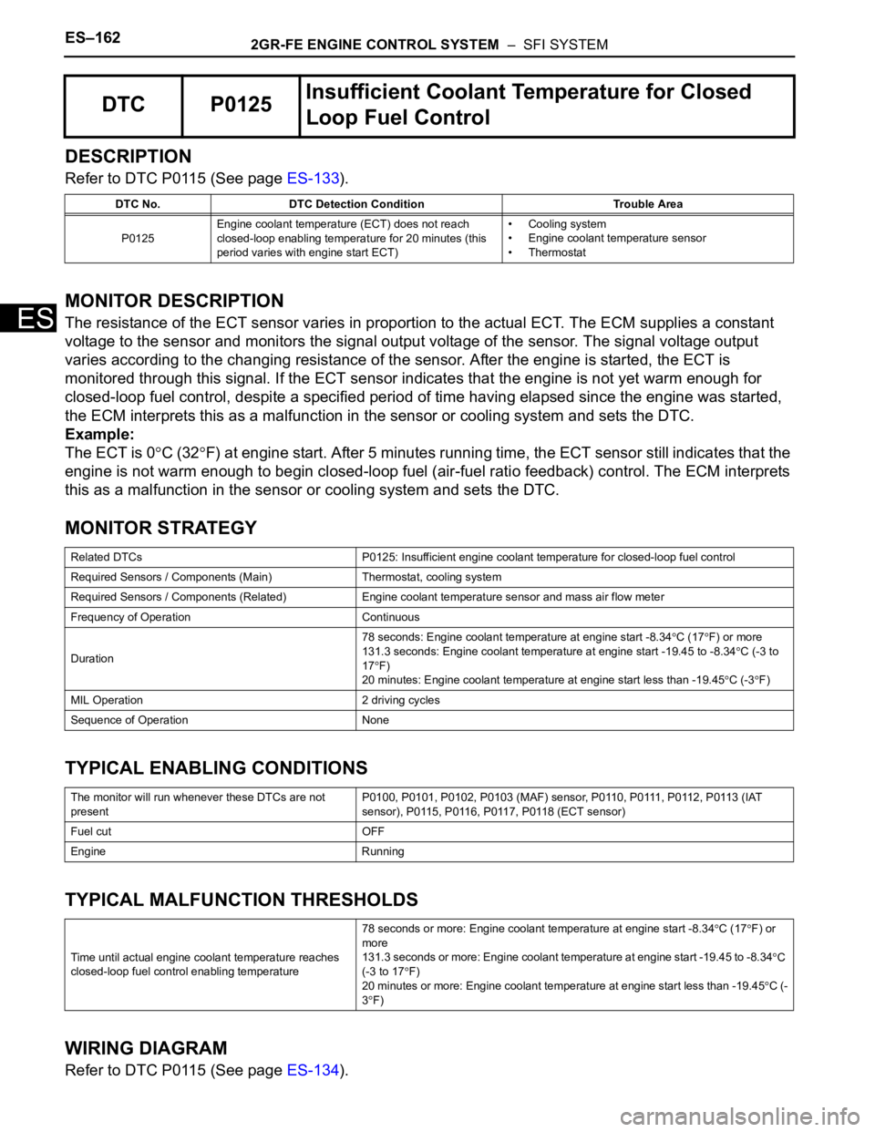
Refer to DTC P0115 (See page ES-133).
MONITOR DESCRIPTION
The resistance of the ECT sensor varies in proportion to the actual ECT. The ECM supplies a constant
voltage to the sensor and monitors the signal output voltage of the sensor. The signal voltage output
varies according to the changing resistance of the sensor. After the engine is started, the ECT is
monitored through this signal. If the ECT sensor indicates that the engine is not yet warm enough for
closed-loop fuel control, despite a specified period of time having elapsed since the engine was started,
the ECM interprets this as a malfunction in the sensor or cooling system and sets the DTC.
Example:
The ECT is 0
C (32F) at engine start. After 5 minutes running time, the ECT sensor still indicates that the
engine is not warm enough to begin closed-loop fuel (air-fuel ratio feedback) control. The ECM interprets
this as a malfunction in the sensor or cooling system and sets the DTC.
MONITOR STRATEGY
TYPICAL ENABLING CONDITIONS
TYPICAL MALFUNCTION THRESHOLDS
WIRING DIAGRAM
Refer to DTC P0115 (See page ES-134).
DTC P0125Insufficient Coolant Temperature for Closed
Loop Fuel Control
DTC No. DTC Detection Condition Trouble Area
P0125Engine coolant temperature (ECT) does not reach
closed-loop enabling temperature for 20 minutes (this
period varies with engine start ECT)• Cooling system
• Engine coolant temperature sensor
• Thermostat
Related DTCs P0125: Insufficient engine coolant temperature for closed-loop fuel control
Required Sensors / Components (Main) Thermostat, cooling system
Required Sensors / Components (Related) Engine coolant temperature sensor and mass air flow meter
Frequency of Operation Continuous
Duration78 seconds: Engine coolant temperature at engine start -8.34
C (17F) or more
131.3 seconds: Engine coolant temperature at engine start -19.45 to -8.34C (-3 to
17
F)
20 minutes: Engine coolant temperature at engine start less than -19.45
C (-3F)
MIL Operation 2 driving cycles
Sequence of Operation None
The monitor will run whenever these DTCs are not
presentP0100, P0101, P0102, P0103 (MAF) sensor, P0110, P0111, P0112, P0113 (IAT
sensor), P0115, P0116, P0117, P0118 (ECT sensor)
Fuel cut OFF
Engine Running
Time until actual engine coolant temperature reaches
closed-loop fuel control enabling temperature78 seconds or more: Engine coolant temperature at engine start -8.34
C (17F) or
more
131.3 seconds or more: Engine coolant temperature at engine start -19.45 to -8.34
C
(-3 to 17
F)
20 minutes or more: Engine coolant temperature at engine start less than -19.45C (-
3
F)
Page 481 of 3000
2GR-FE ENGINE CONTROL SYSTEM – SFI SYSTEMES–175
ES
WIRING DIAGRAM
A136092E05
Page 496 of 3000

ES–1902GR-FE ENGINE CONTROL SYSTEM – SFI SYSTEM
ES
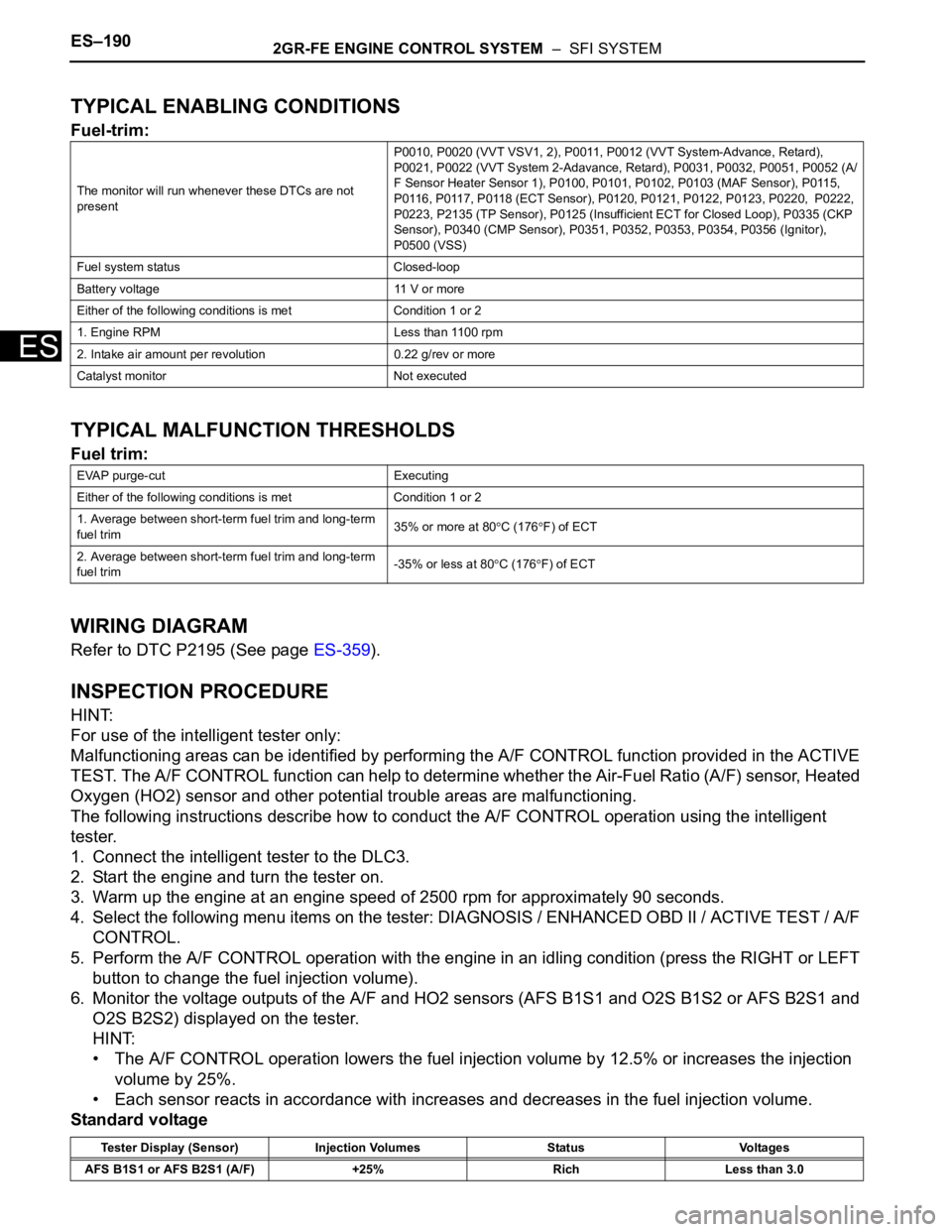
TYPICAL ENABLING CONDITIONS
Fuel-trim:
TYPICAL MALFUNCTION THRESHOLDS
Fuel trim:
WIRING DIAGRAM
Refer to DTC P2195 (See page ES-359).
INSPECTION PROCEDURE
HINT:
For use of the intelligent tester only:
Malfunctioning areas can be identified by performing the A/F CONTROL function provided in the ACTIVE
TEST. The A/F CONTROL function can help to determine whether the Air-Fuel Ratio (A/F) sensor, Heated
Oxygen (HO2) sensor and other potential trouble areas are malfunctioning.
The following instructions describe how to conduct the A/F CONTROL operation using the intelligent
tester.
1. Connect the intelligent tester to the DLC3.
2. Start the engine and turn the tester on.
3. Warm up the engine at an engine speed of 2500 rpm for approximately 90 seconds.
4. Select the following menu items on the tester: DIAGNOSIS / ENHANCED OBD II / ACTIVE TEST / A/F
CONTROL.
5. Perform the A/F CONTROL operation with the engine in an idling condition (press the RIGHT or LEFT
button to change the fuel injection volume).
6. Monitor the voltage outputs of the A/F and HO2 sensors (AFS B1S1 and O2S B1S2 or AFS B2S1 and
O2S B2S2) displayed on the tester.
HINT:
• The A/F CONTROL operation lowers the fuel injection volume by 12.5% or increases the injection
volume by 25%.
• Each sensor reacts in accordance with increases and decreases in the fuel injection volume.
Standard voltage
The monitor will run whenever these DTCs are not
presentP0010, P0020 (VVT VSV1, 2), P0011, P0012 (VVT System-Advance, Retard),
P0021, P0022 (VVT System 2-Adavance, Retard), P0031, P0032, P0051, P0052 (A/
F Sensor Heater Sensor 1), P0100, P0101, P0102, P0103 (MAF Sensor), P0115,
P0116, P0117, P0118 (ECT Sensor), P0120, P0121, P0122, P0123, P0220, P0222,
P0223, P2135 (TP Sensor), P0125 (Insufficient ECT for Closed Loop), P0335 (CKP
Sensor), P0340 (CMP Sensor), P0351, P0352, P0353, P0354, P0356 (Ignitor),
P0500 (VSS)
Fuel system status Closed-loop
Battery voltage 11 V or more
Either of the following conditions is met Condition 1 or 2
1. Engine RPM Less than 1100 rpm
2. Intake air amount per revolution 0.22 g/rev or more
Catalyst monitor Not executed
EVAP purge-cut Executing
Either of the following conditions is met Condition 1 or 2
1. Average between short-term fuel trim and long-term
fuel trim35% or more at 80
C (176F) of ECT
2. Average between short-term fuel trim and long-term
fuel trim-35% or less at 80
C (176F) of ECT
Tester Display (Sensor) Injection Volumes Status Voltages
AFS B1S1 or AFS B2S1 (A/F) +25% Rich Less than 3.0
Page 507 of 3000
2GR-FE ENGINE CONTROL SYSTEM – SFI SYSTEMES–201
ES
WIRING DIAGRAM
This troubleshooting procedure is based on the premise that the engine is started. If the engine is not
started, proceed to the problem symptoms table (See page ES-27).
INSPECTION PROCEDURE
(a) Connect the intelligent tester to the DLC3.
1PERFORM ACTIVE TEST BY INTELLIGENT TESTER
A162641E03
Page 512 of 3000
ES–2062GR-FE ENGINE CONTROL SYSTEM – SFI SYSTEM
ES
Monitor period of catalyst-damage-misfire (MIL blinks):
TYPICAL MALFUNCTION THRESHOLDS
Monitor period of emission-related-misfire:
Monitor period of catalyst-damage-misfire (MIL blinks):
MONITOR RESULT
Refer to CHECKING MONITOR STATUS (See page ES-19).
WIRING DIAGRAM
Refer to DTC P0351 for wiring diagram of the ignition system (See page ES-238).
Except above Crankshaft 1000 revolutions x 4
All of the following conditions 1, 2 and 3 are met Crankshaft 200 revolutions
1. Driving cycle 1st
2. Check mode OFF
3. Engine RPM Less than 2600 rpm
Except above (MIL blinks immediately) Crankshaft 200 revolutions x 3
Misfire rate 1% or more
Number of misfire per 200 revolutions 94 or more (varies with intake air amount and RPM)
Paired cylinders misfire (MIL blinks immediately) Detected
Page 529 of 3000
2GR-FE ENGINE CONTROL SYSTEM – SFI SYSTEMES–223
ES
WIRING DIAGRAM
INSPECTION PROCEDURE
HINT:
• DTCs P0327 and P0328 are for the bank 1 knock sensor circuit.
• DTCs P0332 and P0333 are for the bank 2 knock sensor circuit.
• Read freeze frame data using the intelligent tester. The ECM records vehicle and driving condition
information as freeze frame data the moment a DTC is stored. When troubleshooting, freeze frame
data can be helpful in determining whether the vehicle was running or stopped, whether the engine
was warmed up or not, whether the air-fuel ratio was lean or rich, as well as other data recorded at the
time of a malfunction.
A136096E05
Page 536 of 3000
ES–2302GR-FE ENGINE CONTROL SYSTEM – SFI SYSTEM
ES
WIRING DIAGRAM
A136097E06