Page 691 of 3000

ES–3982GR-FE ENGINE CONTROL SYSTEM – SFI SYSTEM
ES
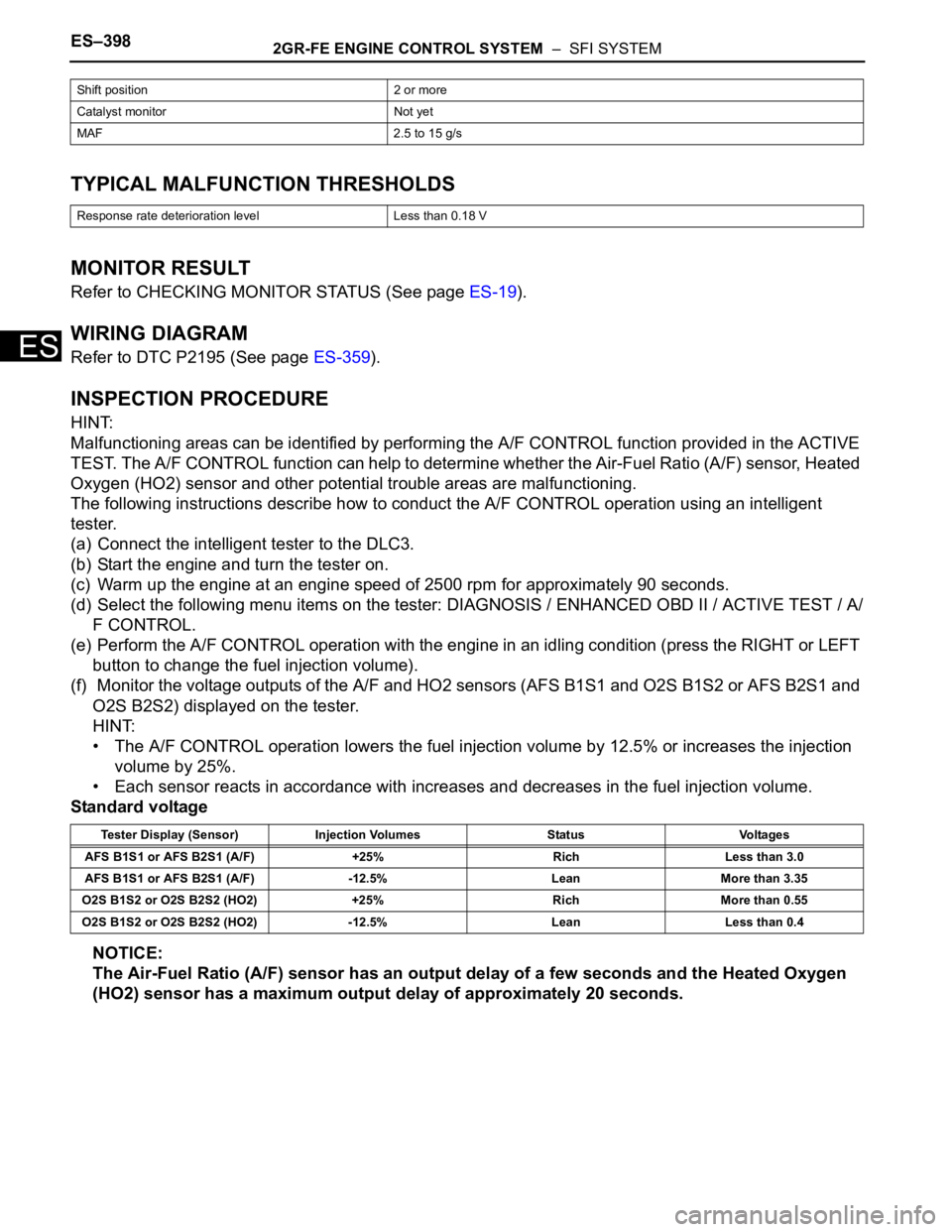
TYPICAL MALFUNCTION THRESHOLDS
MONITOR RESULT
Refer to CHECKING MONITOR STATUS (See page ES-19).
WIRING DIAGRAM
Refer to DTC P2195 (See page ES-359).
INSPECTION PROCEDURE
HINT:
Malfunctioning areas can be identified by performing the A/F CONTROL function provided in the ACTIVE
TEST. The A/F CONTROL function can help to determine whether the Air-Fuel Ratio (A/F) sensor, Heated
Oxygen (HO2) sensor and other potential trouble areas are malfunctioning.
The following instructions describe how to conduct the A/F CONTROL operation using an intelligent
tester.
(a) Connect the intelligent tester to the DLC3.
(b) Start the engine and turn the tester on.
(c) Warm up the engine at an engine speed of 2500 rpm for approximately 90 seconds.
(d) Select the following menu items on the tester: DIAGNOSIS / ENHANCED OBD II / ACTIVE TEST / A/
F CONTROL.
(e) Perform the A/F CONTROL operation with the engine in an idling condition (press the RIGHT or LEFT
button to change the fuel injection volume).
(f) Monitor the voltage outputs of the A/F and HO2 sensors (AFS B1S1 and O2S B1S2 or AFS B2S1 and
O2S B2S2) displayed on the tester.
HINT:
• The A/F CONTROL operation lowers the fuel injection volume by 12.5% or increases the injection
volume by 25%.
• Each sensor reacts in accordance with increases and decreases in the fuel injection volume.
Standard voltage
NOTICE:
The Air-Fuel Ratio (A/F) sensor has an output delay of a few seconds and the Heated Oxygen
(HO2) sensor has a maximum output delay of approximately 20 seconds.
Shift position 2 or more
Catalyst monitor Not yet
MAF 2.5 to 15 g/s
Response rate deterioration level Less than 0.18 V
Tester Display (Sensor) Injection Volumes Status Voltages
AFS B1S1 or AFS B2S1 (A/F) +25% Rich Less than 3.0
AFS B1S1 or AFS B2S1 (A/F) -12.5% Lean More than 3.35
O2S B1S2 or O2S B2S2 (HO2) +25% Rich More than 0.55
O2S B1S2 or O2S B2S2 (HO2) -12.5% Lean Less than 0.4
Page 706 of 3000
ES–4202GR-FE ENGINE CONTROL SYSTEM – SFI SYSTEM
ES
WIRING DIAGRAM
Refer to DTC P0450 (See page ES-272).
INSPECTION PROCEDURE
NOTICE:
An intelligent tester is required to conduct the following diagnostic troubleshooting procedure.
HINT:
• Using intelligent tester monitor results enables the EVAP (Evaporative Emission) system to be
confirmed.
• Read freeze frame data using the intelligent tester. The ECM records vehicle and driving condition
information as freeze frame data the moment a DTC is stored. When troubleshooting, freeze frame
data can be helpful in determining whether the vehicle was running or stopped, whether the engine
was warmed up or not, whether the air-fuel ratio was lean or rich, as well as other data recorded at the
time of a malfunction.
(a) Turn the ignition switch off and wait for 10 seconds.
(b) Turn the ignition switch to the ON position.
1CONFIRM DTC
A118976E04
Page 731 of 3000
2GR-FE ENGINE CONTROL SYSTEM – SFI SYSTEMES–445
ES
DESCRIPTION
When the ignition switch is turned to the ON position, the battery voltage is applied to terminal IGSW of
the ECM. The ECM MREL output signal causes a current to flow to the coil, closing the contacts of the EFI
relay and supplying power to terminal +B of the ECM.
If the ignition switch is turned off, the ECM holds the EFI relay ON for a maximum of 2 seconds to allow for
the initial setting of the throttle valve.
WIRING DIAGRAM
ECM Power Source Circuit
A136865E04
Page 739 of 3000
2GR-FE ENGINE CONTROL SYSTEM – SFI SYSTEMES–453
ES
WIRING DIAGRAM
A163161E02
Page 746 of 3000
ES–4602GR-FE ENGINE CONTROL SYSTEM – SFI SYSTEM
ES
WIRING DIAGRAM
INSPECTION PROCEDURE
(a) Check if there is pressure in the fuel inlet hose.
HINT:
If there is fuel pressure, the sound of fuel flowing will be
heard.
1CHECK FUEL PUMP
A162641E03
Page 755 of 3000
2GR-FE ENGINE CONTROL SYSTEM – SFI SYSTEMES–469
ES
DESCRIPTION
The system detects the ignition switch's starting signal (STSW) and then supplies current to the starter
until the ECM judges that the engine has started successfully. The purpose is to reduce the holding time
of the ignition key.
WIRING DIAGRAM
Refer to DTC P0617 (See page ES-320).
INSPECTION PROCEDURE
(a) When starting the engine, check whether the starter
motor starts.
OK:
Engine is cranking.
Cranking Holding Function Circuit
1CHECK CRANKING
A166695E01
Page 765 of 3000
2GR-FE ENGINE CONTROL SYSTEM – SFI SYSTEMES–479
ES
WIRING DIAGRAM
INSPECTION PROCEDURE
(a) Connect the intelligent tester to the DLC3.
(b) Start the engine and turn the intelligent tester on.
(c) Select the following menu items: DIAGNOSIS /
ENHANCED OBD II / ACTIVE TEST / INTAKE CTL
VSV1. Operate the VSV for AICS.
OK:
Operational noise can be heard.
OK
NG
(a) Disconnect the V14 VSV for ACIS connector.
(b) Apply battery voltage between the terminals of the air
intake valve connector.
(c) Check the air intake valve operation.
OK:
Operational noise can be heard.
(d) Reconnect the VSV for ACIS connector.
NG
1PERFORM ACTIVE TEST BY INTELLIGENT TESTER (OPERATE VSV FOR ACIS)
A136867E19
PROCEED TO NEXT CIRCUIT INSPECTION
SHOWN IN PROBLEM SYMPTOMS TABLE
2CHECK INTAKE AIR CONTROL VALVE (OPERATION)
E121181E09
REPLACE INTAKE AIR SURGE TANK
Page 768 of 3000

ES–4862GR-FE ENGINE CONTROL SYSTEM – SFI SYSTEM
ES
DESCRIPTION
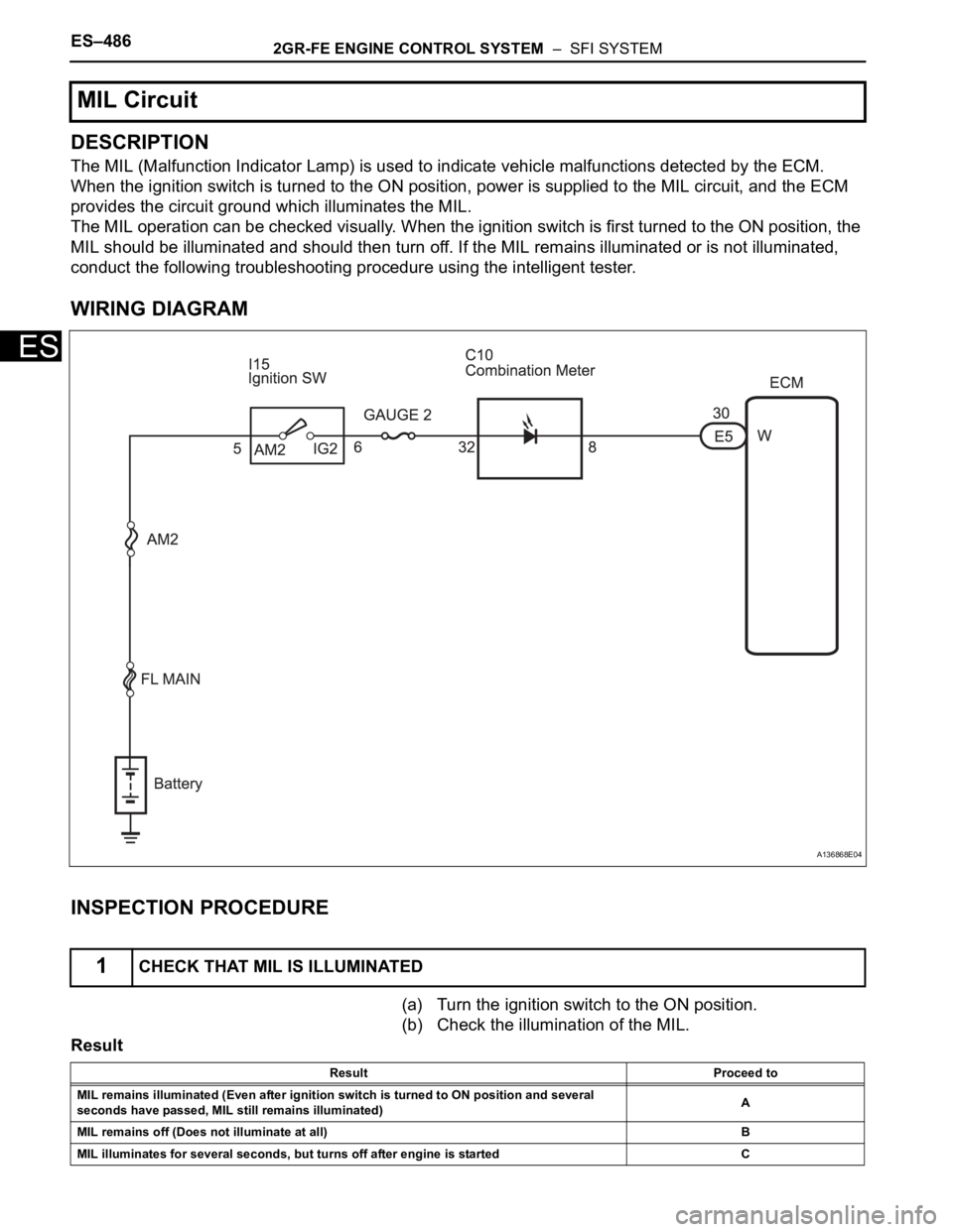
The MIL (Malfunction Indicator Lamp) is used to indicate vehicle malfunctions detected by the ECM.
When the ignition switch is turned to the ON position, power is supplied to the MIL circuit, and the ECM
provides the circuit ground which illuminates the MIL.
The MIL operation can be checked visually. When the ignition switch is first turned to the ON position, the
MIL should be illuminated and should then turn off. If the MIL remains illuminated or is not illuminated,
conduct the following troubleshooting procedure using the intelligent tester.
WIRING DIAGRAM
INSPECTION PROCEDURE
(a) Turn the ignition switch to the ON position.
(b) Check the illumination of the MIL.
Result
MIL Circuit
1CHECK THAT MIL IS ILLUMINATED
A136868E04
Result Proceed to
MIL remains illuminated (Even after ignition switch is turned to ON position and several
seconds have passed, MIL still remains illuminated)A
MIL remains off (Does not illuminate at all)B
MIL illuminates for several seconds, but turns off after engine is started C