Page 1474 of 3000
AX–108U151E AUTOMATIC TRANSAXLE – AUTOMATIC TRANSAXLE SYSTEM
AX
WIRING DIAGRAM
INSPECTION PROCEDURE
(a) Disconnect the transmission wire connector from the
transaxle.
(b) Measure the resistance according to the value(s) in the
table below.
Standard resistance
(c) Measure the resistance according to the value(s) in the
table below.
Standard resistance (Check for short)
NG
OK
1INSPECT TRANSMISSION WIRE (SL3)
G031765E60
C113969E05
Tester ConnectionSpecified Condition
20C (68F)
4 (SL3+) - 11 (SL3-) 5.0 to 5.6
Tester Connection Specified Condition
4 (SL3+) - Body ground 10 k
or higher
11 (SL3-) - Body ground
Go to step 3
Page 1478 of 3000
AX–112U151E AUTOMATIC TRANSAXLE – AUTOMATIC TRANSAXLE SYSTEM
AX
TYPICAL MALFUNCTION THRESHOLDS
P0982: Range check (Low resistance):
P0983: Range check (High resistance):
COMPONENT OPERATING RANGE
WIRING DIAGRAM
INSPECTION PROCEDURE
(a) Disconnect the transmission wire connector from the
transaxle.
(b) Measure the resistance according to the value(s) in the
table below.
Standard resistance
NG
OK
Shift solenoid valve S4 resistance 8 or less
Shift solenoid valve S4 resistance 100 k
or more
Shift solenoid valve S4 Resistance: 11 to 15
at 20C (68F)
1INSPECT TRANSMISSION WIRE (S4)
G031165E82
C113969E07
Tester ConnectionSpecified Condition
20C (68F)
3 (S4) - Body ground 11 to 15
Go to step 3
Page 1481 of 3000
U151E AUTOMATIC TRANSAXLE – AUTOMATIC TRANSAXLE SYSTEMAX–115
AX
TYPICAL MALFUNCTION THRESHOLDS
P0985: Range check (Low resistance):
P0986: Range check (High resistance):
COMPONENT OPERATING RANGE
WIRING DIAGRAM
INSPECTION PROCEDURE
(a) Disconnect the transmission wire connector from the
transaxle.
(b) Measure the resistance according to the value(s) in the
table below.
Standard resistance
NG
OK
Shift solenoid valve SR resistance 8 or less
Shift solenoid valve SR resistance 100 k
or more
Shift solenoid valve SR Resistance: 11 to 15
at 20C (68F)
1INSPECT TRANSMISSION WIRE (SR)
G031165E83
C113969E08
Tester ConnectionSpecified Condition
20C (68F)
9 (SR) - Body ground 11 to 15
Go to step 3
Page 1490 of 3000
AX–124U151E AUTOMATIC TRANSAXLE – AUTOMATIC TRANSAXLE SYSTEM
AX
TYPICAL ENABLING CONDITIONS
TYPICAL MALFUNCTION THRESHOLDS
COMPONENT OPERATING RANGE
WIRING DIAGRAM
The monitor will run whenever this DTC is not present. None
Solenoid current cut status Not cut
Battery voltage11 V or more
Ignition switchON
StarterOFF
CPU commanded duty ratio to SLT 19% or more
Solenoid status from IC Fail (Open or short)
Shift solenoid valve SLT Resistance: 5.0 to 5.6
at 20C (68F)
G031770E39
Page 1494 of 3000
AX–128U151E AUTOMATIC TRANSAXLE – AUTOMATIC TRANSAXLE SYSTEM
AX
TYPICAL MALFUNCTION THRESHOLDS
P2769: Range check (Low resistance):
P2770: Range check (High resistance):
COMPONENT OPERATING RANGE
WIRING DIAGRAM
INSPECTION PROCEDURE
(a) Disconnect the transmission wire connector from the
transaxle.
(b) Measure the resistance according to the value(s) in the
table below.
Standard resistance
NG
StarterOFF
Shift solenoid valve DSL resistance 8
or less
Shift solenoid valve DSL resistance 100 k
or more
Shift solenoid valve DSL Resistance: 11 to 13
at 20C (68F)
1INSPECT TRANSMISSION WIRE (DSL)
G031165E84
C113969E11
Tester ConnectionSpecified Condition
20C (68F)
10 (DSL) - Body ground 11 to 13
Go to step 3
Page 1719 of 3000
U151F AUTOMATIC TRANSAXLE – AUTOMATIC TRANSAXLE SYSTEMAX–47
AX
WIRING DIAGRAM
C160583E01
Page 1724 of 3000

AX–52U151F AUTOMATIC TRANSAXLE – AUTOMATIC TRANSAXLE SYSTEM
AX
COMPONENT OPERATING RANGE
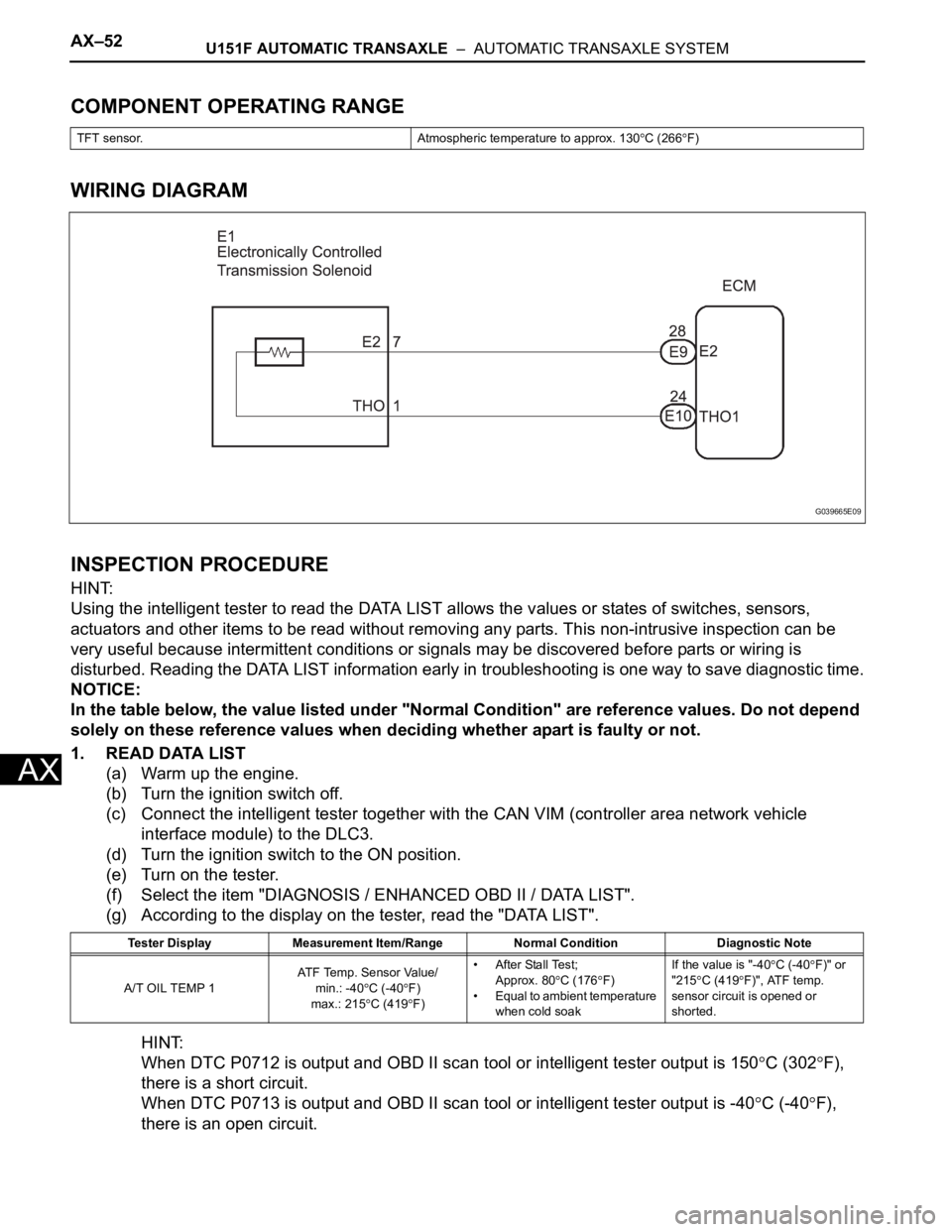
WIRING DIAGRAM
INSPECTION PROCEDURE
HINT:
Using the intelligent tester to read the DATA LIST allows the values or states of switches, sensors,
actuators and other items to be read without removing any parts. This non-intrusive inspection can be
very useful because intermittent conditions or signals may be discovered before parts or wiring is
disturbed. Reading the DATA LIST information early in troubleshooting is one way to save diagnostic time.
NOTICE:
In the table below, the value listed under "Normal Condition" are reference values. Do not depend
solely on these reference values when deciding whether apart is faulty or not.
1. READ DATA LIST
(a) Warm up the engine.
(b) Turn the ignition switch off.
(c) Connect the intelligent tester together with the CAN VIM (controller area network vehicle
interface module) to the DLC3.
(d) Turn the ignition switch to the ON position.
(e) Turn on the tester.
(f) Select the item "DIAGNOSIS / ENHANCED OBD II / DATA LIST".
(g) According to the display on the tester, read the "DATA LIST".
HINT:
When DTC P0712 is output and OBD II scan tool or intelligent tester output is 150
C (302F),
there is a short circuit.
When DTC P0713 is output and OBD II scan tool or intelligent tester output is -40
C (-40F),
there is an open circuit.
TFT sensor. Atmospheric temperature to approx. 130C (266F)
Tester Display Measurement Item/Range Normal Condition Diagnostic Note
A/T OIL TEMP 1AT F Te m p . S e n s o r Va l u e /
min.: -40
C (-40F)
max.: 215
C (419F)• After Stall Test;
Approx. 80
C (176F)
• Equal to ambient temperature
when cold soakIf the value is "-40
C (-40F)" or
"215
C (419F)", ATF temp.
sensor circuit is opened or
shorted.
G039665E09
Page 1728 of 3000

AX–56U151F AUTOMATIC TRANSAXLE – AUTOMATIC TRANSAXLE SYSTEM
AX
Condition (C):
Condition (D):
TYPICAL MALFUNCTION THRESHOLDS
Condition (A), (B), (C):
Condition (D):
COMPONENT OPERATING RANGE
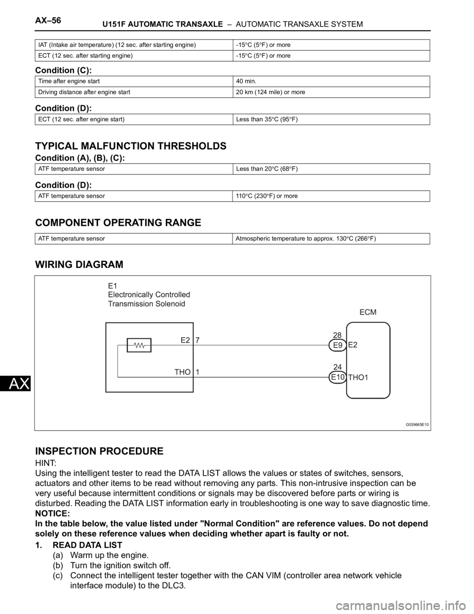
WIRING DIAGRAM
INSPECTION PROCEDURE
HINT:
Using the intelligent tester to read the DATA LIST allows the values or states of switches, sensors,
actuators and other items to be read without removing any parts. This non-intrusive inspection can be
very useful because intermittent conditions or signals may be discovered before parts or wiring is
disturbed. Reading the DATA LIST information early in troubleshooting is one way to save diagnostic time.
NOTICE:
In the table below, the value listed under "Normal Condition" are reference values. Do not depend
solely on these reference values when deciding whether apart is faulty or not.
1. READ DATA LIST
(a) Warm up the engine.
(b) Turn the ignition switch off.
(c) Connect the intelligent tester together with the CAN VIM (controller area network vehicle
interface module) to the DLC3.
IAT (Intake air temperature) (12 sec. after starting engine) -15C (5F) or more
ECT (12 sec. after starting engine) -15
C (5F) or more
Time after engine start 40 min.
Driving distance after engine start 20 km (124 mile) or more
ECT (12 sec. after engine start) Less than 35
C (95F)
ATF temperature sensor Less than 20
C (68F)
ATF temperature sensor 110
C (230F) or more
ATF temperature sensor Atmospheric temperature to approx. 130
C (266F)
G039665E10