Page 1796 of 3000
AX–124U151F AUTOMATIC TRANSAXLE – AUTOMATIC TRANSAXLE SYSTEM
AX
TYPICAL ENABLING CONDITIONS
TYPICAL MALFUNCTION THRESHOLDS
COMPONENT OPERATING RANGE
WIRING DIAGRAM
The monitor will run whenever this DTC is not present. None
Solenoid current cut status Not cut
Battery voltage11 V or more
Ignition switchON
StarterOFF
CPU commanded duty ratio to SLT 19% or more
Solenoid status from IC Fail (Open or short)
Shift solenoid valve SLT Resistance: 5.0 to 5.6
at 20C (68F)
G031770E39
Page 1800 of 3000
AX–128U151F AUTOMATIC TRANSAXLE – AUTOMATIC TRANSAXLE SYSTEM
AX
TYPICAL MALFUNCTION THRESHOLDS
P2769: Range check (Low resistance):
P2770: Range check (High resistance):
COMPONENT OPERATING RANGE
WIRING DIAGRAM
INSPECTION PROCEDURE
(a) Disconnect the transmission wire connector from the
transaxle.
(b) Measure the resistance according to the value(s) in the
table below.
Standard resistance
NG
StarterOFF
Shift solenoid valve DSL resistance 8
or less
Shift solenoid valve DSL resistance 100 k
or more
Shift solenoid valve DSL Resistance: 11 to 13
at 20C (68F)
1INSPECT TRANSMISSION WIRE (DSL)
G031165E84
C113969E11
Tester ConnectionSpecified Condition
20C (68F)
10 (DSL) - Body ground 11 to 13
Go to step 3
Page 2288 of 3000
TW–46TIRE AND WHEEL – TIRE PRESSURE WARNING SYSTEM
TW
WIRING DIAGRAM
INSPECTION PROCEDURE
NOTICE:
• When replacing the tire pressure warning ECU, read the IDs stored in the ECU using the
intelligent tester and write them down before removal.
• It is necessary to perform initialization (See page TW-23) after registration (See page TW-20) of
the transmitter IDs into the tire pressure warning ECU after the ECU and/or valve and
transmitter have been replaced.
(a) Check if the vehicle is not located in areas such as
described below:
1CHECK FREQUENCY RECEIVING CONDITION
B166325E02
Page 2305 of 3000

TIRE AND WHEEL – TIRE PRESSURE WARNING SYSTEMTW–63
TW
DESCRIPTION
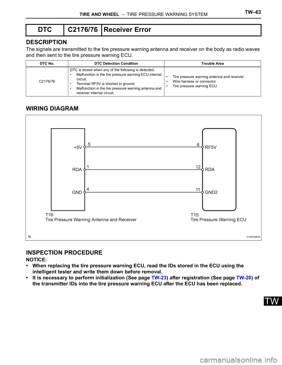
The signals are transmitted to the tire pressure warning antenna and receiver on the body as radio waves
and then sent to the tire pressure warning ECU.
WIRING DIAGRAM
INSPECTION PROCEDURE
NOTICE:
• When replacing the tire pressure warning ECU, read the IDs stored in the ECU using the
intelligent tester and write them down before removal.
• It is necessary to perform initialization (See page TW-23) after registration (See page TW-20) of
the transmitter IDs into the tire pressure warning ECU after the ECU has been replaced.
DTC C2176/76 Receiver Error
DTC No. DTC Detection Condition Trouble Area
C2176/76DTC is stored when any of the following is detected:
• Malfunction in the tire pressure warning ECU internal
circuit.
• Terminal RF5V is shorted to ground.
• Malfunction in the tire pressure warning antenna and
receiver internal circuit.• Tire pressure warning antenna and receiver
• Wire harness or connector
• Tire pressure warning ECU
C148709E08
Page 2308 of 3000
TW–66TIRE AND WHEEL – TIRE PRESSURE WARNING SYSTEM
TW
DESCRIPTION
Initialization is necessary after replacing any of the ECUs, tires with different tire pressure, or tire pressure
warning valve and transmitter, after rotating the tires or when a new vehicle is delivered.
WIRING DIAGRAM
DTC C2177/77 Initialization not Completed
DTC No. DTC Detection Condition Trouble Area
C2177/77Initialization is not completed after vehicle speed of 5
mph (8 km/h) or more continues for 20 minutes or more
(total).• Tire pressure warning valve and transmitter
• Tire pressure warning ECU
• Tire pressure warning antenna and receiver
• Wire harness or connector
B166325E03
Page 2315 of 3000

TIRE AND WHEEL – TIRE PRESSURE WARNING SYSTEMTW–73
TW
DESCRIPTION
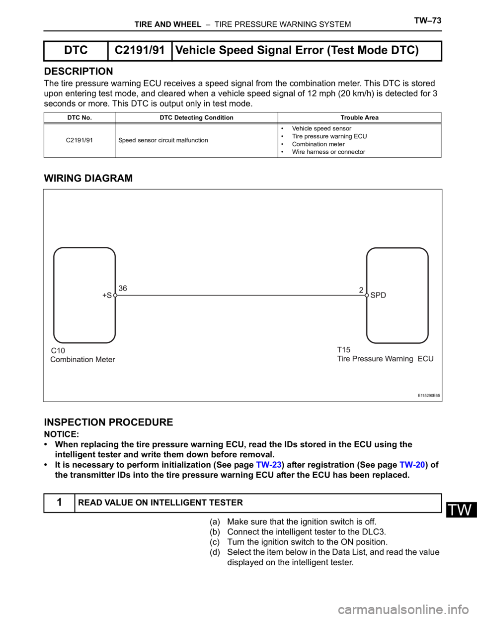
The tire pressure warning ECU receives a speed signal from the combination meter. This DTC is stored
upon entering test mode, and cleared when a vehicle speed signal of 12 mph (20 km/h) is detected for 3
seconds or more. This DTC is output only in test mode.
WIRING DIAGRAM
INSPECTION PROCEDURE
NOTICE:
• When replacing the tire pressure warning ECU, read the IDs stored in the ECU using the
intelligent tester and write them down before removal.
• It is necessary to perform initialization (See page TW-23) after registration (See page TW-20) of
the transmitter IDs into the tire pressure warning ECU after the ECU has been replaced.
(a) Make sure that the ignition switch is off.
(b) Connect the intelligent tester to the DLC3.
(c) Turn the ignition switch to the ON position.
(d) Select the item below in the Data List, and read the value
displayed on the intelligent tester.
DTC C2191/91 Vehicle Speed Signal Error (Test Mode DTC)
DTC No. DTC Detecting Condition Trouble Area
C2191/91 Speed sensor circuit malfunction• Vehicle speed sensor
• Tire pressure warning ECU
• Combination meter
• Wire harness or connector
1READ VALUE ON INTELLIGENT TESTER
E115290E65
Page 2317 of 3000
TIRE AND WHEEL – TIRE PRESSURE WARNING SYSTEMTW–75
TW
DESCRIPTION
The ECU enters the initialization mode and performs initialization automatically, when the tire pressure
warning ECU receives the signal from the tire pressure warning reset switch. If the ECU receives the
signal, the tire pressure warning light blinks 3 times (1 second on, 1 second off).
WIRING DIAGRAM
INSPECTION PROCEDURE
(a) Perform the tire pressure warning reset switch test in
TEST MODE PROCEDURE (See page TW-25).
OK:
Reset switch ON:
Tire pressure warning light comes on.
Reset switch OFF:
Tire pressure warning light blinks.
NG
OK
Tire Pressure Warning Reset Switch Circuit
1CHECK TIRE PRESSURE WARNING RESET SWITCH FUNCTION
C148712E07
Go to step 2
END
Page 2319 of 3000
TIRE AND WHEEL – TIRE PRESSURE WARNING SYSTEMTW–77
TW
DESCRIPTION
If the ECU detects trouble, the tire pressure warning light blinks (comes on after blinking for 1 minute) and
tire pressure monitor is cancelled at the same time. At this time, the ECU records a DTC in the memory.
Connect terminals TC and CG of DLC3 to make the tire pressure warning light blink and output the DTC.
WIRING DIAGRAM
INSPECTION PROCEDURE
NOTICE:
When replacing the tire pressure warning ECU, read the transmitter IDs stored in the old ECU
using the intelligent tester and write them down before removal.
It is necessary to perform initialization (See page TW-23) after registration (See page TW-20) of the
transmitter IDs into the tire pressure warning ECU, after the ECU has been replaced.
HINT:
This procedure must be performed according to the PROBLEM SYMPTOMS TABLE.
Tire Pressure Warning Light Circuit
E115290E66