Page 2488 of 3000
BC–126BRAKE CONTROL – VEHICLE STABILITY CONTROL SYSTEM
BC
WIRING DIAGRAM
INSPECTION PROCEDURE
HINT:
When U0073/94, U0100/65, U0123/62, U0124/95 or U0126/63 are output accompanied with C1232/32,
C1234/34, C1243/43, C1244/44, C1245/45 or C1381/97, inspect and repair the trouble areas indicated by
U0073/94, U0100/65, U0123/62, U0124/95 or U0126/63 first.
(a) Check that the yaw rate and deceleration sensor has
been installed properly (See page BC-197).
OK:
The sensor should be tightened to the specified
torque.
The sensor should not be tilted.
NG
OK
(a) Disconnect the yaw rate and deceleration sensor
connector.
1CHECK YAW RATE AND DECELERATION SENSOR INSTALLATION
C132917E08
INSTALL YAW RATE AND DECELERATION
SENSOR CORRECTLY
2INSPECT YAW RATE AND DECELERATION SENSOR (IG TERMINAL)
Page 2490 of 3000
BC–128BRAKE CONTROL – VEHICLE STABILITY CONTROL SYSTEM
BC
DESCRIPTION
WIRING DIAGRAM
INSPECTION PROCEDURE
(a) Remove the ECU-IG fuse from the driver side J/B.
DTC C1241/41 Low Battery Positive Voltage
DTC Code DTC Detection Condition Trouble Area
C1241/41When any of the following is detected:
1. At a vehicle speed of 3 km/h (2mph) or more, the
IG1 terminal voltage is 9.5 V or less for 10 sec. or
more.
2. When the solenoid relay remains ON and the IG1
terminal voltage is 9.5 V or less, the relay contact is
open for 0.2 sec. or more.
3. While the motor fail safe relay is ON after motor
relay ON, the IG1 terminal voltage is 9.5 V or less
and the actuator pump drive motor is OFF for 0.1
sec. or more.•Battery
• Charging system
• Power source circuit
1INSPECT ECU-IG FUSE
F045116E06
Page 2495 of 3000
BRAKE CONTROL – VEHICLE STABILITY CONTROL SYSTEMBC–133
BC
DESCRIPTION
WIRING DIAGRAM
DTC C1249/49 Open in Stop Light Switch Circuit
DTC Code DTC Detection Condition Trouble Area
C1249/49When IG1 terminal voltage is 9.5 to 18.5 V, an open
circuit of the stop light switch continues for 0.3 sec. or
more.• Stop light assembly
• Stop light switch circuit
C160967E01
Page 2500 of 3000
BC–138BRAKE CONTROL – VEHICLE STABILITY CONTROL SYSTEM
BC
DESCRIPTION
WIRING DIAGRAM
INSPECTION PROCEDURE
(a) Connect the intelligent tester to the DLC3.
(b) Start the engine.
DTC C1251/51 Open in Pump Motor Circuit
DTC Code DTC Detection Condition Trouble Area
C1251/51When either of the following is detected:
1. Actuator pump motor does not operate properly.
2. Open in actuator pump motor circuit continues for
at least 2 sec.• Brake actuator assembly (Ground circuit)
• Brake actuator assembly (Motor circuit)
1PERFORM ACTIVE TEST USING INTELLIGENT TESTER (ABS MOTOR RELAY)
F045122E02
Page 2505 of 3000
BRAKE CONTROL – VEHICLE STABILITY CONTROL SYSTEMBC–143
BC
DESCRIPTION
If any of the following is detected, the ABS warning light remains on.
• The skid control ECU connectors are disconnected from the skid control ECU.
• There is a malfunction in the skid control ECU internal circuit.
• There is an open in the harness between the combination meter and the skid control ECU.
HINT:
In some cases, the intelligent tester cannot be used when the skid control ECU is abnormal.
WIRING DIAGRAM
ABS Warning Light Remains ON
C160965E03
Page 2509 of 3000
BRAKE CONTROL – VEHICLE STABILITY CONTROL SYSTEMBC–147
BC
WIRING DIAGRAM
Refer to ABS Warning Light Remains ON (See page BC-141).
INSPECTION PROCEDURE
(a) Disconnect the skid control ECU connector.
(b) Turn the ignition switch to the ON position.
(c) Check that the ABS warning light comes on.
OK:
ABS warning light comes on.
HINT:
If troubleshooting has been carried out according to the
PROBLEM SYMPTOMS TABLE, refer back to the table
and proceed to the next step (See page BC-79).
NG
OK
(a) Turn the ignition switch off.
(b) Disconnect the combination meter connector.
ABS Warning Light does not Come ON
1CHECK ABS WARNING LIGHT
Go to step 2
REPLACE BRAKE ACTUATOR ASSEMBLY
2CHECK HARNESS AND CONNECTOR (SKID CONTROL ECU - COMBINATION METER)
Page 2511 of 3000
BRAKE CONTROL – VEHICLE STABILITY CONTROL SYSTEMBC–149
BC
DESCRIPTION
The skid control ECU is connected to the combination meter via CAN and multiplex communications.
If the skid control ECU stores DTCs to shut down TRAC and VSC operation, the VSC warning light comes
on in the combination meter.
WIRING DIAGRAM
INSPECTION PROCEDURE
NOTICE:
When replacing the brake actuator assembly, perform zero point calibration (See page BC-70).
(a) Check if the CAN communication system DTC is output
(See page CA-17).
VSC Warning Light Remains ON
1CHECK CAN COMMUNICATION SYSTEM
C160968E03
Page 2514 of 3000

BC–152BRAKE CONTROL – VEHICLE STABILITY CONTROL SYSTEM
BC
DESCRIPTION
The skid control ECU is connected to the combination meter via CAN and multiplex communications.
If the skid control ECU stores DTCs to shut down TRAC and VSC operation, the VSC warning light comes
on in the combination meter.
WIRING DIAGRAM
Refer to VSC Warning Light Remains ON (See page BC-147).
INSPECTION PROCEDURE
NOTICE:
When replacing the brake actuator assembly, perform zero point calibration (See page BC-70).
(a) Check if the CAN communication system DTC is output
(See page CA-17).
Result
B
A
(a) Check if the multiplex communication system DTC is
output (See page MP-14).
Result
B
A
(a) Connect the intelligent tester to the DLC3.
(b) Start the engine.
(c) Select the Active Test mode on the intelligent tester (See
page BC-85).
ABS / VSC:
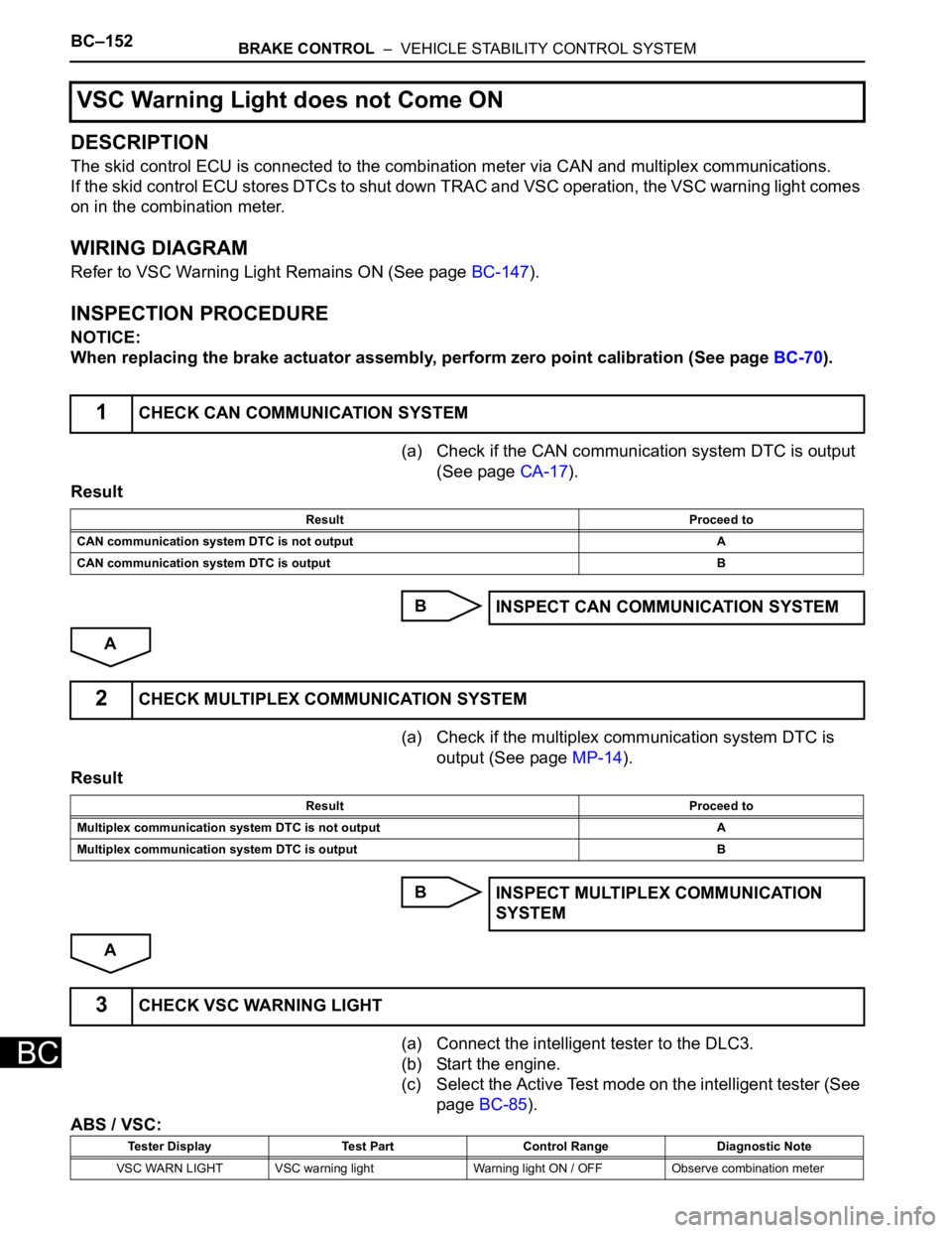
VSC Warning Light does not Come ON
1CHECK CAN COMMUNICATION SYSTEM
Result Proceed to
CAN communication system DTC is not output A
CAN communication system DTC is output B
INSPECT CAN COMMUNICATION SYSTEM
2CHECK MULTIPLEX COMMUNICATION SYSTEM
Result Proceed to
Multiplex communication system DTC is not output A
Multiplex communication system DTC is output B
INSPECT MULTIPLEX COMMUNICATION
SYSTEM
3CHECK VSC WARNING LIGHT
Tester Display Test Part Control Range Diagnostic Note
VSC WARN LIGHT VSC warning light Warning light ON / OFF Observe combination meter