Page 2818 of 3000
AIR CONDITIONING – AIR CONDITIONING SYSTEM (for Automatic Air Conditioning Sys-
tem)AC–75
AC
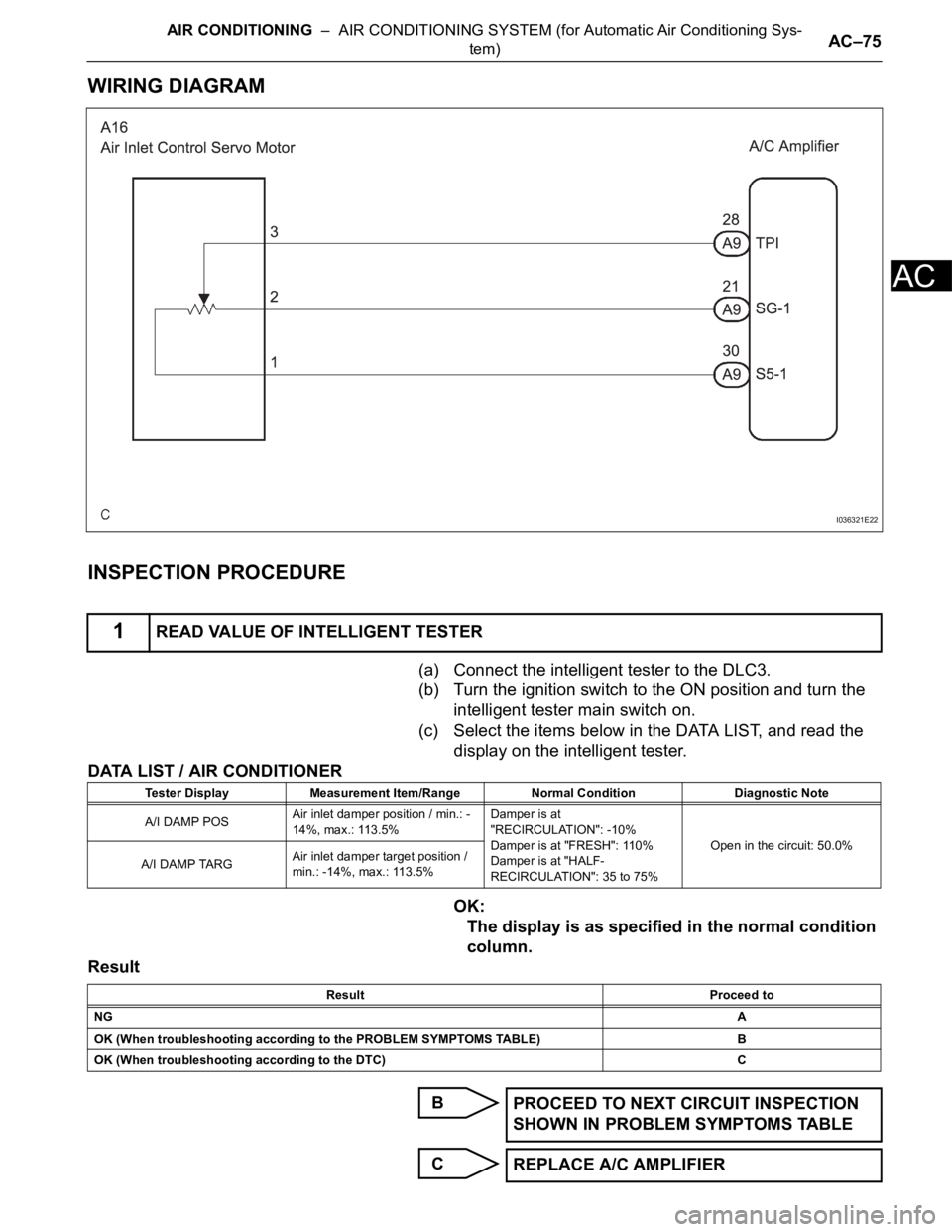
WIRING DIAGRAM
INSPECTION PROCEDURE
(a) Connect the intelligent tester to the DLC3.
(b) Turn the ignition switch to the ON position and turn the
intelligent tester main switch on.
(c) Select the items below in the DATA LIST, and read the
display on the intelligent tester.
DATA LIST / AIR CONDITIONER
OK:
The display is as specified in the normal condition
column.
Result
B
C
1READ VALUE OF INTELLIGENT TESTER
I036321E22
Tester Display Measurement Item/Range Normal Condition Diagnostic Note
A/I DAMP POSAir inlet damper position / min.: -
14%, max.: 113.5%Damper is at
"RECIRCULATION": -10%
Damper is at "FRESH": 110%
Damper is at "HALF-
RECIRCULATION": 35 to 75%Open in the circuit: 50.0%
A/I DAMP TARGAir inlet damper target position /
min.: -14%, max.: 113.5%
Result Proceed to
NGA
OK (When troubleshooting according to the PROBLEM SYMPTOMS TABLE) B
OK (When troubleshooting according to the DTC) C
PROCEED TO NEXT CIRCUIT INSPECTION
SHOWN IN PROBLEM SYMPTOMS TABLE
REPLACE A/C AMPLIFIER
Page 2822 of 3000
AIR CONDITIONING – AIR CONDITIONING SYSTEM (for Automatic Air Conditioning Sys-
tem)AC–79
AC
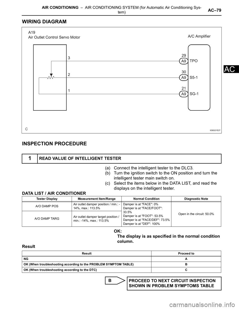
WIRING DIAGRAM
INSPECTION PROCEDURE
(a) Connect the intelligent tester to the DLC3.
(b) Turn the ignition switch to the ON position and turn the
intelligent tester main switch on.
(c) Select the items below in the DATA LIST, and read the
displays on the intelligent tester.
DATA LIST / AIR CONDITIONER
OK:
The display is as specified in the normal condition
column.
Result
B
1READ VALUE OF INTELLIGENT TESTER
I036321E27
Tester Display Measurement Item/Range Normal Condition Diagnostic Note
A/O DAMP POSAir outlet damper position / min.: -
14%, max.: 113.5%Damper is at "FACE": 0%
Damper is at "FACE/FOOT":
33.5%
Damper is at "FOOT": 53.5%
Damper is at "FACE/DEF": 73.5%
Damper is at "DEF": 100%Open in the circuit: 50.0%
A/O DAMP TARGAir outlet damper target position /
min.: -14%, max.: 113.5%
Result Proceed to
NGA
OK (When troubleshooting according to the PROBLEM SYMPTOM TABLE)B
OK (When troubleshooting according to the DTC) C
PROCEED TO NEXT CIRCUIT INSPECTION
SHOWN IN PROBLEM SYMPTOMS TABLE
Page 2826 of 3000
AIR CONDITIONING – AIR CONDITIONING SYSTEM (for Automatic Air Conditioning Sys-
tem)AC–83
AC
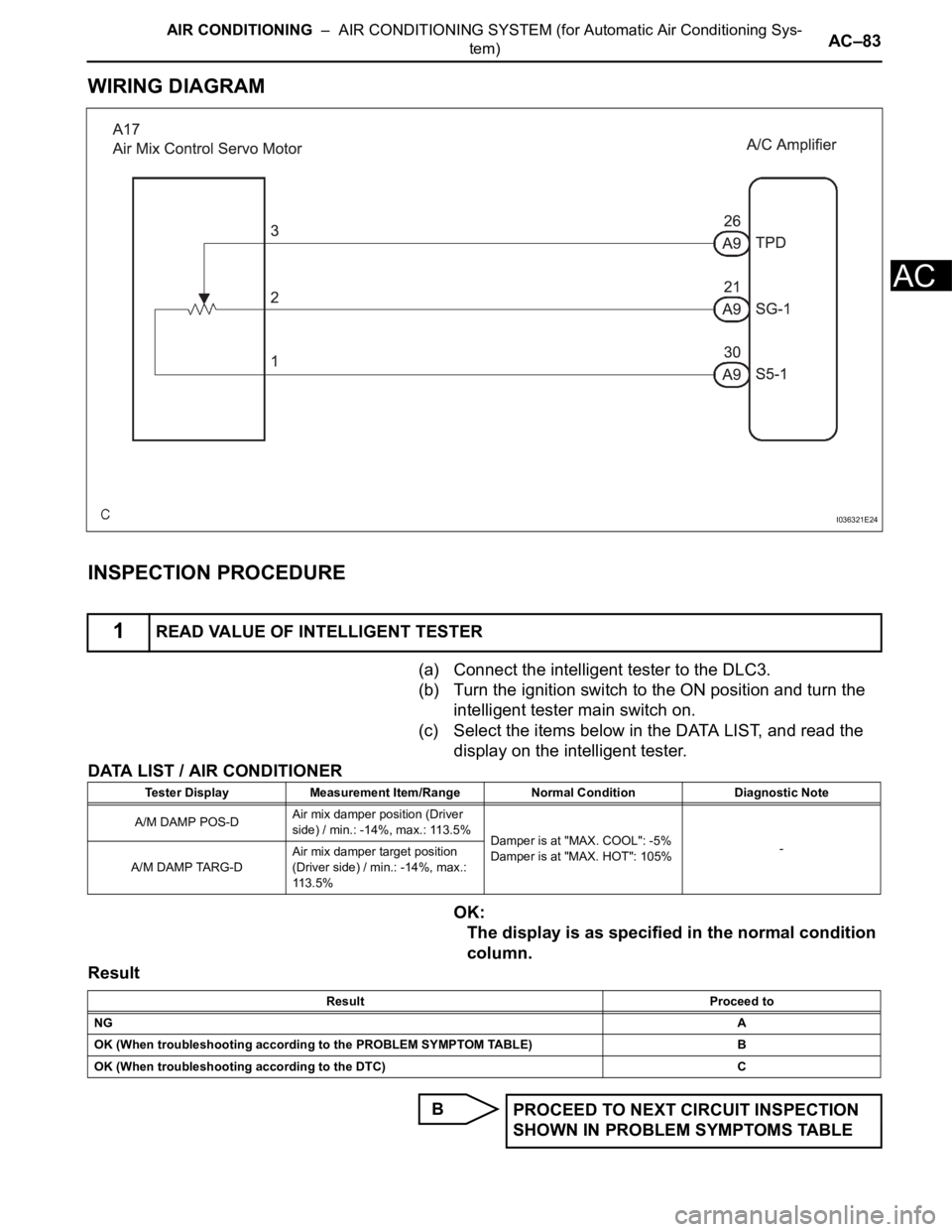
WIRING DIAGRAM
INSPECTION PROCEDURE
(a) Connect the intelligent tester to the DLC3.
(b) Turn the ignition switch to the ON position and turn the
intelligent tester main switch on.
(c) Select the items below in the DATA LIST, and read the
display on the intelligent tester.
DATA LIST / AIR CONDITIONER
OK:
The display is as specified in the normal condition
column.
Result
B
1READ VALUE OF INTELLIGENT TESTER
I036321E24
Tester Display Measurement Item/Range Normal Condition Diagnostic Note
A/M DAMP POS-DAir mix damper position (Driver
side) / min.: -14%, max.: 113.5%
Damper is at "MAX. COOL": -5%
Damper is at "MAX. HOT": 105%-
A/M DAMP TARG-DAir mix damper target position
(Driver side) / min.: -14%, max.:
11 3 . 5 %
Result Proceed to
NGA
OK (When troubleshooting according to the PROBLEM SYMPTOM TABLE)B
OK (When troubleshooting according to the DTC) C
PROCEED TO NEXT CIRCUIT INSPECTION
SHOWN IN PROBLEM SYMPTOMS TABLE
Page 2830 of 3000
AIR CONDITIONING – AIR CONDITIONING SYSTEM (for Automatic Air Conditioning Sys-
tem)AC–87
AC
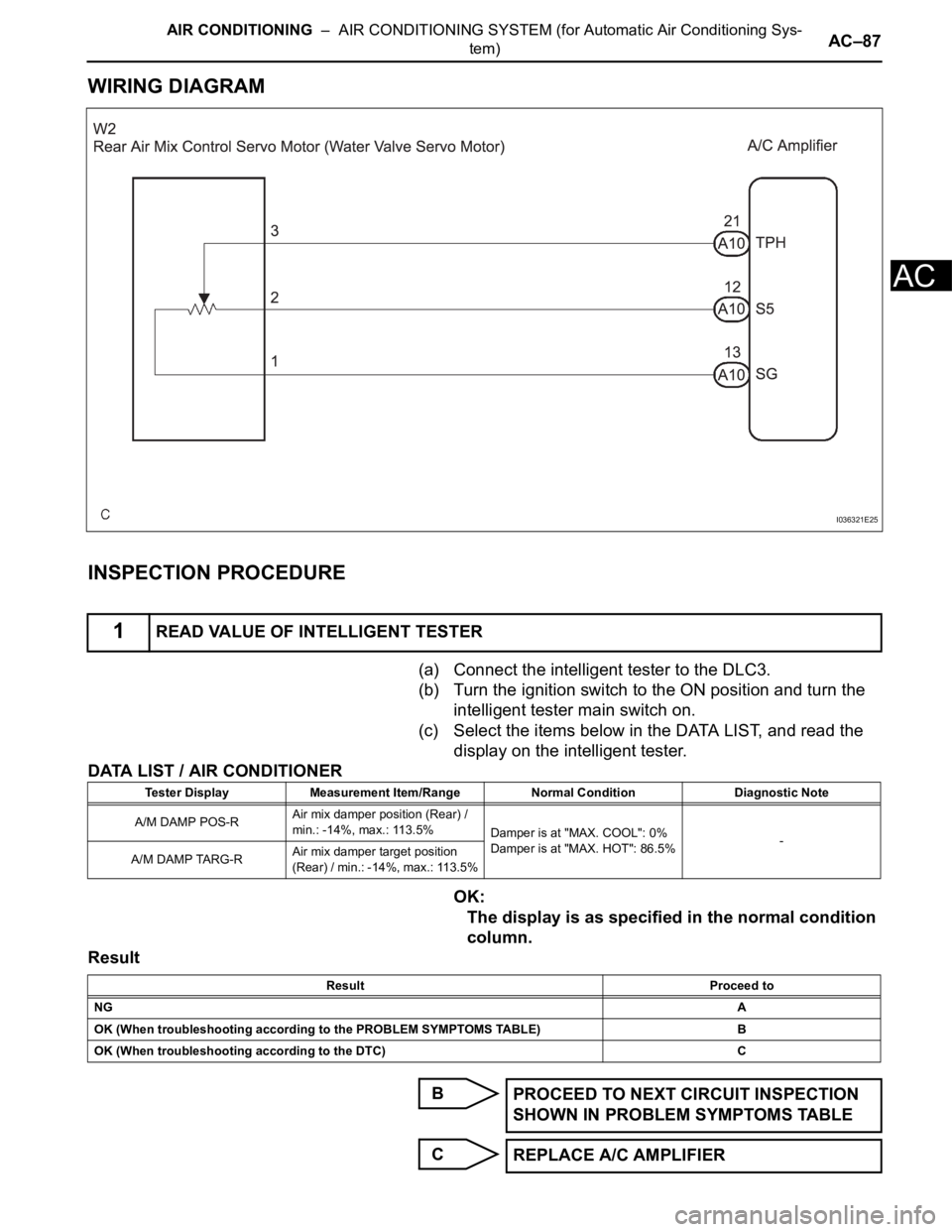
WIRING DIAGRAM
INSPECTION PROCEDURE
(a) Connect the intelligent tester to the DLC3.
(b) Turn the ignition switch to the ON position and turn the
intelligent tester main switch on.
(c) Select the items below in the DATA LIST, and read the
display on the intelligent tester.
DATA LIST / AIR CONDITIONER
OK:
The display is as specified in the normal condition
column.
Result
B
C
1READ VALUE OF INTELLIGENT TESTER
I036321E25
Tester Display Measurement Item/Range Normal Condition Diagnostic Note
A/M DAMP POS-RAir mix damper position (Rear) /
min.: -14%, max.: 113.5%
Damper is at "MAX. COOL": 0%
Damper is at "MAX. HOT": 86.5%-
A/M DAMP TARG-RAir mix damper target position
(Rear) / min.: -14%, max.: 113.5%
Result Proceed to
NGA
OK (When troubleshooting according to the PROBLEM SYMPTOMS TABLE) B
OK (When troubleshooting according to the DTC) C
PROCEED TO NEXT CIRCUIT INSPECTION
SHOWN IN PROBLEM SYMPTOMS TABLE
REPLACE A/C AMPLIFIER
Page 2834 of 3000
AIR CONDITIONING – AIR CONDITIONING SYSTEM (for Automatic Air Conditioning Sys-
tem)AC–91
AC
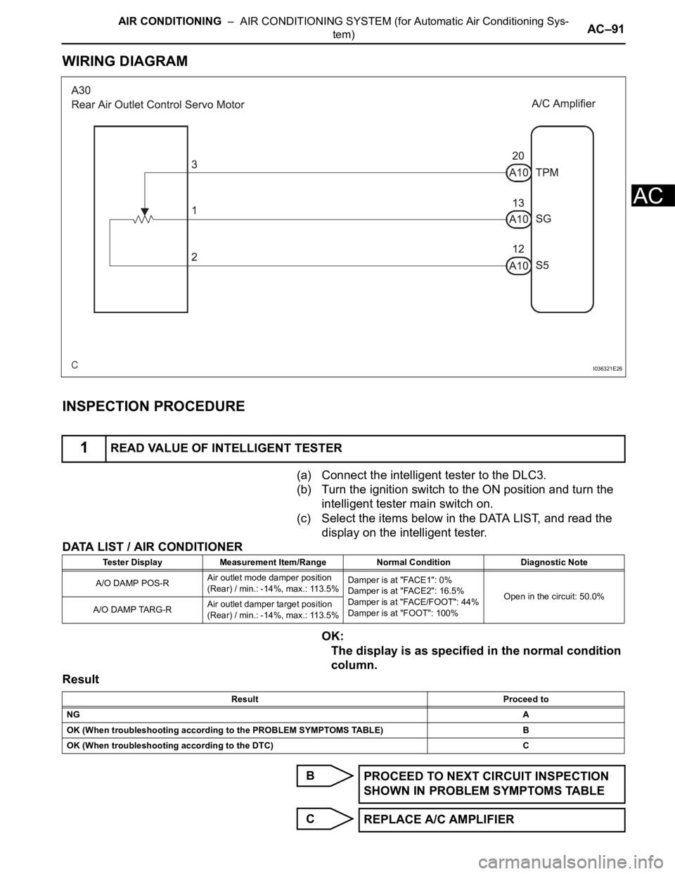
WIRING DIAGRAM
INSPECTION PROCEDURE
(a) Connect the intelligent tester to the DLC3.
(b) Turn the ignition switch to the ON position and turn the
intelligent tester main switch on.
(c) Select the items below in the DATA LIST, and read the
display on the intelligent tester.
DATA LIST / AIR CONDITIONER
OK:
The display is as specified in the normal condition
column.
Result
B
C
1READ VALUE OF INTELLIGENT TESTER
I036321E26
Tester Display Measurement Item/Range Normal Condition Diagnostic Note
A/O DAMP POS-RAir outlet mode damper position
(Rear) / min.: -14%, max.: 113.5%Damper is at "FACE1": 0%
Damper is at "FACE2": 16.5%
Damper is at "FACE/FOOT": 44%
Damper is at "FOOT": 100%Open in the circuit: 50.0%
A/O DAMP TARG-RAir outlet damper target position
(Rear) / min.: -14%, max.: 113.5%
Result Proceed to
NGA
OK (When troubleshooting according to the PROBLEM SYMPTOMS TABLE) B
OK (When troubleshooting according to the DTC) C
PROCEED TO NEXT CIRCUIT INSPECTION
SHOWN IN PROBLEM SYMPTOMS TABLE
REPLACE A/C AMPLIFIER
Page 2837 of 3000
AC–94AIR CONDITIONING – AIR CONDITIONING SYSTEM (for Automatic Air Conditioning Sys-
tem)
AC
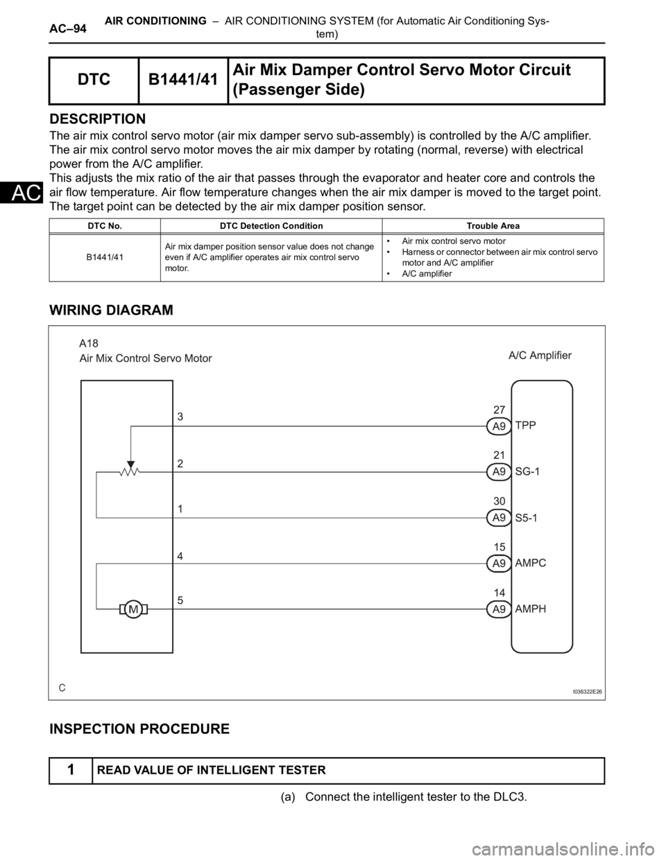
DESCRIPTION
The air mix control servo motor (air mix damper servo sub-assembly) is controlled by the A/C amplifier.
The air mix control servo motor moves the air mix damper by rotating (normal, reverse) with electrical
power from the A/C amplifier.
This adjusts the mix ratio of the air that passes through the evaporator and heater core and controls the
air flow temperature. Air flow temperature changes when the air mix damper is moved to the target point.
The target point can be detected by the air mix damper position sensor.
WIRING DIAGRAM
INSPECTION PROCEDURE
(a) Connect the intelligent tester to the DLC3.
DTC B1441/41Air Mix Damper Control Servo Motor Circuit
(Passenger Side)
DTC No. DTC Detection Condition Trouble Area
B1441/41Air mix damper position sensor value does not change
even if A/C amplifier operates air mix control servo
motor.• Air mix control servo motor
• Harness or connector between air mix control servo
motor and A/C amplifier
• A/C amplifier
1READ VALUE OF INTELLIGENT TESTER
I036322E26
Page 2842 of 3000
AIR CONDITIONING – AIR CONDITIONING SYSTEM (for Automatic Air Conditioning Sys-
tem)AC–99
AC
DESCRIPTION
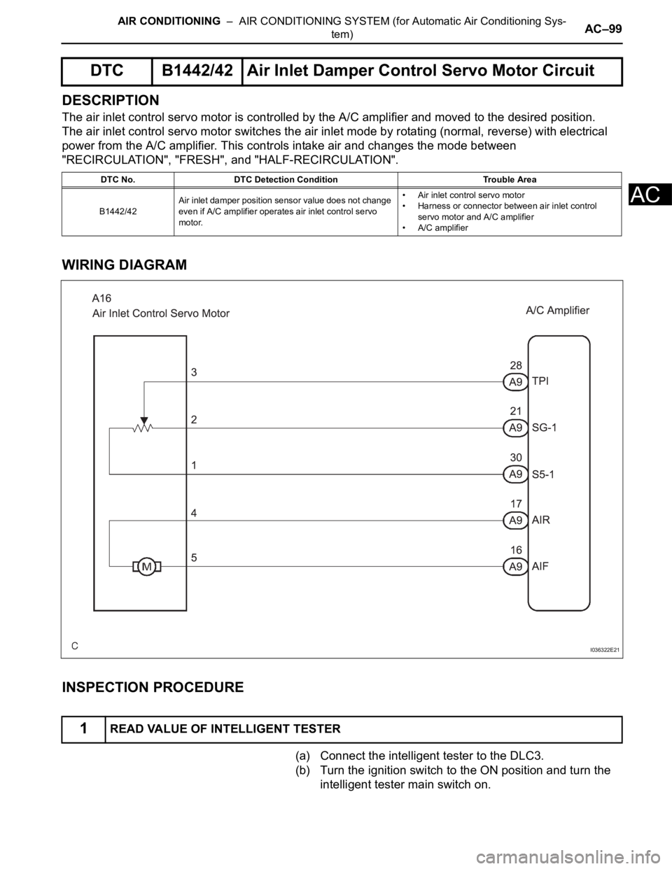
The air inlet control servo motor is controlled by the A/C amplifier and moved to the desired position.
The air inlet control servo motor switches the air inlet mode by rotating (normal, reverse) with electrical
power from the A/C amplifier. This controls intake air and changes the mode between
"RECIRCULATION", "FRESH", and "HALF-RECIRCULATION".
WIRING DIAGRAM
INSPECTION PROCEDURE
(a) Connect the intelligent tester to the DLC3.
(b) Turn the ignition switch to the ON position and turn the
intelligent tester main switch on.
DTC B1442/42 Air Inlet Damper Control Servo Motor Circuit
DTC No. DTC Detection Condition Trouble Area
B1442/42Air inlet damper position sensor value does not change
even if A/C amplifier operates air inlet control servo
motor.• Air inlet control servo motor
• Harness or connector between air inlet control
servo motor and A/C amplifier
• A/C amplifier
1READ VALUE OF INTELLIGENT TESTER
I036322E21
Page 2847 of 3000
AC–104AIR CONDITIONING – AIR CONDITIONING SYSTEM (for Automatic Air Conditioning Sys-
tem)
AC
DESCRIPTION
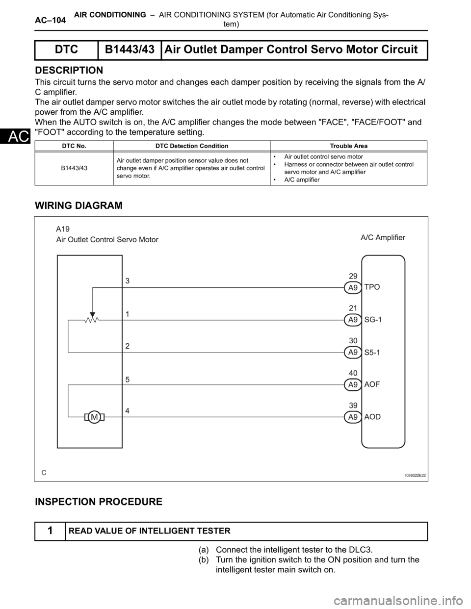
This circuit turns the servo motor and changes each damper position by receiving the signals from the A/
C amplifier.
The air outlet damper servo motor switches the air outlet mode by rotating (normal, reverse) with electrical
power from the A/C amplifier.
When the AUTO switch is on, the A/C amplifier changes the mode between "FACE", "FACE/FOOT" and
"FOOT" according to the temperature setting.
WIRING DIAGRAM
INSPECTION PROCEDURE
(a) Connect the intelligent tester to the DLC3.
(b) Turn the ignition switch to the ON position and turn the
intelligent tester main switch on.
DTC B1443/43 Air Outlet Damper Control Servo Motor Circuit
DTC No. DTC Detection Condition Trouble Area
B1443/43Air outlet damper position sensor value does not
change even if A/C amplifier operates air outlet control
servo motor.• Air outlet control servo motor
• Harness or connector between air outlet control
servo motor and A/C amplifier
• A/C amplifier
1READ VALUE OF INTELLIGENT TESTER
I036322E22