Page 2888 of 3000

AIR CONDITIONING – AIR CONDITIONING SYSTEM (for Automatic Air Conditioning Sys-
tem)AC–145
AC
DESCRIPTION
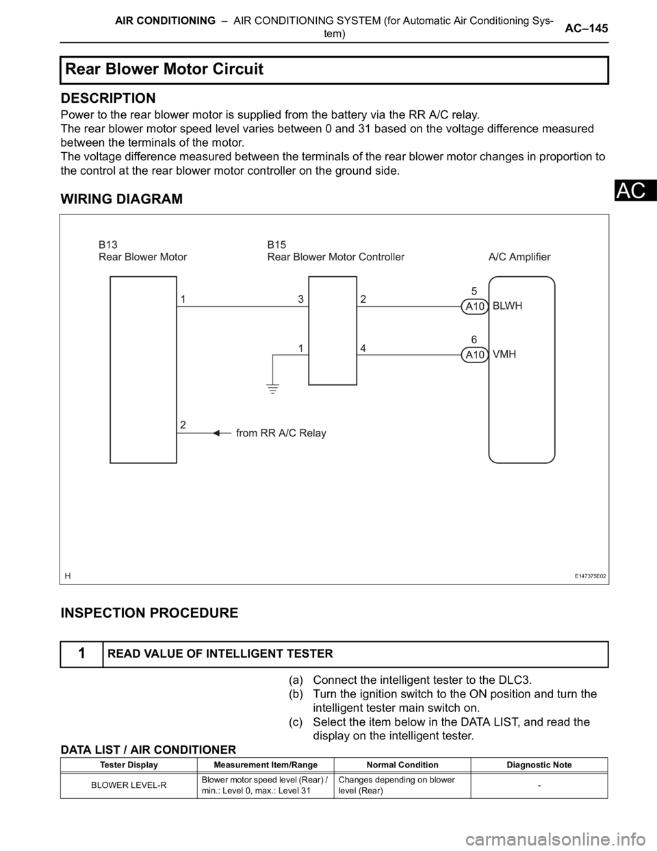
Power to the rear blower motor is supplied from the battery via the RR A/C relay.
The rear blower motor speed level varies between 0 and 31 based on the voltage difference measured
between the terminals of the motor.
The voltage difference measured between the terminals of the rear blower motor changes in proportion to
the control at the rear blower motor controller on the ground side.
WIRING DIAGRAM
INSPECTION PROCEDURE
(a) Connect the intelligent tester to the DLC3.
(b) Turn the ignition switch to the ON position and turn the
intelligent tester main switch on.
(c) Select the item below in the DATA LIST, and read the
display on the intelligent tester.
DATA LIST / AIR CONDITIONER
Rear Blower Motor Circuit
1READ VALUE OF INTELLIGENT TESTER
E147375E02
Tester Display Measurement Item/Range Normal Condition Diagnostic Note
BLOWER LEVEL-RBlower motor speed level (Rear) /
min.: Level 0, max.: Level 31Changes depending on blower
level (Rear)-
Page 2893 of 3000
AC–150AIR CONDITIONING – AIR CONDITIONING SYSTEM (for Automatic Air Conditioning Sys-
tem)
AC
DESCRIPTION
The main power source is supplied to the A/C amplifier when the ignition switch is turned to the ON
position.
The power source is used for operating the A/C amplifier and servo motor, etc.
WIRING DIAGRAM
INSPECTION PROCEDURE
HINT:
Start the engine before inspection. Check the IG1 relay or battery if the engine does not start.
(a) Remove the HTR fuse from the driver side junction
block.
(b) Measure the resistance according to the value(s) in the
table below.
Standard resistance
NG
IG Power Source Circuit
1INSPECT FUSE (HTR)
E130466E04
Tester Item Condition Specified Condition
HTR fuse Always Below 1
REPLACE FUSE (HTR)
Page 2896 of 3000
AIR CONDITIONING – AIR CONDITIONING SYSTEM (for Automatic Air Conditioning Sys-
tem)AC–153
AC
DESCRIPTION
This circuit supplies power to the A/C amplifier and the illumination for the clock.
WIRING DIAGRAM
INSPECTION PROCEDURE
(a) Remove the ECU ACC fuse from the engine room relay
block.
(b) Measure the resistance according to the value(s) in the
table below.
Standard resistance
NG
OK
ACC Power Source Circuit
1INSPECT FUSE (ECU ACC)
E146556E02
Tester Item Condition Specified Condition
ECU ACC Fuse Always Below 1
REPLACE FUSE (ECU ACC)
Page 2898 of 3000
AIR CONDITIONING – AIR CONDITIONING SYSTEM (for Automatic Air Conditioning Sys-
tem)AC–155
AC
DESCRIPTION
This is the back-up power source for the A/C amplifier. Power is supplied even when the ignition switch is
off and is used for diagnostic trouble code memory, etc.
WIRING DIAGRAM
INSPECTION PROCEDURE
(a) Remove the ECU-B fuse from the engine room junction
block.
(b) Measure the resistance according to the value(s) in the
table below.
Standard resistance
NG
OK
Back-up Power Source Circuit
1INSPECT FUSE (ECU-B)
E146556E03
Tester Item Condition Specified Condition
ECU-B Fuse Always Below 1
REPLACE FUSE (ECU-B)
Page 2934 of 3000
AC–26AIR CONDITIONING – AIR CONDITIONING SYSTEM (for Automatic Air Conditioning Sys-
tem)
AC
DESCRIPTION
This sensor detects the cabin temperature that is used as the basis for temperature control and sends a
signal to the A/C amplifier.
WIRING DIAGRAM
INSPECTION PROCEDURE
(a) Connect the intelligent tester to the DLC3.
(b) Turn the ignition switch to the ON position and turn the
intelligent tester main switch on.
DTC B1411/11 Room Temperature Sensor Circuit
DTC No. DTC Detection Condition Trouble Area
B1411/11 Room temperature sensor circuit (Open or short)• A/C room temperature sensor
• Harness or connector between A/C room
temperature sensor and A/C amplifier
• A/C amplifier
1READ VALUE OF INTELLIGENT TESTER
I008282E16
Page 2937 of 3000

AIR CONDITIONING – AIR CONDITIONING SYSTEM (for Automatic Air Conditioning Sys-
tem)AC–29
AC
DESCRIPTION
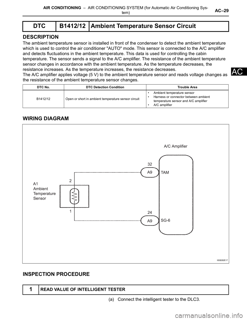
The ambient temperature sensor is installed in front of the condenser to detect the ambient temperature
which is used to control the air conditioner "AUTO" mode. This sensor is connected to the A/C amplifier
and detects fluctuations in the ambient temperature. This data is used for controlling the cabin
temperature. The sensor sends a signal to the A/C amplifier. The resistance of the ambient temperature
sensor changes in accordance with the ambient temperature. As the temperature decreases, the
resistance increases. As the temperature increases, the resistance decreases.
The A/C amplifier applies voltage (5 V) to the ambient temperature sensor and reads voltage changes as
the resistance of the ambient temperature sensor changes.
WIRING DIAGRAM
INSPECTION PROCEDURE
(a) Connect the intelligent tester to the DLC3.
DTC B1412/12 Ambient Temperature Sensor Circuit
DTC No. DTC Detection Condition Trouble Area
B1412/12 Open or short in ambient temperature sensor circuit• Ambient temperature sensor
• Harness or connector between ambient
temperature sensor and A/C amplifier
• A/C amplifier
1READ VALUE OF INTELLIGENT TESTER
I008282E17
Page 2946 of 3000

AIR CONDITIONING – AIR CONDITIONING SYSTEM (for Automatic Air Conditioning Sys-
tem)AC–33
AC
DESCRIPTION
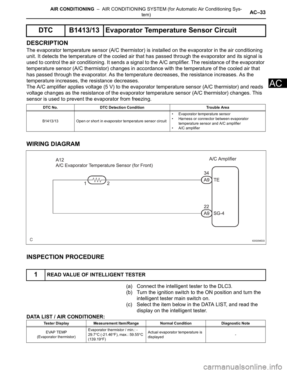
The evaporator temperature sensor (A/C thermistor) is installed on the evaporator in the air conditioning
unit. It detects the temperature of the cooled air that has passed through the evaporator and its signal is
used to control the air conditioning. It sends a signal to the A/C amplifier. The resistance of the evaporator
temperature sensor (A/C thermistor) changes in accordance with the temperature of the cooled air that
has passed through the evaporator. As the temperature decreases, the resistance increases. As the
temperature increases, the resistance decreases.
The A/C amplifier applies voltage (5 V) to the evaporator temperature sensor (A/C thermistor) and reads
voltage changes as the resistance of the evaporator temperature sensor (A/C thermistor) changes. This
sensor is used to prevent the evaporator from freezing.
WIRING DIAGRAM
INSPECTION PROCEDURE
(a) Connect the intelligent tester to the DLC3.
(b) Turn the ignition switch to the ON position and turn the
intelligent tester main switch on.
(c) Select the item below in the DATA LIST, and read the
display on the intelligent tester.
DATA LIST / AIR CONDITIONER:
DTC B1413/13 Evaporator Temperature Sensor Circuit
DTC No. DTC Detection Condition Trouble Area
B1413/13 Open or short in evaporator temperature sensor circuit• Evaporator temperature sensor
• Harness or connector between evaporator
temperature sensor and A/C amplifier
• A/C amplifier
1READ VALUE OF INTELLIGENT TESTER
I035354E03
Tester Display Measurement Item/Range Normal Condition Diagnostic Note
EVAP TEMP
(Evaporator thermistor)Evaporator thermistor / min.: -
29.7
C (-21.46F), max.: 59.55C
(139.19F)Actual evaporator temperature is
displayed-
Page 2950 of 3000

AC–36AIR CONDITIONING – AIR CONDITIONING SYSTEM (for Automatic Air Conditioning Sys-
tem)
AC
DESCRIPTION
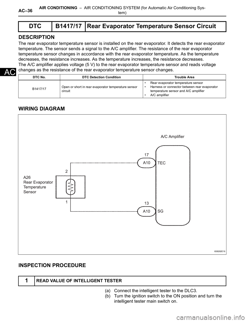
The rear evaporator temperature sensor is installed on the rear evaporator. It detects the rear evaporator
temperature. The sensor sends a signal to the A/C amplifier. The resistance of the rear evaporator
temperature sensor changes in accordance with the rear evaporator temperature. As the temperature
decreases, the resistance increases. As the temperature increases, the resistance decreases.
The A/C amplifier applies voltage (5 V) to the rear evaporator temperature sensor and reads voltage
changes as the resistance of the rear evaporator temperature sensor changes.
WIRING DIAGRAM
INSPECTION PROCEDURE
(a) Connect the intelligent tester to the DLC3.
(b) Turn the ignition switch to the ON position and turn the
intelligent tester main switch on.
DTC B1417/17 Rear Evaporator Temperature Sensor Circuit
DTC No. DTC Detection Condition Trouble Area
B1417/17Open or short in rear evaporator temperature sensor
circuit• Rear evaporator temperature sensor
• Harness or connector between rear evaporator
temperature sensor and A/C amplifier
• A/C amplifier
1READ VALUE OF INTELLIGENT TESTER
I008282E19