Page 2404 of 3000
BRAKE CONTROL – ANTI-LOCK BRAKE SYSTEMBC–43
BC
DESCRIPTION
This skid control ECU inputs the stop light switch signal and detects the status of brake operation.
The skid control ECU has an open detection circuit. If an open in the stop light switch input line or GND
side stop light circuit is detected when the stop light switch is off, this DTC is output.
WIRING DIAGRAM
DTC C1249/49 Open in Stop Light Switch Circuit
DTC No. DTC Detection Condition Trouble Area
C1249/49With the IG1 terminal voltage at 10 V to 16 V, ABS is not
operating and stop light switch circuit is open for 1
second or more.• Stop light switch
• Stop light switch circuit
C160964E01
Page 2408 of 3000

BRAKE CONTROL – ANTI-LOCK BRAKE SYSTEMBC–47
BC
DESCRIPTION
The motor relay (semiconductor relay) is housed in the brake actuator assembly and drives the pump
motor based on a signal from the skid control ECU.
WIRING DIAGRAM
Refer to DTCs C0273/13 and C0274/14 (See page BC-31).
INSPECTION PROCEDURE
HINT:
After step 1 is complete, start the inspection from step 2 when using the intelligent tester, and from step 3
when not using the intelligent tester.
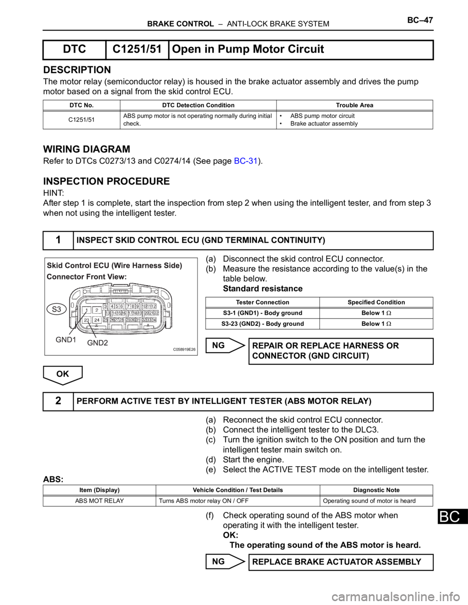
(a) Disconnect the skid control ECU connector.
(b) Measure the resistance according to the value(s) in the
table below.
Standard resistance
NG
OK
(a) Reconnect the skid control ECU connector.
(b) Connect the intelligent tester to the DLC3.
(c) Turn the ignition switch to the ON position and turn the
intelligent tester main switch on.
(d) Start the engine.
(e) Select the ACTIVE TEST mode on the intelligent tester.
ABS:
(f) Check operating sound of the ABS motor when
operating it with the intelligent tester.
OK:
The operating sound of the ABS motor is heard.
NG
DTC C1251/51 Open in Pump Motor Circuit
DTC No. DTC Detection Condition Trouble Area
C1251/51ABS pump motor is not operating normally during initial
check.• ABS pump motor circuit
• Brake actuator assembly
1INSPECT SKID CONTROL ECU (GND TERMINAL CONTINUITY)
C058919E26
Tester Connection Specified Condition
S3-1 (GND1) - Body ground Below 1
S3-23 (GND2) - Body ground Below 1
REPAIR OR REPLACE HARNESS OR
CONNECTOR (GND CIRCUIT)
2PERFORM ACTIVE TEST BY INTELLIGENT TESTER (ABS MOTOR RELAY)
Item (Display) Vehicle Condition / Test Details Diagnostic Note
ABS MOT RELAY Turns ABS motor relay ON / OFF Operating sound of motor is heard
REPLACE BRAKE ACTUATOR ASSEMBLY
Page 2410 of 3000
BRAKE CONTROL – ANTI-LOCK BRAKE SYSTEMBC–49
BC
DESCRIPTION
If any of the following is detected, the ABS warning light remains on.
• The skid control ECU connectors are disconnected from the skid control ECU.
• There is a malfunction in the skid control ECU internal circuit.
• There is an open in the harness between the combination meter and the skid control ECU.
HINT:
In some cases, the intelligent tester cannot be used when the skid control ECU is abnormal.
WIRING DIAGRAM
ABS Warning Light Remains ON
C160965E01
Page 2413 of 3000
BC–52BRAKE CONTROL – ANTI-LOCK BRAKE SYSTEM
BC
WIRING DIAGRAM
See page BC-47.
INSPECTION PROCEDURE
(a) Disconnect the skid control ECU connector.
(b) Turn the ignition switch to the ON position.
(c) Check that the ABS warning light comes on.
OK:
ABS warning light comes on.
HINT:
If troubleshooting has been carried out according to the
PROBLEM SYMPTOMS TABLE, refer back to the table
and proceed to the next step (See page BC-7).
NG
OK
ABS Warning Light does not Come ON
1INSPECT ABS WARNING LIGHT
Go to step 2
REPLACE BRAKE ACTUATOR ASSEMBLY
Page 2415 of 3000
BC–54BRAKE CONTROL – ANTI-LOCK BRAKE SYSTEM
BC
DESCRIPTION
If the ECU detects a trouble, it turns on the brake warning light at the same time of prohibiting ABS
control.
At this time, the ECU records a DTC in memory.
Connect terminals TC and CG of the DLC3 to make the brake warning light blink and output the DTC.
WIRING DIAGRAM
Brake Warning Light Remains ON
C160966E01
Page 2422 of 3000
BRAKE CONTROL – ANTI-LOCK BRAKE SYSTEMBC–61
BC
WIRING DIAGRAM
See page BC-52.
INSPECTION PROCEDURE
(a) Disconnect the skid control ECU connector.
(b) Turn the ignition switch to the on position.
(c) Check that the BRAKE warning light comes on.
OK:
BRAKE warning light comes on.
HINT:
If troubleshooting has been carried out according to the
PROBLEM SYMPTOMS TABLE, refer back to the table and
proceed to the next step before replacing the part (See page
BC-7).
NG
OK
(a) Turn the ignition switch off.
(b) Disconnect the combination meter connector.
Brake Warning Light does not Come ON
1INSPECT BRAKE WARNING LIGHT
Go to step 2
REPLACE BRAKE ACTUATOR ASSEMBLY
2CHECK HARNESS AND CONNECTOR (BETWEEN SKID CONTROL ECU AND
COMBINATION METER ASSEMBLY)
Page 2424 of 3000
BRAKE CONTROL – ANTI-LOCK BRAKE SYSTEMBC–63
BC
DESCRIPTION
DTC output mode is set by connecting terminals TC and CG of the DLC3.
The DTCs are displayed by the blinking pattern of the ABS warning light.
WIRING DIAGRAM
HINT:
When warning lights continue to blink, a ground short in the wiring of terminal TC of the DLC3 or an
internal ground short in one or more ECU is suspected.
INSPECTION PROCEDURE
(a) Turn the ignition switch to the ON position.
(b) Measure the voltage according to the value(s) in the
table below.
Standard voltage
NG
OK
TC and CG Terminal Circuit
1INSPECT DLC3 (BETWEEN TC of DLC3 AND CG of DLC3)
C114571E09
E106867E21
Tester Connection Specified Condition
D1-13 (TC) - D1-4 (CG) 10 to 14 V
Go to step 3
Page 2427 of 3000
BC–66BRAKE CONTROL – ANTI-LOCK BRAKE SYSTEM
BC
DESCRIPTION
The Test Mode (signal check) circuit detects trouble in the sensor or switch signal, which cannot be
detected by the DTC check.
Connecting terminals TS and CG of the DLC3 starts the check.
WIRING DIAGRAM
TS and CG Terminal Circuit
C114571E10