Page 2457 of 3000
BRAKE CONTROL – VEHICLE STABILITY CONTROL SYSTEMBC–95
BC
WIRING DIAGRAM
INSPECTION PROCEDURE
(a) Connect the intelligent tester to the DLC3.
(b) Start the engine.
(c) Select the DATA LIST mode on the intelligent tester.
ABS / VSC:
(d) Check that there is no difference between the speed
value output from the speed sensor displayed on the
intelligent tester and the speed value displayed on the
speedometer when driving the vehicle.
OK:
There is almost no difference from the displayed
speed value.
HINT:
There is tolerance of +- 10 % in the speedometer
indication.
NG
OK
1READ VALUE ON INTELLIGENT TESTER (FRONT SPEED SENSOR)
F040884E11
Tester Display Measurement Item/Range Normal Condition
WHEEL SPD FRWheel speed sensor (FR) reading / min.: 0
km/h (0 MPH), max.: 326 km/h (202 MPH)Actual wheel speed
WHEEL SPD FLWheel speed sensor (FL) reading / min.: 0
km/h (0 MPH), max.: 326 km/h (202 MPH)Actual wheel speed
Go to step 3
Page 2462 of 3000
BC–100BRAKE CONTROL – VEHICLE STABILITY CONTROL SYSTEM
BC
DESCRIPTION
Refer to DTCs C0200/31, C0205/32, C1235/35 and C1236/36 (See page BC-92).
HINT:
• DTC C0210/33 and C1238/38 are for the right rear speed sensor.
• DTC C0215/34 and C1239/39 are for the left rear speed sensor.
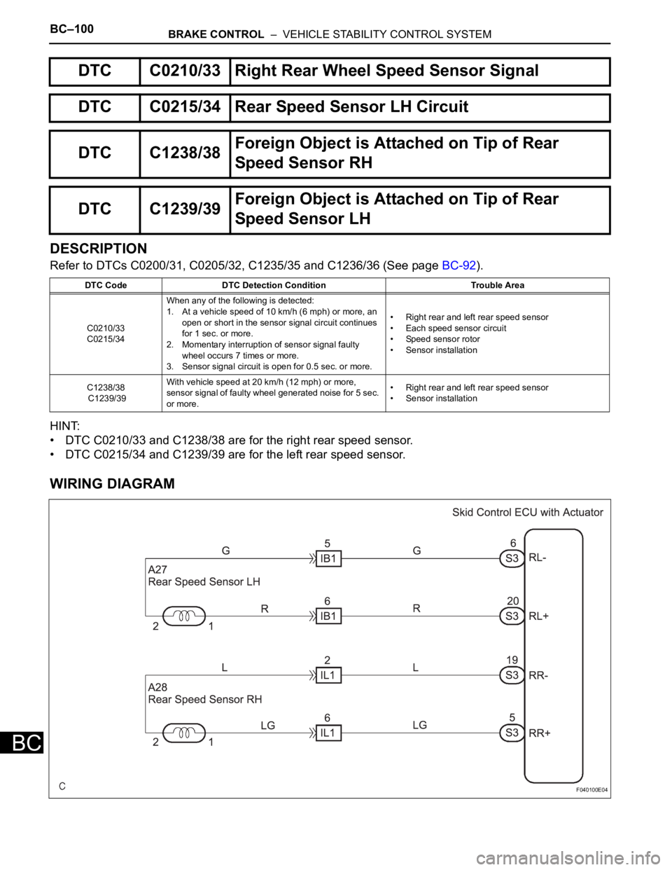
WIRING DIAGRAM
DTC C0210/33 Right Rear Wheel Speed Sensor Signal
DTC C0215/34 Rear Speed Sensor LH Circuit
DTC C1238/38Foreign Object is Attached on Tip of Rear
Speed Sensor RH
DTC C1239/39Foreign Object is Attached on Tip of Rear
Speed Sensor LH
DTC Code DTC Detection Condition Trouble Area
C0210/33
C0215/34When any of the following is detected:
1. At a vehicle speed of 10 km/h (6 mph) or more, an
open or short in the sensor signal circuit continues
for 1 sec. or more.
2. Momentary interruption of sensor signal faulty
wheel occurs 7 times or more.
3. Sensor signal circuit is open for 0.5 sec. or more.• Right rear and left rear speed sensor
• Each speed sensor circuit
• Speed sensor rotor
• Sensor installation
C1238/38
C1239/39With vehicle speed at 20 km/h (12 mph) or more,
sensor signal of faulty wheel generated noise for 5 sec.
or more. • Right rear and left rear speed sensor
• Sensor installation
F040100E04
Page 2469 of 3000
BRAKE CONTROL – VEHICLE STABILITY CONTROL SYSTEMBC–107
BC
DESCRIPTION
This solenoid goes on when signals are received from the ECU and controls the pressure acting on the
wheel cylinders to control the braking force.
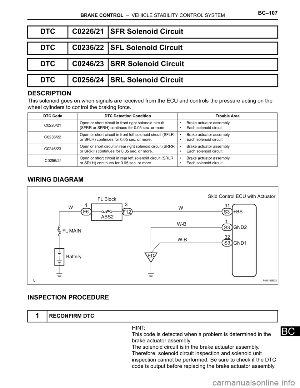
WIRING DIAGRAM
INSPECTION PROCEDURE
HINT:
This code is detected when a problem is determined in the
brake actuator assembly.
The solenoid circuit is in the brake actuator assembly.
Therefore, solenoid circuit inspection and solenoid unit
inspection cannot be performed. Be sure to check if the DTC
code is output before replacing the brake actuator assembly.
DTC C0226/21 SFR Solenoid Circuit
DTC C0236/22 SFL Solenoid Circuit
DTC C0246/23 SRR Solenoid Circuit
DTC C0256/24 SRL Solenoid Circuit
DTC Code DTC Detection Condition Trouble Area
C0226/21Open or short circuit in front right solenoid circuit
(SFRR or SFRH) continues for 0.05 sec. or more.• Brake actuator assembly
• Each solenoid circuit
C0236/22Open or short circuit in front left solenoid circuit (SFLR
or SFLH) continues for 0.05 sec. or more.• Brake actuator assembly
• Each solenoid circuit
C0246/23Open or short circuit in rear right solenoid circuit (SRRR
or SRRH) continues for 0.05 sec. or more.• Brake actuator assembly
• Each solenoid circuit
C0256/24Open or short circuit in rear left solenoid circuit (SRLR
or SRLH) continues for 0.05 sec. or more.• Brake actuator assembly
• Each solenoid circuit
1RECONFIRM DTC
F045115E02
Page 2472 of 3000
BC–110BRAKE CONTROL – VEHICLE STABILITY CONTROL SYSTEM
BC
WIRING DIAGRAM
INSPECTION PROCEDURE
(a) Connect the intelligent tester to the DLC3.
(b) Start the engine.
(c) Select the ACTIVE TEST mode on the intelligent tester.
ABS / VSC:
(d) Check the operation sound of the ABS motor individually
when operating it with the intelligent tester.
OK:
Operation sound of the ABS motor should be
heard.
NG
1PERFORM ACTIVE TEST USING INTELLIGENT TESTER (ABS MOTOR RELAY)
F045122E04
Tester Display Test Part Control Range Diagnostic Note
ABS MOT RELAY ABS motor relay Relay ON / OFFOperation of motor (clicking
sound) can be heard
Go to step 2
Page 2476 of 3000
BC–114BRAKE CONTROL – VEHICLE STABILITY CONTROL SYSTEM
BC
DESCRIPTION
The ABS solenoid relay is built in the brake actuator assembly. This relay supplies power to each ABS
solenoid. If the initial check is OK, after the ignition switch is turned to the ON position, the relay goes on.
WIRING DIAGRAM
Refer to DTCs C0226/21, C0236/22, C0246/23 and C0256/24 (See page BC-105).
INSPECTION PROCEDURE
(a) Remove the ABS 2 fuse from the FL block.
(b) Measure the resistance according to the value(s) in the
table below.
Standard resistance
NG
OK
(a) Disconnect the skid control ECU connector.
(b) Turn the ignition switch to the ON position.
DTC C0278/11Open or Short Circuit in ABS Solenoid Relay
Circuit
DTC C0279/12 Short to B+ in ABS Solenoid Relay Circuit
DTC Code DTC Detection Condition Trouble Area
C0278/11When either of the following is detected:
1. Both of the following conditions continue for 0.2
sec. or more.
– The IG1 terminal voltage is between 9.5 and
18.5 V.
– The solenoid relay contact is open when the
relay is turned on.
2. Both of the following conditions continue for 0.2
sec. or more.
– IG1 terminal voltage becomes lower than 9.5 V
or less when the relay is turned on.
– The relay contact remains open.• ABS 2 fuse
• ABS SOL relay
• ABS SOL relay circuit
• Brake actuator assembly
C0279/12Immediately after IG1 is turned ON, when solenoid
relay is turned OFF, relay contact is "ON" for 0.2 sec. or
more.• ABS 2 fuse
• ABS SOL relay
• ABS SOL relay circuit
• Brake actuator assembly
1INSPECT ABS 2 FUSE
Tester Connection Specified condition
ABS 2 fuse Below 1
REPLACE ABS 2 FUSE
2INSPECT SKID CONTROL ECU
Page 2481 of 3000
BRAKE CONTROL – VEHICLE STABILITY CONTROL SYSTEMBC–119
BC
DESCRIPTION
The skid control ECU receives signals from the yaw rate sensor via CAN communication system.
Yaw rate sensor has the built-in deceleration sensor.
If there is trouble in the bus lines between the yaw rate and deceleration sensor and CAN communication
system, the DTC U0123/62 (yaw rate sensor communication trouble) and U0124/95 (deceleration sensor
communication trouble) are output.
The DTC is also output when the calibration has not been completed.
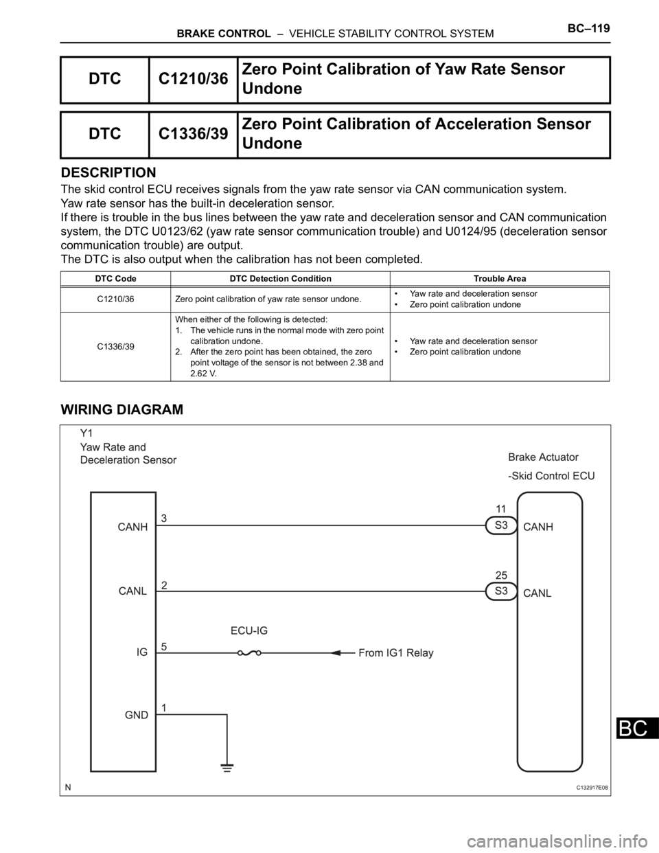
WIRING DIAGRAM
DTC C1210/36Zero Point Calibration of Yaw Rate Sensor
Undone
DTC C1336/39Zero Point Calibration of Acceleration Sensor
Undone
DTC Code DTC Detection Condition Trouble Area
C1210/36 Zero point calibration of yaw rate sensor undone.• Yaw rate and deceleration sensor
• Zero point calibration undone
C1336/39When either of the following is detected:
1. The vehicle runs in the normal mode with zero point
calibration undone.
2. After the zero point has been obtained, the zero
point voltage of the sensor is not between 2.38 and
2.62 V.• Yaw rate and deceleration sensor
• Zero point calibration undone
C132917E08
Page 2483 of 3000
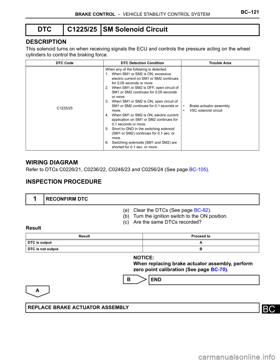
BRAKE CONTROL – VEHICLE STABILITY CONTROL SYSTEMBC–121
BC
DESCRIPTION
This solenoid turns on when receiving signals the ECU and controls the pressure acting on the wheel
cylinders to control the braking force.
WIRING DIAGRAM
Refer to DTCs C0226/21, C0236/22, C0246/23 and C0256/24 (See page BC-105).
INSPECTION PROCEDURE
(a) Clear the DTCs (See page BC-82).
(b) Turn the ignition switch to the ON position.
(c) Are the same DTCs recorded?
Result
NOTICE:
When replacing brake actuator assembly, perform
zero point calibration (See page BC-70).
B
A
DTC C1225/25 SM Solenoid Circuit
DTC Code DTC Detection Condition Trouble Area
C1225/25When any of the following is detected:
1. When SM1 or SM2 is ON, excessive
electric current on SM1 or SM2 continues
for 0.05 seconds or more.
2. When SM1 or SM2 is OFF, open circuit of
SM1 or SM2 continues for 0.05 seconds
or more.
3. When SM1 or SM2 is ON, open circuit of
SM1 or SM2 continues for 0.1 seconds or
more.
4. When SM1 or SM2 is ON, electric current
application on SM1 or SM2 continues for
0.1 seconds or more.
5. Short to GND in the switching solenoid
(SM1 or SM2) continues for 0.1 sec. or
more.
6. Switching solenoids (SM1 and SM2) are
shorted for 0.1 sec. or more.• Brake actuator assembly
• VSC solenoid circuit
1RECONFIRM DTC
Result Proceed to
DTC is outputA
DTC is not outputB
END
REPLACE BRAKE ACTUATOR ASSEMBLY
Page 2485 of 3000
BRAKE CONTROL – VEHICLE STABILITY CONTROL SYSTEMBC–123
BC
WIRING DIAGRAM
INSPECTION PROCEDURE
HINT:
• When U0073/94, U0100/65, U0123/62, U0124/95 or U0126/63 are output accompanied with C1231/
31, inspect and repair the trouble areas indicated by U0073/94, U0100/65, U0123/62, U0124/95 or
U0126/63 first.
F045127E03