Page 632 of 3000
2GR-FE ENGINE CONTROL SYSTEM – SFI SYSTEMES–339
ES
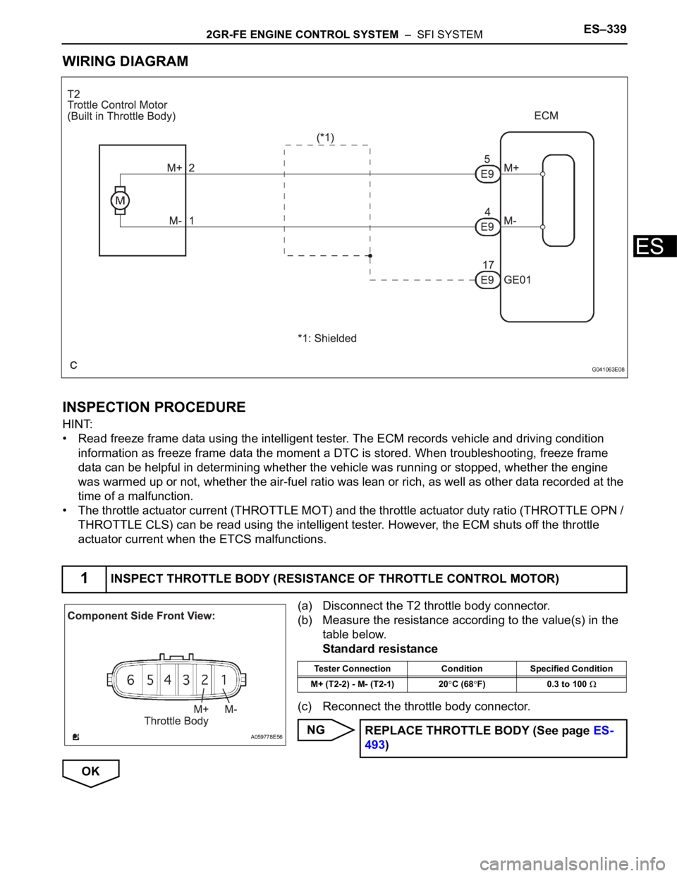
WIRING DIAGRAM
INSPECTION PROCEDURE
HINT:
• Read freeze frame data using the intelligent tester. The ECM records vehicle and driving condition
information as freeze frame data the moment a DTC is stored. When troubleshooting, freeze frame
data can be helpful in determining whether the vehicle was running or stopped, whether the engine
was warmed up or not, whether the air-fuel ratio was lean or rich, as well as other data recorded at the
time of a malfunction.
• The throttle actuator current (THROTTLE MOT) and the throttle actuator duty ratio (THROTTLE OPN /
THROTTLE CLS) can be read using the intelligent tester. However, the ECM shuts off the throttle
actuator current when the ETCS malfunctions.
(a) Disconnect the T2 throttle body connector.
(b) Measure the resistance according to the value(s) in the
table below.
Standard resistance
(c) Reconnect the throttle body connector.
NG
OK
1INSPECT THROTTLE BODY (RESISTANCE OF THROTTLE CONTROL MOTOR)
G041063E08
A059778E56
Tester Connection Condition Specified Condition
M+ (T2-2) - M- (T2-1) 20
C (68F) 0.3 to 100
REPLACE THROTTLE BODY (See page ES-
493)
Page 635 of 3000

ES–3422GR-FE ENGINE CONTROL SYSTEM – SFI SYSTEM
ES
*: System guard set when following conditions met
TYPICAL MALFUNCTION THRESHOLDS
P2111 (Throttle actuator stuck open):
P2112 (Throttle actuator stuck closed):
FA I L - S A F E
When either of these DTCs, as well as other DTCs relating to ETCS (Electronic Throttle Control System)
malfunctions, is set, the ECM enters fail-safe mode. During fail-safe mode, the ECM cuts the current to
the throttle actuator off, and the throttle valve is returned to a 6
throttle angle by the return spring. The
ECM then adjusts the engine output by controlling the fuel injection (intermittent fuel-cut) and ignition
timing, in accordance with the accelerator pedal opening angle, to allow the vehicle to continue at a
minimal speed.
If the accelerator pedal is depressed slowly, the vehicle can be driven slowly.
Fail-safe mode continues until a pass condition is detected, and the ignition switch is then turned off.
WIRING DIAGRAM
Refer to DTC P2102 (See page ES-331).
INSPECTION PROCEDURE
HINT:
Read freeze frame data using the intelligent tester. The ECM records vehicle and driving condition
information as freeze frame data the moment a DTC is stored. When troubleshooting, freeze frame data
can be helpful in determining whether the vehicle was running or stopped, whether the engine was
warmed up or not, whether the air-fuel ratio was lean or rich, as well as other data recorded at the time of
a malfunction.
(a) Connect the intelligent tester to the DLC3.
(b) Turn the ignition switch to the ON position.
(c) Turn the tester on.
(d) Select the following menu items: DIAGNOSIS /
ENHANCED OBD II / DTC INFO / CURRENT CODES.
(e) Read the DTCs.
Result
Throttle actuator open duty-cycle 80% or more
Throttle actuator ON
Throttle actuator duty calculation Executing
Throttle position sensor Fail determined
Throttle actuator current-cut operation Not executing
Throttle actuator power supply 4 V or more
Throttle actuator Fail determined
TP sensor voltage change No change
TP sensor voltage change No change
1CHECK ANY OTHER DTCS OUTPUT (IN ADDITION TO DTC P2111 OR P2112)
Display (DTC Output) Proceed to
P2111 or P2112 A
P2111 or P2112 and other DTCs B
Page 638 of 3000
2GR-FE ENGINE CONTROL SYSTEM – SFI SYSTEMES–345
ES
TYPICAL ENABLING CONDITIONS
TYPICAL MALFUNCTION THRESHOLDS
COMPONENT OPERATING RANGE
FAIL-SAFE
When this DTC, as well as other DTCs relating to ETCS (Electronic Throttle Control System)
malfunctions, is set, the ECM enters fail-safe mode. During fail-safe mode, the ECM cuts the current to
the throttle actuator off, and the throttle valve is returned to a 6
throttle angle by the return spring. The
ECM then adjusts the engine output by controlling the fuel injection (intermittent fuel-cut) and ignition
timing, in accordance with the accelerator pedal opening angle, to allow the vehicle to continue at a
minimal speed. If the accelerator pedal is depressed gently, the vehicle can be driven slowly.
Fail-safe mode continues until a pass condition is detected, and the ignition switch is then turned off.
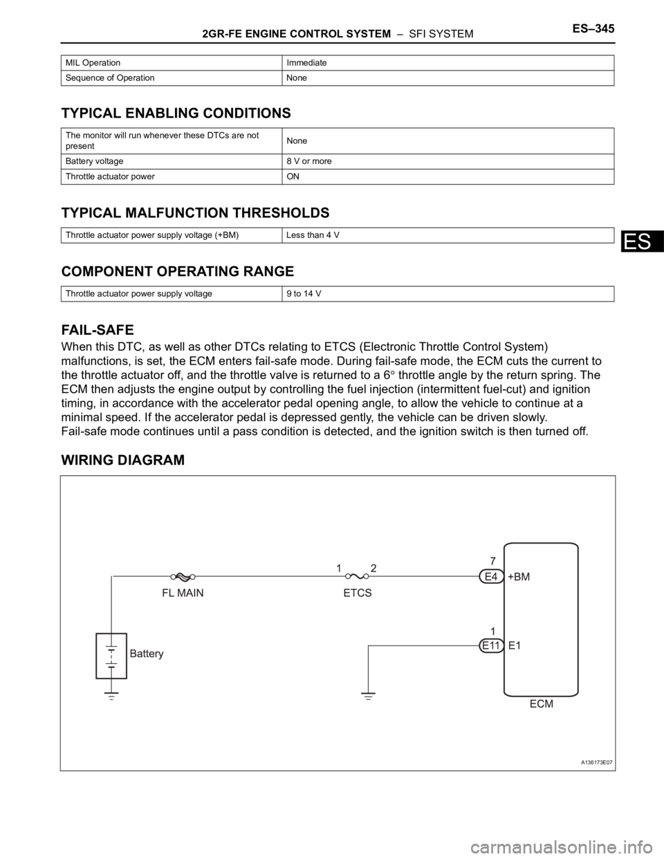
WIRING DIAGRAM
MIL Operation Immediate
Sequence of Operation None
The monitor will run whenever these DTCs are not
presentNone
Battery voltage 8 V or more
Throttle actuator power ON
Throttle actuator power supply voltage (+BM) Less than 4 V
Throttle actuator power supply voltage 9 to 14 V
A136173E07
Page 642 of 3000
2GR-FE ENGINE CONTROL SYSTEM – SFI SYSTEMES–349
ES
FAIL-SAFE
When this DTC, as well as other DTCs relating to ETCS (Electronic Throttle Control System)
malfunctions, is set, the ECM enters fail-safe mode. During fail-safe mode, the ECM cuts the current to
the throttle actuator off, and the throttle valve is returned to a 6
throttle angle by the return spring. The
ECM then adjusts the engine output by controlling the fuel injection (intermittent fuel-cut) and ignition
timing, in accordance with the accelerator pedal opening angle, to allow the vehicle to continue at a
minimal speed. If the accelerator pedal is depressed slowly, the vehicle can be driven slowly.
Fail-safe mode continues until a pass condition is detected, and the ignition switch is then turned off.
WIRING DIAGRAM
Refer to DTC P2102 (See page ES-331).
INSPECTION PROCEDURE
HINT:
Read freeze frame data using the intelligent tester. The ECM records vehicle and driving condition
information as freeze frame data the moment a DTC is stored. When troubleshooting, freeze frame data
can be helpful in determining whether the vehicle was running or stopped, whether the engine was
warmed up or not, whether the air-fuel ratio was lean or rich, as well as other data recorded at the time of
a malfunction.
(a) Connect the intelligent tester to the DLC3.
(b) Turn the ignition switch to the ON position.
(c) Turn the tester on.
(d) Select the following menu items: DIAGNOSIS /
ENHANCED OBD II / DTC INFO / CURRENT CODES.
(e) Read the DTCs.
Result
HINT:
If any DTCs other than P2119 are output, troubleshoot
those DTCs first.
B
A
(a) Connect the intelligent tester to the DLC3.
(b) Turn the ignition switch to the ON position.
(c) Turn the tester on.
(d) Clear the DTCs (See page ES-39).
(e) Allow the engine to idle for 15 seconds.
CAUTION:
Perform the procedures "A" and "B" below with
great care. Failure to do so may result in the vehicle
unexpectedly rolling away.
1CHECK ANY OTHER DTCS OUTPUT (IN ADDITION TO DTC P2119)
Display (DTC Output) Proceed to
P2119 A
P2119 and other DTCs B
GO TO DTC CHART (See page ES-56)
2CHECK WHETHER DTC OUTPUT RECURS (DTC P2119)
Page 648 of 3000
2GR-FE ENGINE CONTROL SYSTEM – SFI SYSTEMES–355
ES
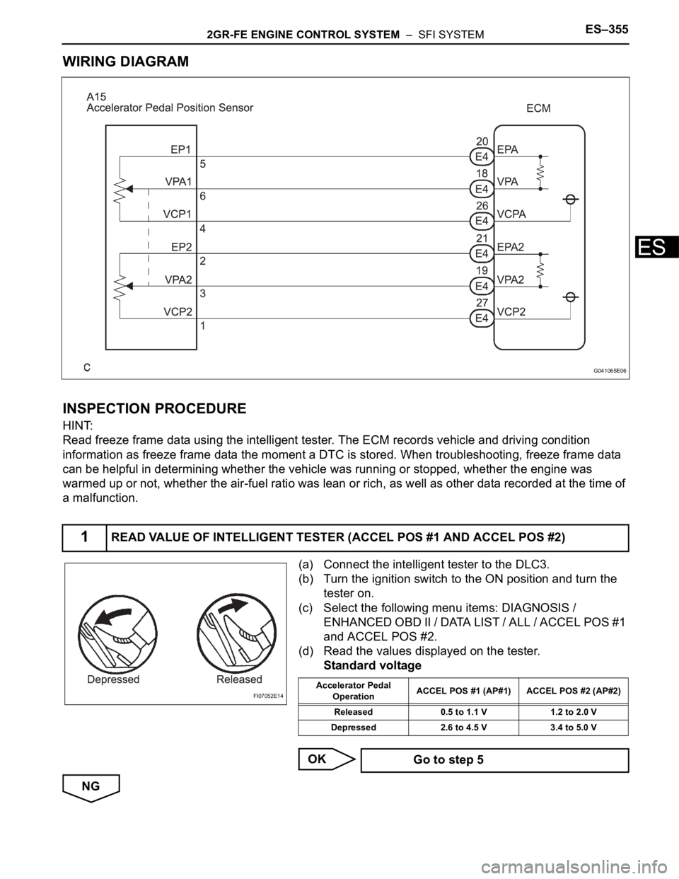
WIRING DIAGRAM
INSPECTION PROCEDURE
HINT:
Read freeze frame data using the intelligent tester. The ECM records vehicle and driving condition
information as freeze frame data the moment a DTC is stored. When troubleshooting, freeze frame data
can be helpful in determining whether the vehicle was running or stopped, whether the engine was
warmed up or not, whether the air-fuel ratio was lean or rich, as well as other data recorded at the time of
a malfunction.
(a) Connect the intelligent tester to the DLC3.
(b) Turn the ignition switch to the ON position and turn the
tester on.
(c) Select the following menu items: DIAGNOSIS /
ENHANCED OBD II / DATA LIST / ALL / ACCEL POS #1
and ACCEL POS #2.
(d) Read the values displayed on the tester.
Standard voltage
OK
NG
1READ VALUE OF INTELLIGENT TESTER (ACCEL POS #1 AND ACCEL POS #2)
G041065E06
FI07052E14Accelerator Pedal
OperationACCEL POS #1 (AP#1) ACCEL POS #2 (AP#2)
Released 0.5 to 1.1 V 1.2 to 2.0 V
Depressed 2.6 to 4.5 V 3.4 to 5.0 V
Go to step 5
Page 653 of 3000
ES–3602GR-FE ENGINE CONTROL SYSTEM – SFI SYSTEM
ES
If a pass condition is detected and then the ignition switch is turned off, the fail-safe operation stops and
the system returns to a normal condition.
WIRING DIAGRAM
Refer to DTC P2120 (See page ES-347).
INSPECTION PROCEDURE
HINT:
Read freeze frame data using the intelligent tester. The ECM records vehicle and driving condition
information as freeze frame data the moment a DTC is stored. When troubleshooting, freeze frame data
can be helpful in determining whether the vehicle was running or stopped, whether the engine was
warmed up or not, whether the air-fuel ratio was lean or rich, as well as other data recorded at the time of
a malfunction.
(a) Connect the intelligent tester to the DLC3.
(b) Turn the ignition switch to the ON position and turn the
tester on.
(c) Select the following menu items: DIAGNOSIS /
ENHANCED OBD II / DATA LIST / ALL / ACCEL POS #1
and ACCEL POS #2.
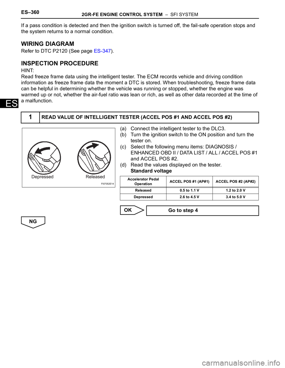
(d) Read the values displayed on the tester.
Standard voltage
OK
NG
1READ VALUE OF INTELLIGENT TESTER (ACCEL POS #1 AND ACCEL POS #2)
FI07052E14Accelerator Pedal
OperationACCEL POS #1 (AP#1) ACCEL POS #2 (AP#2)
Released 0.5 to 1.1 V 1.2 to 2.0 V
Depressed 2.6 to 4.5 V 3.4 to 5.0 V
Go to step 4
Page 660 of 3000
2GR-FE ENGINE CONTROL SYSTEM – SFI SYSTEMES–367
ES
WIRING DIAGRAM
CONFIRMATION DRIVING PATTERN
This confirmation driving pattern is used in steps 4, 7, 17, and 21 of the following diagnostic
troubleshooting procedure when using the intelligent tester.
A165206E01
Page 675 of 3000

ES–3822GR-FE ENGINE CONTROL SYSTEM – SFI SYSTEM
ES
Others:
TYPICAL MALFUNCTION THRESHOLDS
P2238 and P2241 (Open circuit between AF+ and AF-):
P2238 and P2241 (Short circuit between AF+ and GND):
P2238 and P2241 (Short circuit between AF+ and AF-):
P2239 and P2242 (Short circuit between AF+ and +B):
P2252 and P2255 (Short circuit between AF- and GND):
P2253 and P2256 (Short circuit between AF- and +B):
WIRING DIAGRAM
Refer to DTC P2195 (See page ES-359).
INSPECTION PROCEDURE
HINT:
For use of the intelligent tester only:
Malfunctioning areas can be identified by performing the A/F CONTROL function provided in the ACTIVE
TEST. The A/F CONTROL function can help to determine whether the Air-Fuel Ratio (A/F) sensor, Heated
Oxygen (HO2) sensor and other potential trouble areas are malfunctioning.
The following instructions describe how to conduct the A/F CONTROL operation using the intelligent
tester.
(a) Connect the intelligent tester to the DLC3.
(b) Start the engine and turn the tester on.
(c) Warm up the engine at an engine speed of 2500 rpm for approximately 90 seconds.
(d) Select the following menu items on the tester: DIAGNOSIS / ENHANCED OBD II / ACTIVE TEST / A/
F CONTROL.
(e) Perform the A/F CONTROL operation with the engine in an idling condition (press the RIGHT or LEFT
button to change the fuel injection volume).
Engine Running
Fuel-cut OFF
Time after fuel-cut OFF 5 seconds or more
A/F sensor heater ON
Battery voltage 11 V or more
Ignition switch ON
Time after ignition switch is OFF to ON 5 seconds or more
Battery voltage 11 V or more
Ignition switch ON
Time after ignition switch is OFF to ON 5 seconds or more
A/F sensor admittance Below 0.022 1/
AF+ terminal voltage 0.5 V or less
Difference between AF+ terminal and AF- terminal
voltage0.1 V or less
AF+ terminal voltage More than 4.5 V
AF- terminal voltage 0.5 V or less
AF- terminal voltage More than 4.5 V