2007 TOYOTA SIENNA ECU
[x] Cancel search: ECUPage 627 of 3000

ES–3342GR-FE ENGINE CONTROL SYSTEM – SFI SYSTEM
ES
DESCRIPTION
The ECM monitors the output voltage to the throttle actuator. This self-check ensures that the ECM is
functioning properly. The output voltage is usually 0 V when the ignition switch is turned off. If the output
voltage is higher than 7 volts when the ignition switch is turned off, the ECM will illuminate the MIL and set
a DTC when the ignition switch is turned on.
MONITOR STRATEGY
TYPICAL ENABLING CONDITIONS
TYPICAL MALFUNCTION THRESHOLDS
INSPECTION PROCEDURE
(a) Connect the intelligent tester to the DLC3.
(b) Turn the ignition switch to the ON position.
(c) Turn the tester on.
(d) Clear the DTC.
(e) Turn the ignition switch off.
(f) Disconnect the battery negative terminal and wait for 1
minute.
(g) Connect the battery negative terminal.
(h) Turn the ignition switch to the ON position for 10
seconds.
(i) Turn the ignition switch off.
(j) Turn the ignition switch to the ON position.
(k) Enter the following menus: DIAGNOSIS / ENHANCED II
/ DTC INFO / CURRENT CODES.
(l) Read the DTCs.
DTC P0657 Actuator Supply Voltage Circuit / Open
DTC DTC Detection Condition Trouble Area
P0657 Throttle actuator power supply error ECM
Related DTC P0657: ETCS power supply
Required sensors/Components (main) ECM
Required sensors/Components (sub) Throttle actuator
Frequency of Operation Once per driving cycle
Duration Within 1 second
MIL Operation Immediate
Sequence of Operation None
Monitor will run whenever this DTC is not present None
Ignition switch From ON to OFF
Throttle actuator power supply 7 V or more
1CHECK WHETHER DTC OUTPUT RECURS (IN ADDITION TO DTC P0657)
Page 635 of 3000

ES–3422GR-FE ENGINE CONTROL SYSTEM – SFI SYSTEM
ES
*: System guard set when following conditions met
TYPICAL MALFUNCTION THRESHOLDS
P2111 (Throttle actuator stuck open):
P2112 (Throttle actuator stuck closed):
FA I L - S A F E
When either of these DTCs, as well as other DTCs relating to ETCS (Electronic Throttle Control System)
malfunctions, is set, the ECM enters fail-safe mode. During fail-safe mode, the ECM cuts the current to
the throttle actuator off, and the throttle valve is returned to a 6
throttle angle by the return spring. The
ECM then adjusts the engine output by controlling the fuel injection (intermittent fuel-cut) and ignition
timing, in accordance with the accelerator pedal opening angle, to allow the vehicle to continue at a
minimal speed.
If the accelerator pedal is depressed slowly, the vehicle can be driven slowly.
Fail-safe mode continues until a pass condition is detected, and the ignition switch is then turned off.
WIRING DIAGRAM
Refer to DTC P2102 (See page ES-331).
INSPECTION PROCEDURE
HINT:
Read freeze frame data using the intelligent tester. The ECM records vehicle and driving condition
information as freeze frame data the moment a DTC is stored. When troubleshooting, freeze frame data
can be helpful in determining whether the vehicle was running or stopped, whether the engine was
warmed up or not, whether the air-fuel ratio was lean or rich, as well as other data recorded at the time of
a malfunction.
(a) Connect the intelligent tester to the DLC3.
(b) Turn the ignition switch to the ON position.
(c) Turn the tester on.
(d) Select the following menu items: DIAGNOSIS /
ENHANCED OBD II / DTC INFO / CURRENT CODES.
(e) Read the DTCs.
Result
Throttle actuator open duty-cycle 80% or more
Throttle actuator ON
Throttle actuator duty calculation Executing
Throttle position sensor Fail determined
Throttle actuator current-cut operation Not executing
Throttle actuator power supply 4 V or more
Throttle actuator Fail determined
TP sensor voltage change No change
TP sensor voltage change No change
1CHECK ANY OTHER DTCS OUTPUT (IN ADDITION TO DTC P2111 OR P2112)
Display (DTC Output) Proceed to
P2111 or P2112 A
P2111 or P2112 and other DTCs B
Page 636 of 3000
2GR-FE ENGINE CONTROL SYSTEM – SFI SYSTEMES–343
ES
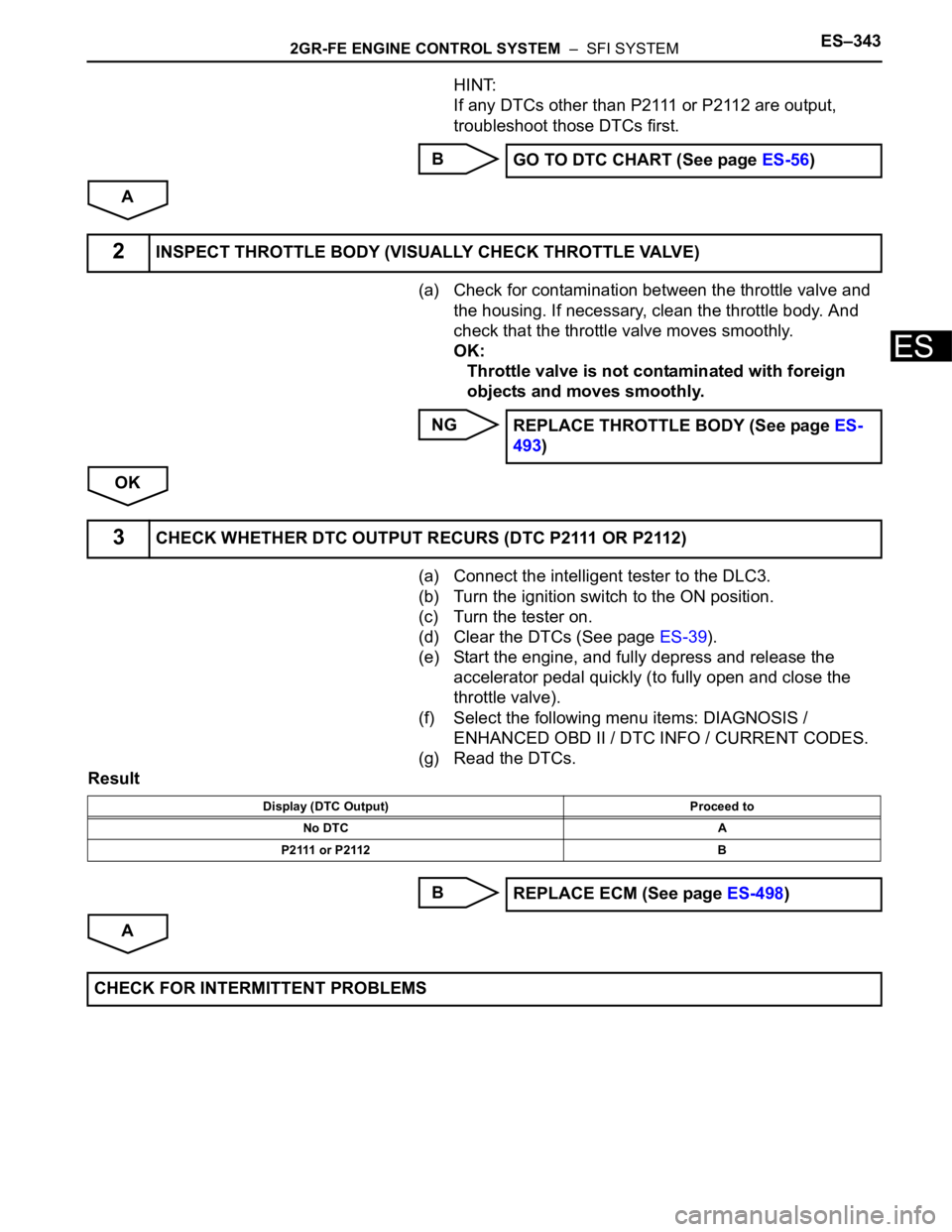
HINT:
If any DTCs other than P2111 or P2112 are output,
troubleshoot those DTCs first.
B
A
(a) Check for contamination between the throttle valve and
the housing. If necessary, clean the throttle body. And
check that the throttle valve moves smoothly.
OK:
Throttle valve is not contaminated with foreign
objects and moves smoothly.
NG
OK
(a) Connect the intelligent tester to the DLC3.
(b) Turn the ignition switch to the ON position.
(c) Turn the tester on.
(d) Clear the DTCs (See page ES-39).
(e) Start the engine, and fully depress and release the
accelerator pedal quickly (to fully open and close the
throttle valve).
(f) Select the following menu items: DIAGNOSIS /
ENHANCED OBD II / DTC INFO / CURRENT CODES.
(g) Read the DTCs.
Result
B
AGO TO DTC CHART (See page ES-56)
2INSPECT THROTTLE BODY (VISUALLY CHECK THROTTLE VALVE)
REPLACE THROTTLE BODY (See page ES-
493)
3CHECK WHETHER DTC OUTPUT RECURS (DTC P2111 OR P2112)
Display (DTC Output) Proceed to
No DTC A
P 2 111 o r P 2 11 2 B
REPLACE ECM (See page ES-498)
CHECK FOR INTERMITTENT PROBLEMS
Page 641 of 3000

ES–3482GR-FE ENGINE CONTROL SYSTEM – SFI SYSTEM
ES
DESCRIPTION
The Electronic Throttle Control System (ETCS) is composed of the throttle actuator, Throttle Position (TP)
sensor, Accelerator Pedal Position (APP) sensor, and ECM. The ECM operates the throttle actuator to
regulate the throttle valve in response to driver inputs. The TP sensor detects the opening angle of the
throttle valve, and provides the ECM with feedback so that the throttle valve can be appropriately
controlled by the ECM.
MONITOR DESCRIPTION
The ECM determines the actual opening angle of the throttle valve from the TP sensor signal. The actual
opening angle is compared to the target opening angle commanded by the ECM. If the difference
between these two values is outside the standard range, the ECM interprets this as a malfunction in the
ETCS. The ECM then illuminates the MIL and sets the DTC.
If the malfunction is not repaired successfully, the DTC is set when the accelerator pedal is quickly
released (to close the throttle valve) after the engine speed reaches 5000 rpm by the accelerator pedal
being fully depressed (fully open the throttle valve).
MONITOR STRATEGY
TYPICAL ENABLING CONDITIONS
TYPICAL MALFUNCTION THRESHOLDS
DTC P2119Throttle Actuator Control Throttle Body Range /
Performance
DTC No. DTC Detection Condition Trouble Area
P2119Throttle valve opening angle continues to vary greatly
from target opening angle (1 trip detection logic)•ETCS
•ECM
Related DTCs P2119: ETCS malfunction
Required Sensors / Components (Main) Throttle actuator
Required Sensors / Components (Related) -
Frequency of Operation Continuous
Duration 1 second
MIL Operation Immediate
Sequence of Operation None
The monitor will run whenever these DTCs are not
presentNone
System guard* ON
*System guard set when the following conditions are
met-
Throttle actuator ON
Throttle actuator duty calculation Executing
TP sensor Fail determined
Throttle actuator current-cut Not executing
Throttle actuator power supply 4 V or more
Throttle actuator Fail determined
Either of following conditions is met Condition A or B
A. Commanded closed TP - current closed TP 0.3 V or more
B. Commanded open TP - current open TP 0.3 V or more
Page 642 of 3000
2GR-FE ENGINE CONTROL SYSTEM – SFI SYSTEMES–349
ES
FAIL-SAFE
When this DTC, as well as other DTCs relating to ETCS (Electronic Throttle Control System)
malfunctions, is set, the ECM enters fail-safe mode. During fail-safe mode, the ECM cuts the current to
the throttle actuator off, and the throttle valve is returned to a 6
throttle angle by the return spring. The
ECM then adjusts the engine output by controlling the fuel injection (intermittent fuel-cut) and ignition
timing, in accordance with the accelerator pedal opening angle, to allow the vehicle to continue at a
minimal speed. If the accelerator pedal is depressed slowly, the vehicle can be driven slowly.
Fail-safe mode continues until a pass condition is detected, and the ignition switch is then turned off.
WIRING DIAGRAM
Refer to DTC P2102 (See page ES-331).
INSPECTION PROCEDURE
HINT:
Read freeze frame data using the intelligent tester. The ECM records vehicle and driving condition
information as freeze frame data the moment a DTC is stored. When troubleshooting, freeze frame data
can be helpful in determining whether the vehicle was running or stopped, whether the engine was
warmed up or not, whether the air-fuel ratio was lean or rich, as well as other data recorded at the time of
a malfunction.
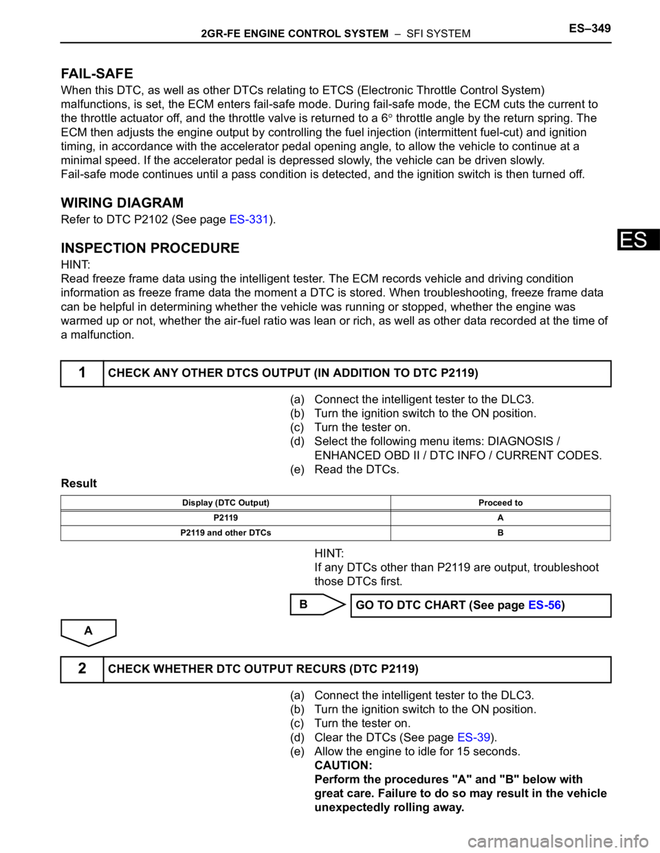
(a) Connect the intelligent tester to the DLC3.
(b) Turn the ignition switch to the ON position.
(c) Turn the tester on.
(d) Select the following menu items: DIAGNOSIS /
ENHANCED OBD II / DTC INFO / CURRENT CODES.
(e) Read the DTCs.
Result
HINT:
If any DTCs other than P2119 are output, troubleshoot
those DTCs first.
B
A
(a) Connect the intelligent tester to the DLC3.
(b) Turn the ignition switch to the ON position.
(c) Turn the tester on.
(d) Clear the DTCs (See page ES-39).
(e) Allow the engine to idle for 15 seconds.
CAUTION:
Perform the procedures "A" and "B" below with
great care. Failure to do so may result in the vehicle
unexpectedly rolling away.
1CHECK ANY OTHER DTCS OUTPUT (IN ADDITION TO DTC P2119)
Display (DTC Output) Proceed to
P2119 A
P2119 and other DTCs B
GO TO DTC CHART (See page ES-56)
2CHECK WHETHER DTC OUTPUT RECURS (DTC P2119)
Page 643 of 3000
ES–3502GR-FE ENGINE CONTROL SYSTEM – SFI SYSTEM
ES
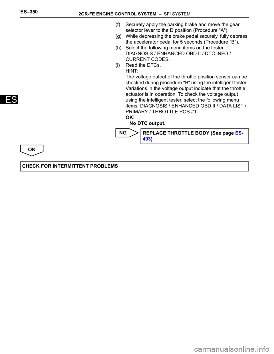
(f) Securely apply the parking brake and move the gear
selector lever to the D position (Procedure "A").
(g) While depressing the brake pedal securely, fully depress
the accelerator pedal for 5 seconds (Procedure "B").
(h) Select the following menu items on the tester:
DIAGNOSIS / ENHANCED OBD II / DTC INFO /
CURRENT CODES.
(i) Read the DTCs.
HINT:
The voltage output of the throttle position sensor can be
checked during procedure "B" using the intelligent tester.
Variations in the voltage output indicate that the throttle
actuator is in operation. To check the voltage output
using the intelligent tester, select the following menu
items: DIAGNOSIS / ENHANCED OBD II / DATA LIST /
PRIMARY / THROTTLE POS #1.
OK:
No DTC output.
NG
OKREPLACE THROTTLE BODY (See page ES-
493)
CHECK FOR INTERMITTENT PROBLEMS
Page 650 of 3000
2GR-FE ENGINE CONTROL SYSTEM – SFI SYSTEMES–357
ES
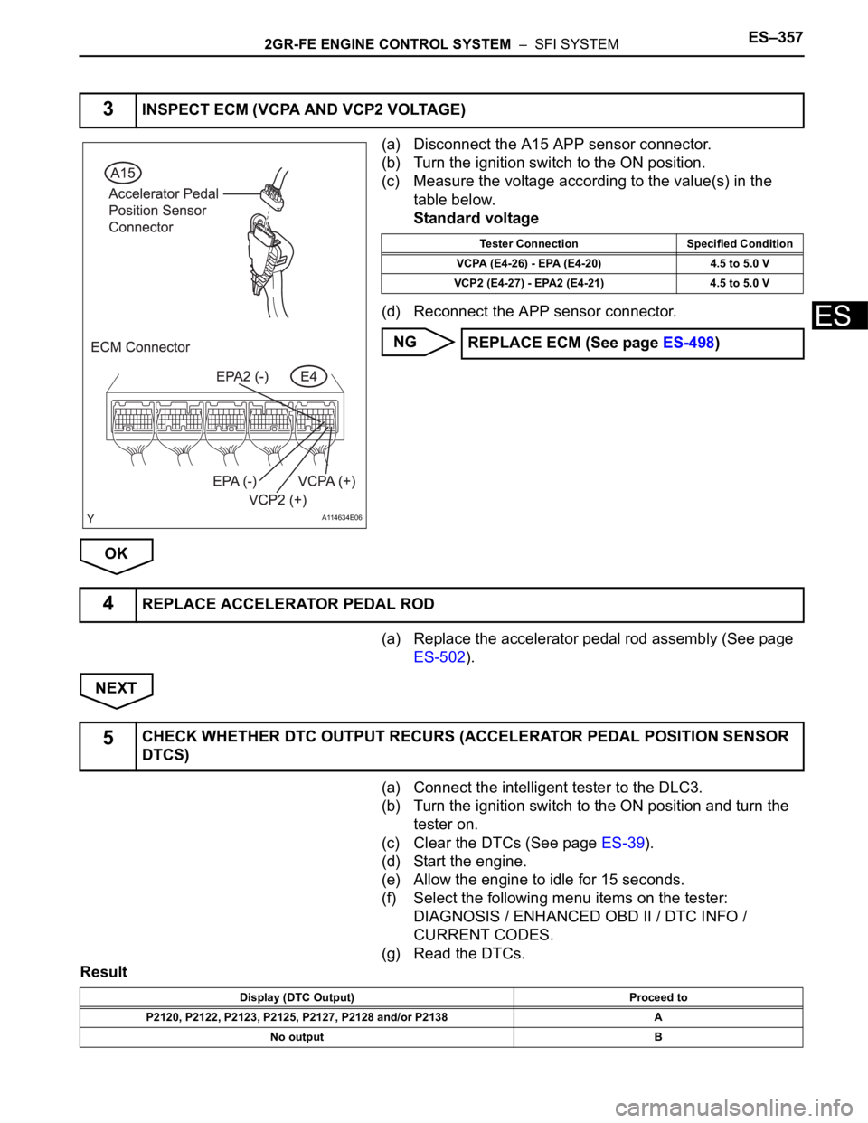
(a) Disconnect the A15 APP sensor connector.
(b) Turn the ignition switch to the ON position.
(c) Measure the voltage according to the value(s) in the
table below.
Standard voltage
(d) Reconnect the APP sensor connector.
NG
OK
(a) Replace the accelerator pedal rod assembly (See page
ES-502).
NEXT
(a) Connect the intelligent tester to the DLC3.
(b) Turn the ignition switch to the ON position and turn the
tester on.
(c) Clear the DTCs (See page ES-39).
(d) Start the engine.
(e) Allow the engine to idle for 15 seconds.
(f) Select the following menu items on the tester:
DIAGNOSIS / ENHANCED OBD II / DTC INFO /
CURRENT CODES.
(g) Read the DTCs.
Result
3INSPECT ECM (VCPA AND VCP2 VOLTAGE)
A114634E06
Tester Connection Specified Condition
VCPA (E4-26) - EPA (E4-20) 4.5 to 5.0 V
VCP2 (E4-27) - EPA2 (E4-21) 4.5 to 5.0 V
REPLACE ECM (See page ES-498)
4REPLACE ACCELERATOR PEDAL ROD
5CHECK WHETHER DTC OUTPUT RECURS (ACCELERATOR PEDAL POSITION SENSOR
DTCS)
Display (DTC Output) Proceed to
P2120, P2122, P2123, P2125, P2127, P2128 and/or P2138 A
No output B
Page 654 of 3000
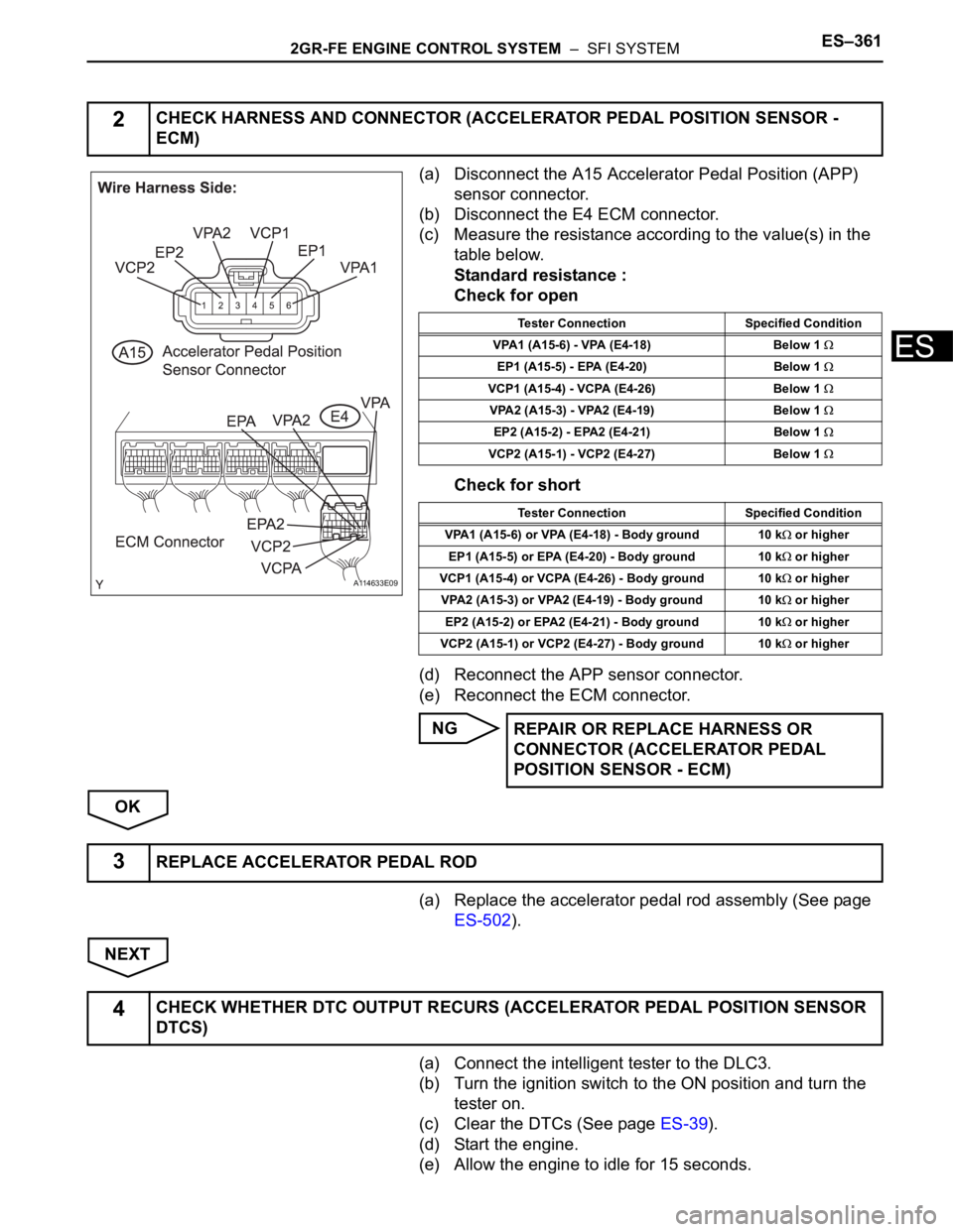
2GR-FE ENGINE CONTROL SYSTEM – SFI SYSTEMES–361
ES
(a) Disconnect the A15 Accelerator Pedal Position (APP)
sensor connector.
(b) Disconnect the E4 ECM connector.
(c) Measure the resistance according to the value(s) in the
table below.
Standard resistance :
Check for open
Check for short
(d) Reconnect the APP sensor connector.
(e) Reconnect the ECM connector.
NG
OK
(a) Replace the accelerator pedal rod assembly (See page
ES-502).
NEXT
(a) Connect the intelligent tester to the DLC3.
(b) Turn the ignition switch to the ON position and turn the
tester on.
(c) Clear the DTCs (See page ES-39).
(d) Start the engine.
(e) Allow the engine to idle for 15 seconds.
2CHECK HARNESS AND CONNECTOR (ACCELERATOR PEDAL POSITION SENSOR -
ECM)
A114633E09
Tester Connection Specified Condition
VPA1 (A15-6) - VPA (E4-18) Below 1
EP1 (A15-5) - EPA (E4-20) Below 1
VCP1 (A15-4) - VCPA (E4-26) Below 1
VPA2 (A15-3) - VPA2 (E4-19) Below 1
EP2 (A15-2) - EPA2 (E4-21) Below 1
VCP2 (A15-1) - VCP2 (E4-27) Below 1
Tester Connection Specified Condition
VPA1 (A15-6) or VPA (E4-18) - Body ground 10 k
or higher
EP1 (A15-5) or EPA (E4-20) - Body ground 10 k
or higher
VCP1 (A15-4) or VCPA (E4-26) - Body ground 10 k
or higher
VPA2 (A15-3) or VPA2 (E4-19) - Body ground 10 k
or higher
EP2 (A15-2) or EPA2 (E4-21) - Body ground 10 k
or higher
VCP2 (A15-1) or VCP2 (E4-27) - Body ground 10 k
or higher
REPAIR OR REPLACE HARNESS OR
CONNECTOR (ACCELERATOR PEDAL
POSITION SENSOR - ECM)
3REPLACE ACCELERATOR PEDAL ROD
4CHECK WHETHER DTC OUTPUT RECURS (ACCELERATOR PEDAL POSITION SENSOR
DTCS)