Page 429 of 3000
2GR-FE ENGINE CONTROL SYSTEM – SFI SYSTEMES–123
ES
OK
(a) Connect the intelligent tester to the DLC3.
(b) Turn the ignition switch to the ON position.
(c) Turn the intelligent tester ON.
(d) Clear the DTCs (See page ES-39).
(e) Start the engine.
(f) Allow the engine to idle for 1 minute or more.
(g) Select the following menu items: DIAGNOSIS /
ENHANCED OBD II / DTC INFO / CURRENT CODES.
(h) Read the DTCs.
Result
B
A
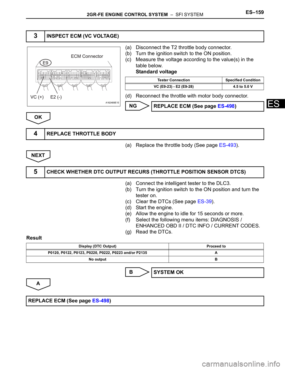
6CHECK WHETHER DTC OUTPUT RECURS
Display (DTC Output) Proceed to
No output A
P0037, P0038, P0057, P0058, P0141 and/or P0161 B
REPLACE ECM
CHECK FOR INTERMITTENT PROBLEMS
Page 465 of 3000

2GR-FE ENGINE CONTROL SYSTEM – SFI SYSTEMES–159
ES
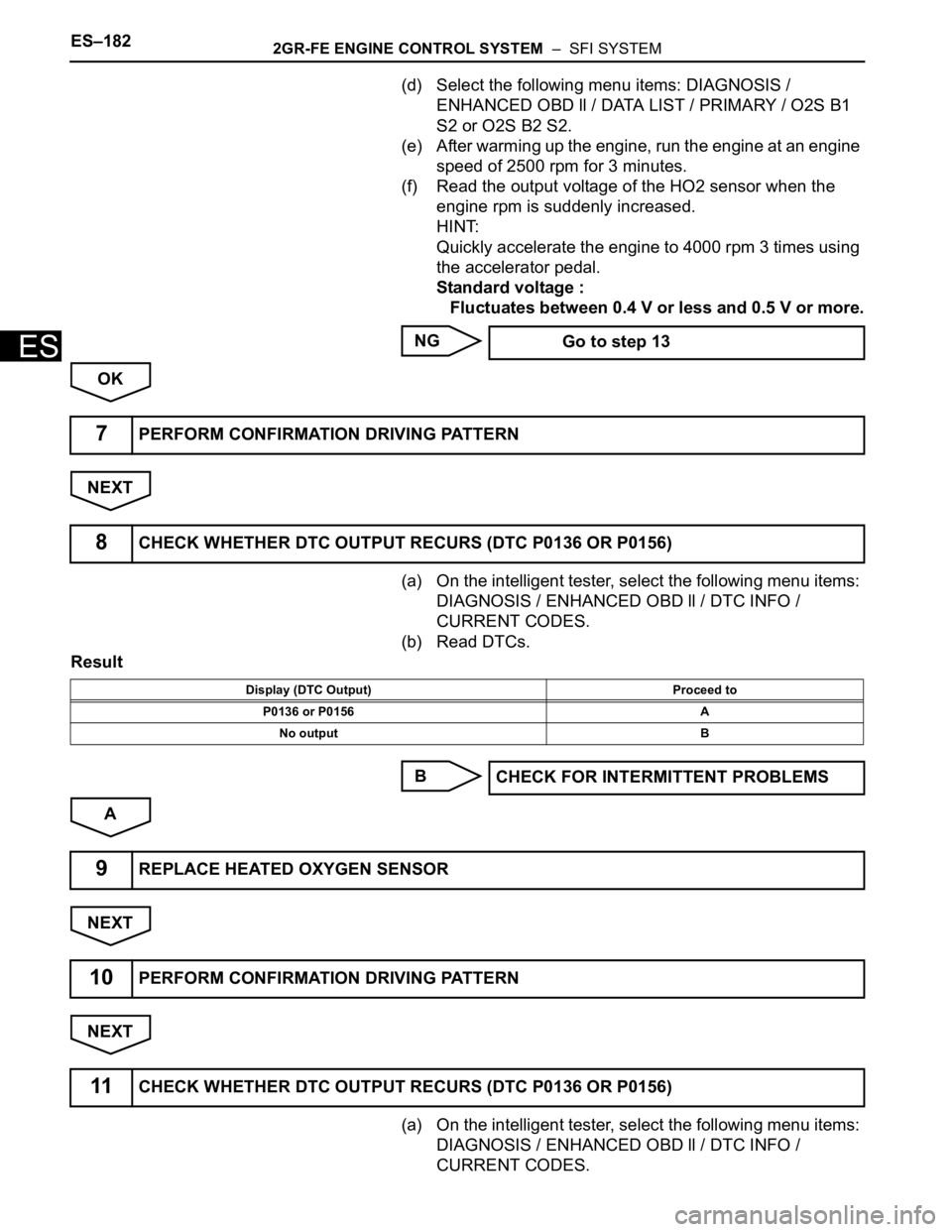
(a) Disconnect the T2 throttle body connector.
(b) Turn the ignition switch to the ON position.
(c) Measure the voltage according to the value(s) in the
table below.
Standard voltage
(d) Reconnect the throttle with motor body connector.
NG
OK
(a) Replace the throttle body (See page ES-493).
NEXT
(a) Connect the intelligent tester to the DLC3.
(b) Turn the ignition switch to the ON position and turn the
tester on.
(c) Clear the DTCs (See page ES-39).
(d) Start the engine.
(e) Allow the engine to idle for 15 seconds or more.
(f) Select the following menu items: DIAGNOSIS /
ENHANCED OBD II / DTC INFO / CURRENT CODES.
(g) Read the DTCs.
Result
B
A
3INSPECT ECM (VC VOLTAGE)
A162489E15
Tester Connection Specified Condition
VC (E9-23) - E2 (E9-28) 4.5 to 5.0 V
REPLACE ECM (See page ES-498)
4REPLACE THROTTLE BODY
5CHECK WHETHER DTC OUTPUT RECURS (THROTTLE POSITION SENSOR DTCS)
Display (DTC Output) Proceed to
P0120, P0122, P0123, P0220, P0222, P0223 and/or P2135 A
No output B
SYSTEM OK
REPLACE ECM (See page ES-498)
Page 488 of 3000

ES–1822GR-FE ENGINE CONTROL SYSTEM – SFI SYSTEM
ES
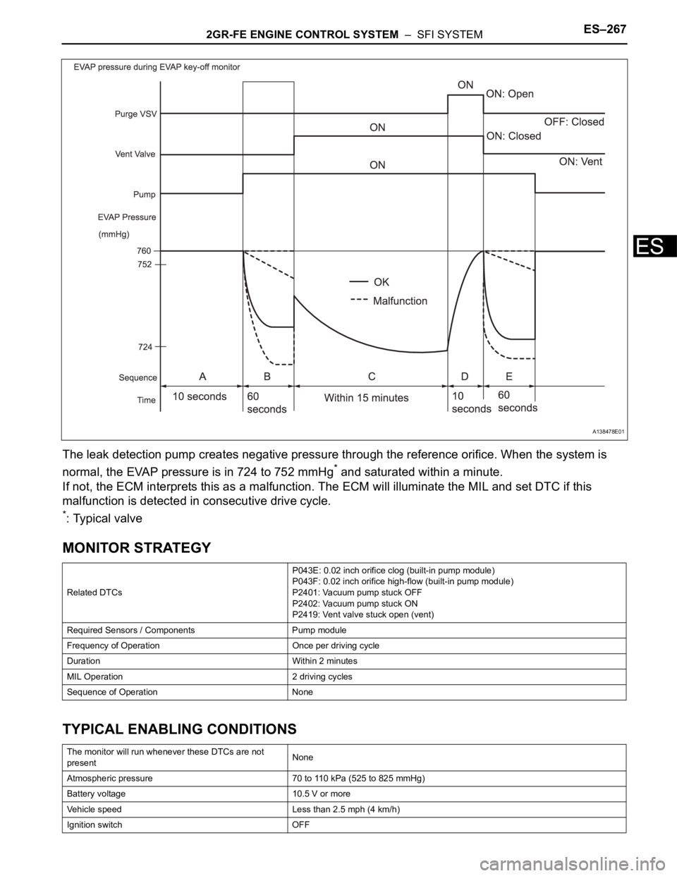
(d) Select the following menu items: DIAGNOSIS /
ENHANCED OBD ll / DATA LIST / PRIMARY / O2S B1
S2 or O2S B2 S2.
(e) After warming up the engine, run the engine at an engine
speed of 2500 rpm for 3 minutes.
(f) Read the output voltage of the HO2 sensor when the
engine rpm is suddenly increased.
HINT:
Quickly accelerate the engine to 4000 rpm 3 times using
the accelerator pedal.
Standard voltage :
Fluctuates between 0.4 V or less and 0.5 V or more.
NG
OK
NEXT
(a) On the intelligent tester, select the following menu items:
DIAGNOSIS / ENHANCED OBD ll / DTC INFO /
CURRENT CODES.
(b) Read DTCs.
Result
B
A
NEXT
NEXT
(a) On the intelligent tester, select the following menu items:
DIAGNOSIS / ENHANCED OBD ll / DTC INFO /
CURRENT CODES. Go to step 13
7PERFORM CONFIRMATION DRIVING PATTERN
8CHECK WHETHER DTC OUTPUT RECURS (DTC P0136 OR P0156)
Display (DTC Output) Proceed to
P0136 or P0156 A
No output B
CHECK FOR INTERMITTENT PROBLEMS
9REPLACE HEATED OXYGEN SENSOR
10PERFORM CONFIRMATION DRIVING PATTERN
11CHECK WHETHER DTC OUTPUT RECURS (DTC P0136 OR P0156)
Page 496 of 3000

ES–1902GR-FE ENGINE CONTROL SYSTEM – SFI SYSTEM
ES
TYPICAL ENABLING CONDITIONS
Fuel-trim:
TYPICAL MALFUNCTION THRESHOLDS
Fuel trim:
WIRING DIAGRAM
Refer to DTC P2195 (See page ES-359).
INSPECTION PROCEDURE
HINT:
For use of the intelligent tester only:
Malfunctioning areas can be identified by performing the A/F CONTROL function provided in the ACTIVE
TEST. The A/F CONTROL function can help to determine whether the Air-Fuel Ratio (A/F) sensor, Heated
Oxygen (HO2) sensor and other potential trouble areas are malfunctioning.
The following instructions describe how to conduct the A/F CONTROL operation using the intelligent
tester.
1. Connect the intelligent tester to the DLC3.
2. Start the engine and turn the tester on.
3. Warm up the engine at an engine speed of 2500 rpm for approximately 90 seconds.
4. Select the following menu items on the tester: DIAGNOSIS / ENHANCED OBD II / ACTIVE TEST / A/F
CONTROL.
5. Perform the A/F CONTROL operation with the engine in an idling condition (press the RIGHT or LEFT
button to change the fuel injection volume).
6. Monitor the voltage outputs of the A/F and HO2 sensors (AFS B1S1 and O2S B1S2 or AFS B2S1 and
O2S B2S2) displayed on the tester.
HINT:
• The A/F CONTROL operation lowers the fuel injection volume by 12.5% or increases the injection
volume by 25%.
• Each sensor reacts in accordance with increases and decreases in the fuel injection volume.
Standard voltage
The monitor will run whenever these DTCs are not
presentP0010, P0020 (VVT VSV1, 2), P0011, P0012 (VVT System-Advance, Retard),
P0021, P0022 (VVT System 2-Adavance, Retard), P0031, P0032, P0051, P0052 (A/
F Sensor Heater Sensor 1), P0100, P0101, P0102, P0103 (MAF Sensor), P0115,
P0116, P0117, P0118 (ECT Sensor), P0120, P0121, P0122, P0123, P0220, P0222,
P0223, P2135 (TP Sensor), P0125 (Insufficient ECT for Closed Loop), P0335 (CKP
Sensor), P0340 (CMP Sensor), P0351, P0352, P0353, P0354, P0356 (Ignitor),
P0500 (VSS)
Fuel system status Closed-loop
Battery voltage 11 V or more
Either of the following conditions is met Condition 1 or 2
1. Engine RPM Less than 1100 rpm
2. Intake air amount per revolution 0.22 g/rev or more
Catalyst monitor Not executed
EVAP purge-cut Executing
Either of the following conditions is met Condition 1 or 2
1. Average between short-term fuel trim and long-term
fuel trim35% or more at 80
C (176F) of ECT
2. Average between short-term fuel trim and long-term
fuel trim-35% or less at 80
C (176F) of ECT
Tester Display (Sensor) Injection Volumes Status Voltages
AFS B1S1 or AFS B2S1 (A/F) +25% Rich Less than 3.0
Page 505 of 3000
2GR-FE ENGINE CONTROL SYSTEM – SFI SYSTEMES–199
ES
HINT:
If the system is still malfunctioning, the MIL will be
illuminated during procedure "F".
NOTICE:
If the conditions in this test are not strictly followed,
no malfunction will be detected.
NEXT
(a) Select the following menu items: DIAGNOSIS /
ENHANCED OBD II / DTC INFO / PENDING CODES.
(b) Read the DTCs.
Result
B
A
A163945E02
16CHECK WHETHER DTC OUTPUT RECURS (DTC P0171, P0172, P0174 OR P0175)
Display (DTC Output) Proceed to
No output A
P0171, P0172, P0174 or P0175 B
Go to step 5
END
Page 514 of 3000

ES–2082GR-FE ENGINE CONTROL SYSTEM – SFI SYSTEM
ES
7. Drive the vehicle several times with the conditions, such as engine rpm and engine load, shown in
MISFIRE RPM and MISFIRE LOAD in the Data List.
HINT:
• In order to store misfire DTCs, it is necessary to operate the vehicle for the period of time shown in
the table below, using the MISFIRE RPM and MISFIRE LOAD in the Data List.
8. Check whether misfires have occurred by checking DTCs and freeze frame data.
HINT:
Do not turn the ignition switch off until the stored DTC(s) and freeze frame data have been recorded.
When the ECM returns to normal mode (default), the stored DTC(s), freeze frame data and other data
will be erased.
9. Record the DTC(s), freeze frame data and misfire counts.
10.Turn the ignition switch OFF and wait for at least 5 seconds.
INSPECTION PROCEDURE
HINT:
• If any DTCs other than misfire DTCs are output, troubleshoot those DTCs first.
• Read freeze frame data using the intelligent tester or Techstream. Freeze frame data records the
engine condition when malfunctions are detected. When troubleshooting, freeze frame data can help
determine if the vehicle was moving or stationary, if the engine was warmed up or not, if the air-fuel
ratio was lean or rich, and other data from the time the malfunction occurred.
• If the misfire does not recur when the vehicle is brought to the workshop, reproduce the conditions
stored in the ECM as freeze frame data.
• If the misfire still cannot be reproduced even though the conditions stored in the ECM as freeze frame
data have been reproduced, one of the following factors is considered to be a possible cause of the
problem:
(a) There was insufficient fuel volume in the tank.
(b) Improper fuel is used.
(c) The spark plugs have been contaminated.
• After finishing repairs, check the misfire counts of the cylinders (CYL #1, #2, #3, #4, #5, #6).
• Be sure to confirm that no misfiring cylinder DTCs are set again by conducting the confirmation driving
pattern after finishing repairs.
• For 6 and 8 cylinder engines, the ECM intentionally does not set the specific misfiring cylinder DTCs at
high engine RPM. If misfires occur only in high engine RPM areas, only DTC P0300 is set.
In the event of DTC P0300 being present, perform the following operations:
(a) Clear the DTC (See page ES-39).
(b) Start the engine and conduct the confirmation driving pattern.
(c) Read the misfiring rates of each cylinder or DTC(s) using the tester.
(d) Repair the cylinder(s) that has a high misfiring rate or is indicated by the DTC.
(e) After finishing repairs, conduct the confirmation driving pattern again, in order to verify that DTC
P0300 is not set.
• When one of SHORT FT #1, LONG FT #1, SHORT FT #2 or LONG FT #2 in the freeze frame data is
outside the range of +/-20%, the air-fuel ratio may be Rich (-20% or less) or Lean (+20% or more).
• When the COOLANT TEMP in the freeze frame data is less than 75
C (167F), the misfire have
occurred only while warming up the engine.
Engine RPM Duration
Idling 3.5 minutes or more
1000 3 minutes or more
2000 1.5 minutes or more
3000 1 minute or more
Page 545 of 3000
2GR-FE ENGINE CONTROL SYSTEM – SFI SYSTEMES–239
ES
NG
OK
(a) Replace the VVT sensor (See page ES-509).
NEXT
(a) Connect the intelligent tester to the DLC3.
(b) Turn the ignition switch to the ON position.
(c) Turn the intelligent tester on.
(d) Clear the DTCs.
(e) Select the following menu items: DIAGNOSIS /
ENHANCED OBD II / DTC / INFO / PENDING CODES.
(f) Read the DTCs.
Result
HINT:
If the engine does not start, replace the ECM.
B
AREPLACE CAMSHAFT TIMING GEAR
ASSEMBLY
5REPLACE VVT SENSOR
6CHECK WHETHER DTC OUTPUT RECURS
Display (DTC Output) Proceed to
No output A
P0340, P0342, P0343, P0345, P0347 or P0348 B
REPLACE ECM (See page ES-498)
END
Page 560 of 3000

2GR-FE ENGINE CONTROL SYSTEM – SFI SYSTEMES–267
ES
The leak detection pump creates negative pressure through the reference orifice. When the system is
normal, the EVAP pressure is in 724 to 752 mmHg
* and saturated within a minute.
If not, the ECM interprets this as a malfunction. The ECM will illuminate the MIL and set DTC if this
malfunction is detected in consecutive drive cycle.
*: Typical valve
MONITOR STRATEGY
TYPICAL ENABLING CONDITIONS
Related DTCsP043E: 0.02 inch orifice clog (built-in pump module)
P043F: 0.02 inch orifice high-flow (built-in pump module)
P2401: Vacuum pump stuck OFF
P2402: Vacuum pump stuck ON
P2419: Vent valve stuck open (vent)
Required Sensors / Components Pump module
Frequency of Operation Once per driving cycle
Duration Within 2 minutes
MIL Operation 2 driving cycles
Sequence of Operation None
The monitor will run whenever these DTCs are not
presentNone
Atmospheric pressure 70 to 110 kPa (525 to 825 mmHg)
Battery voltage 10.5 V or more
Vehicle speed Less than 2.5 mph (4 km/h)
Ignition switch OFF
A138478E01