Page 246 of 3000
CC–4CRUISE CONTROL – CRUISE CONTROL SYSTEM
CC
Gateway ECU Combination meterCRUISE main indicator operation
signalBEAN Sender Receiver Signal Line
Page 247 of 3000
LIGHTING – LIGHTING SYSTEMLI–5
LI
HOW TO PROCEED WITH
TROUBLESHOOTING
NEXT
NEXT
(a) Check for the DTC outputs.
NEXT
NEXT
NEXT
1VEHICLE BROUGHT TO WORK SHOP
2CUSTOMER PROBLEM ANALYSIS
3CHECK BODY MULTIPLEX COMMUNICATION SYSTEM
DTC OUTPUTS (PROCEED TO "BODY
MULTIPLEX COMMUNICATION SYSTEM")
DTC DOES NOT OUTPUT (GO TO STEP 4)
4DTC CHECK
MALFUNCTION CODE (GO TO STEP 5)
NORMAL CODE (GO TO STEP 6)
5DTC CHART
GO TO STEP 8
6PROBLEM SYMPTOMS TABLE
7TERMINAL OF ECU
8CIRCUIT INSPECTION
Page 252 of 3000
DOOR LOCK – POWER DOOR LOCK CONTROL SYSTEMDL–3
DL
HOW TO PROCEED WITH
TROUBLESHOOTING
HINT:
• Use these procedures to troubleshoot the power door lock
control system.
• The intelligent tester should be used in steps 3 and 5.
NEXT
(a) Interview the customer to confirm the trouble (See page
IN-35).
NEXT
(a) Use the intelligent tester to check if the Multiplex
Communication System (MPX) is functioning normally.
Result
B
A
Result
B
A
(a) Terminals of ECU
(See page DL-8)
1VEHICLE BROUGHT TO WORKSHOP
2CUSTOMER PROBLEM ANALYSIS
3INSPECT COMMUNICATION FUNCTION OF MULTIPLEX COMMUNICATION SYSTEM
(BEAN)
Result Proceed to
MPX DTC is not output A
MPX DTC is output B
GO TO MULTIPLEX COMMUNICATION
SYSTEM
4PROBLEM SYMPTOMS TABLE
Result Proceed to
Fault is not listed on problem symptoms
tableA
Fault is listed on problem symptoms
tableB
Go to step 6
5OVERALL ANALYSIS AND TROUBLESHOOTING
Page 264 of 3000
NAVIGATION – NAVIGATION SYSTEMNS–3
NS
SYSTEM DESCRIPTION
1. Radio and navigation assembly outline
(a) Conventionally, 2 separate devices, a "radio and
display" and a "navigation ECU" are used. This
model has adopted a new type, combining these
devices into a single unit.
E120051E01
Page 270 of 3000
NAVIGATION – NAVIGATION SYSTEMNS–9
NS
(e) Touch switch
Touch switches are touch-sensitive (interactive)
switches operated by touching the screen. When a
switch is pressed, the outer glass bends in to
contact the inner glass at the pressed position. By
doing this, the voltage ratio is measured and the
pressed position is detected.
3. DVD (Digital Versatile Disc) player outline (for
navigation map)
(a) The radio and navigation assembly (built-in
navigation ECU) uses a laser pickup to read the
digital signals recorded on a DVD.
HINT:
• Do not disassemble any part of the radio and
navigation assembly (built-in navigation ECU).
• Do not apply oil to the radio and navigation
assembly (built-in navigation ECU).
• Do not insert anything but a DVD into the radio
and navigation assembly (built-in navigation
ECU).
E106414E03
Page 271 of 3000

NS–10NAVIGATION – NAVIGATION SYSTEM
NS
CAUTION:
Do not look directly at the laser pickup because
the radio and navigation assembly (built-in
navigation ECU) uses an invisible laser beam.
Be sure to only operate the navigation system
as instructed.
4. CD (Compact Disc) player outline
(a) A compact disc player uses a laser pickup to read
digital signals recorded on a compact disc (CD). By
converting the digital signals to analog, it can play
music and other things.
NOTICE:
• Do not disassemble any part of the CD player.
• Do not apply oil to the CD player.
• Do not insert anything but a CD into the CD
player.
CAUTION:
Do not look directly at the laser pickup because
the CD player uses an invisible laser beam. Be
sure to only operate the player as instructed.
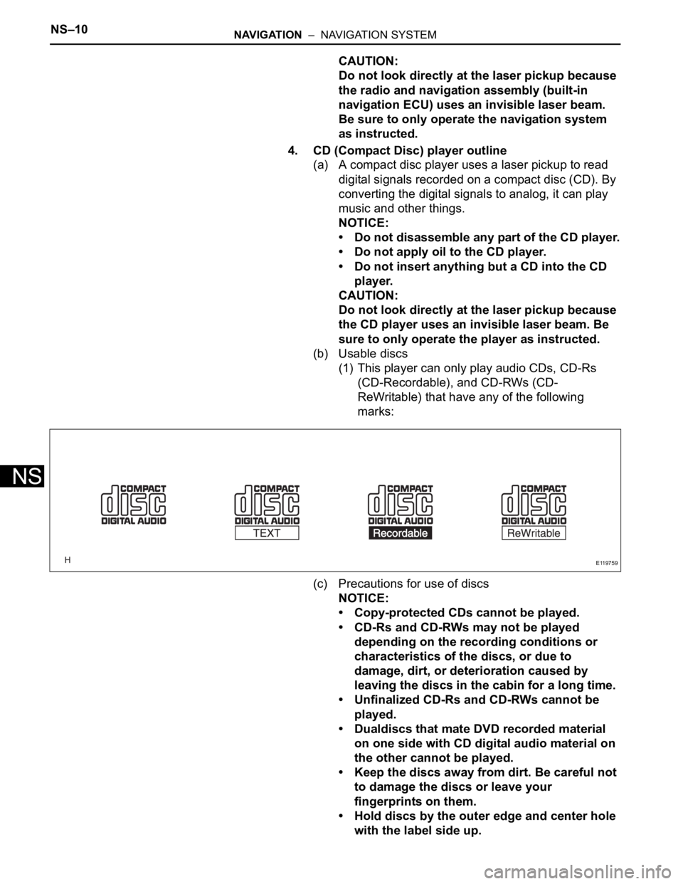
(b) Usable discs
(1) This player can only play audio CDs, CD-Rs
(CD-Recordable), and CD-RWs (CD-
ReWritable) that have any of the following
marks:
(c) Precautions for use of discs
NOTICE:
• Copy-protected CDs cannot be played.
• CD-Rs and CD-RWs may not be played
depending on the recording conditions or
characteristics of the discs, or due to
damage, dirt, or deterioration caused by
leaving the discs in the cabin for a long time.
• Unfinalized CD-Rs and CD-RWs cannot be
played.
• Dualdiscs that mate DVD recorded material
on one side with CD digital audio material on
the other cannot be played.
• Keep the discs away from dirt. Be careful not
to damage the discs or leave your
fingerprints on them.
• Hold discs by the outer edge and center hole
with the label side up.
E119759
Page 278 of 3000
PM–4PARK ASSIST / MONITORING – REAR VIEW MONITOR SYSTEM
PM
(b) Images are difficult to discern even in normal
conditions if:
(1) Camera screen is frosted over (the image
immediately after turning the ignition switch to
the on position may be blurred or darker than
normal).
(2) A strong beam of light, such as a sunbeam or
headlight, hits the camera.
(3) It is too dark around the camera (at night, etc.).
(4) The ambient temperature around the camera is
either too high or too low.
HINT:
When a strong light, such as a sunbeam
reflected off the vehicle's body, hits the camera,
the image may be blurred. This is called the
"SMEAR" phenomenon, peculiar to the CCD
camera.
Page 299 of 3000
SEAT – FRONT POWER SEAT CONTROL SYSTEMSE–7
SE
1. SIGNAL COMMUNICATION TABLE
Driver Side Power Seat (with Memory)
B168179E01
Transmitting ECU
(Transmitter)Receiving ECU Signals Communication method
ECMPower seat control switch and
ECUShift position P signal CAN - BEAN
Outer mirror control ECU LHPower seat control switch and
ECUSeat memory switch signal BEAN
Power seat control switch and
ECUOuter mirror control ECU LH• M1 switch memory command
signal
• M2 switch memory command
signal
• M1 switch regeneration
command signal
• M2 switch regeneration
command signalBEAN