Page 182 of 3000

BC–6BRAKE CONTROL – ANTI-LOCK BRAKE SYSTEM
BC
HINT:
The codes in this table are output only in Test Mode
(signal check).
4. SPEED SENSOR SIGNAL CHECK (WHEN USING
INTELLIGENT TESTER):
HINT:
• If the ignition switch is turned from the ON to the ACC
or LOCK position during Test Mode, DTCs of the
signal check function will be erased.
• During Test Mode, the ECU records all DTCs of the
signal check function. By performing the signal check,
the codes are erased if normality is confirmed. The
remaining codes are the codes where an abnormality
was found.
(a) Turn the ignition switch off.
(b) Check that the steering wheel is in the straight-
ahead position.
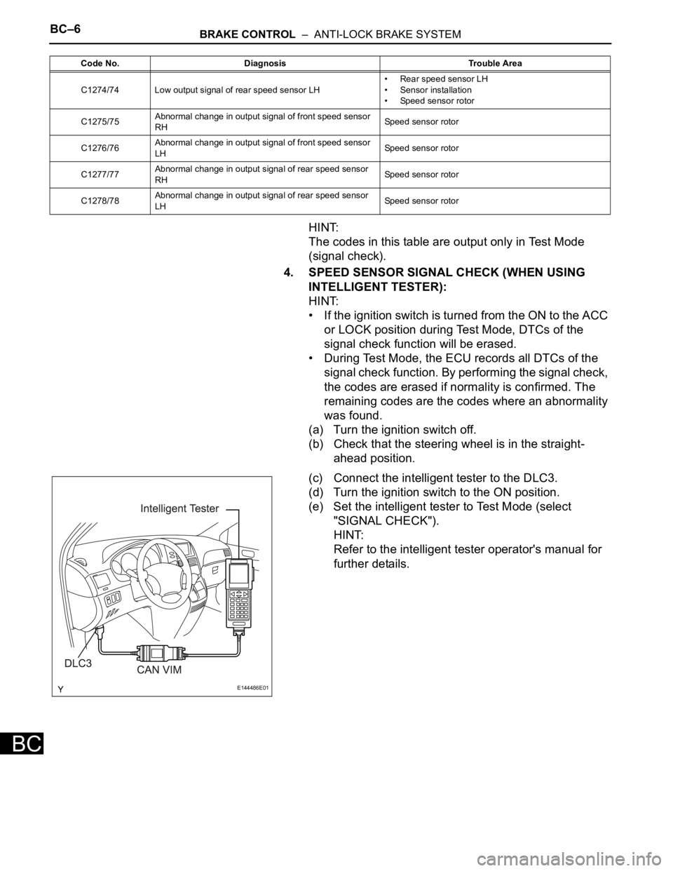
(c) Connect the intelligent tester to the DLC3.
(d) Turn the ignition switch to the ON position.
(e) Set the intelligent tester to Test Mode (select
"SIGNAL CHECK").
HINT:
Refer to the intelligent tester operator's manual for
further details.
C1274/74 Low output signal of rear speed sensor LH• Rear speed sensor LH
• Sensor installation
• Speed sensor rotor
C1275/75Abnormal change in output signal of front speed sensor
RHSpeed sensor rotor
C1276/76Abnormal change in output signal of front speed sensor
LHSpeed sensor rotor
C1277/77Abnormal change in output signal of rear speed sensor
RHSpeed sensor rotor
C1278/78Abnormal change in output signal of rear speed sensor
LHSpeed sensor rotor Code No. Diagnosis Trouble Area
E144486E01
Page 207 of 3000

AIR CONDITIONING – CONDENSERAC–237
AC
REMOVAL
1. RECOVER REFRIGERANT FROM REFRIGERATION
SYSTEM (See page AC-172)
2. REMOVE NO. 2 AIR CLEANER INLET (See page EM-
28)
3. REMOVE FRONT BUMPER ASSEMBLY (See page
ET-3)
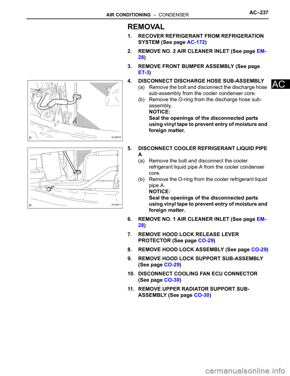
4. DISCONNECT DISCHARGE HOSE SUB-ASSEMBLY
(a) Remove the bolt and disconnect the discharge hose
sub-assembly from the cooler condenser core.
(b) Remove the O-ring from the discharge hose sub-
assembly.
NOTICE:
Seal the openings of the disconnected parts
using vinyl tape to prevent entry of moisture and
foreign matter.
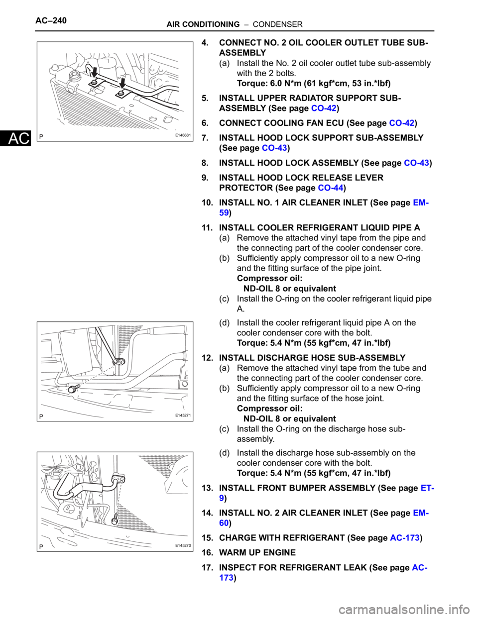
5. DISCONNECT COOLER REFRIGERANT LIQUID PIPE
A
(a) Remove the bolt and disconnect the cooler
refrigerant liquid pipe A from the cooler condenser
core.
(b) Remove the O-ring from the cooler refrigerant liquid
pipe A.
NOTICE:
Seal the openings of the disconnected parts
using vinyl tape to prevent entry of moisture and
foreign matter.
6. REMOVE NO. 1 AIR CLEANER INLET (See page EM-
28)
7. REMOVE HOOD LOCK RELEASE LEVER
PROTECTOR (See page CO-29)
8. REMOVE HOOD LOCK ASSEMBLY (See page CO-29)
9. REMOVE HOOD LOCK SUPPORT SUB-ASSEMBLY
(See page CO-29)
10. DISCONNECT COOLING FAN ECU CONNECTOR
(See page CO-30)
11. REMOVE UPPER RADIATOR SUPPORT SUB-
ASSEMBLY (See page CO-30)
E145270
E145271
Page 210 of 3000

AC–240AIR CONDITIONING – CONDENSER
AC
4. CONNECT NO. 2 OIL COOLER OUTLET TUBE SUB-
ASSEMBLY
(a) Install the No. 2 oil cooler outlet tube sub-assembly
with the 2 bolts.
Torque: 6.0 N*m (61 kgf*cm, 53 in.*lbf)
5. INSTALL UPPER RADIATOR SUPPORT SUB-
ASSEMBLY (See page CO-42)
6. CONNECT COOLING FAN ECU (See page CO-42)
7. INSTALL HOOD LOCK SUPPORT SUB-ASSEMBLY
(See page CO-43)
8. INSTALL HOOD LOCK ASSEMBLY (See page CO-43)
9. INSTALL HOOD LOCK RELEASE LEVER
PROTECTOR (See page CO-44)
10. INSTALL NO. 1 AIR CLEANER INLET (See page EM-
59)
11. INSTALL COOLER REFRIGERANT LIQUID PIPE A
(a) Remove the attached vinyl tape from the pipe and
the connecting part of the cooler condenser core.
(b) Sufficiently apply compressor oil to a new O-ring
and the fitting surface of the pipe joint.
Compressor oil:
ND-OIL 8 or equivalent
(c) Install the O-ring on the cooler refrigerant liquid pipe
A.
(d) Install the cooler refrigerant liquid pipe A on the
cooler condenser core with the bolt.
Torque: 5.4 N*m (55 kgf*cm, 47 in.*lbf)
12. INSTALL DISCHARGE HOSE SUB-ASSEMBLY
(a) Remove the attached vinyl tape from the tube and
the connecting part of the cooler condenser core.
(b) Sufficiently apply compressor oil to a new O-ring
and the fitting surface of the hose joint.
Compressor oil:
ND-OIL 8 or equivalent
(c) Install the O-ring on the discharge hose sub-
assembly.
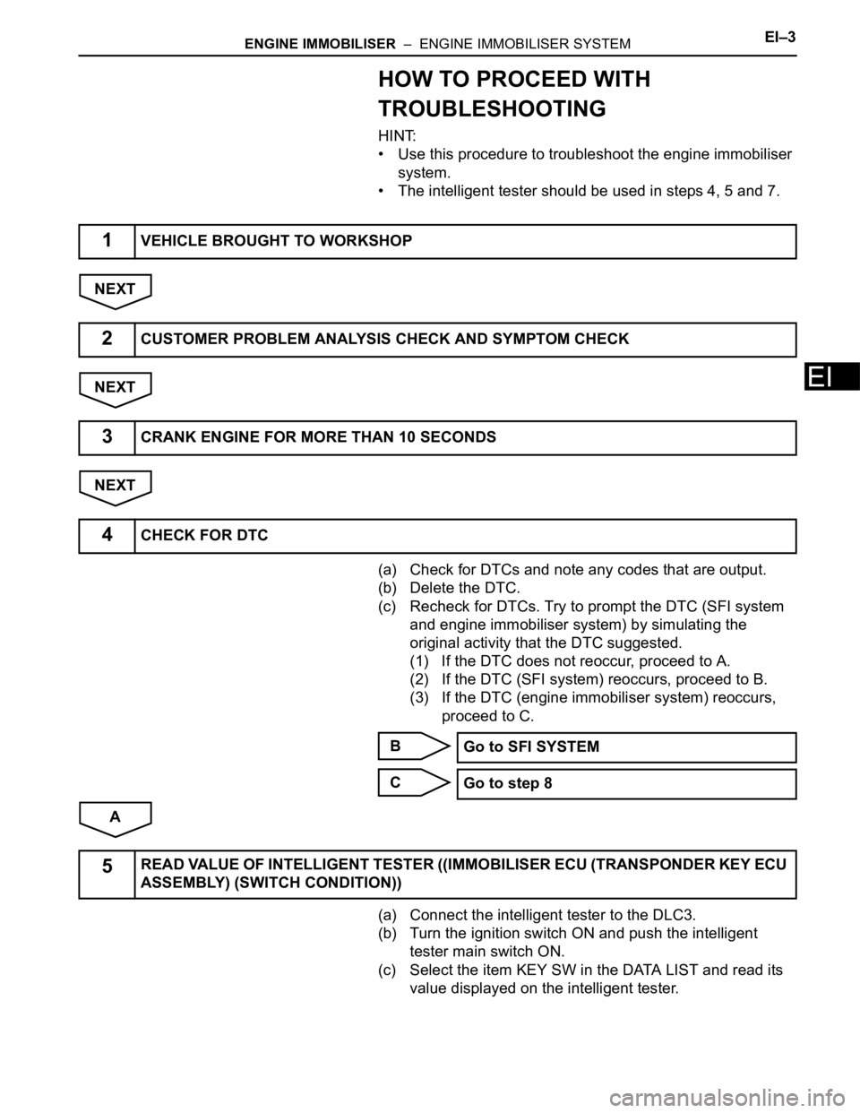
(d) Install the discharge hose sub-assembly on the
cooler condenser core with the bolt.
Torque: 5.4 N*m (55 kgf*cm, 47 in.*lbf)
13. INSTALL FRONT BUMPER ASSEMBLY (See page ET-
9)
14. INSTALL NO. 2 AIR CLEANER INLET (See page EM-
60)
15. CHARGE WITH REFRIGERANT (See page AC-173)
16. WARM UP ENGINE
17. INSPECT FOR REFRIGERANT LEAK (See page AC-
173)
E146681
E145271
E145270
Page 236 of 3000

THEFT DETERRENT – THEFT DETERRENT SYSTEMTD–3
TD
SYSTEM DESCRIPTION
1. OUTLINE OF THEFT DETERRENT SYSTEM
(a) When the theft deterrent system detects that the
vehicle is being tampered with, the system sets off
the alarm, causing the horns to sound and the lights
to light up or blink in order to alert people around the
vehicle to the theft.
(b) The theft deterrent system has 2 modes; one is the
active arming mode (see ACTIVE ARMING MODE)
and the other is passive arming mode (see
PASSIVE ARMING MODE). The passive arming
mode can be switched ON/OFF using the specified
method.
(c) Each mode has 4 states; a disarmed state, an
arming preparation state, an armed state and an
alarm sounding state.
(1) Disarmed state:
• The alarm function is not operating.
• The theft deterrent system is not operating.
(2) Arming preparation state:
• The time until the system goes into the armed
state.
• The theft deterrent system is not operating.
(3) Armed state:
• The theft deterrent system is operating.
(4) Alarm sounding state:
• Alarm function is operating.
Alarm time:
Approx. 60 sec.
Refer to table below for alarm method and time:
HINT:
If any of the doors are unlocked with no key in
the ignition key cylinder during the armed state,
a forced door lock signal will be output (see
FORCED DOOR LOCK CONTROL).
2. ACTIVE ARMING MODE
HINT:
• Active arming mode starts the alarm control
immediately after the doors are locked.
• This system activates as described in the diagram
below when one of items for each condition is met.
Alarm MethodHeadlight Blinking (approx. 0.4 second cycles)
Taillight Blinking (approx. 0.4 second cycles)
Hazard Warning Light Blinking (cycles of flasher relay)
Interior Light Illuminating
Vehicle HornSounding
(approx. 0.4 second cycles)
Security HornSounding
(approx. 0.4 second cycles)
Alarm Time Approx. 60 sec.
Page 242 of 3000

THEFT DETERRENT – THEFT DETERRENT SYSTEMTD–9
TD
• The theft deterrent system switches to the
alarm sounding state. Under this condition,
the theft deterrent system is controlling the
alarm rather than the panic alarm control. In
order to cancel this alarm, refer to the theft
deterrent system alarm sounding state
cancellation procedure. (This condition is
common both to active arming mode to
passive arming mode.)
HINT:
Active arming mode: See ACTIVE ARMING
MODE.
Passive arming mode: See PASSIVE ARMING
MODE.
7. SECURITY INDICATOR OUTPUT
(a) The multiplex network body ECU outputs a signal to
light up the security indicator, according to the state
of the theft deterrent system. However, some of the
actual lighting conditions of the security indicator
are different from the output signals of the multiplex
network body ECU.
Output:
Blinking cycle:
HINT:
• *: The above condition is common both to active
arming mode and to passive arming mode.
• When the immobiliser system is set, the security
indicator blinks during both the disarmed state
and the armed state, due to the output signals
from the immobiliser system.
State of Theft Deterrent System*Security Indicator
Output Signals from Body ECU Actual Lighting Condition
Disarmed state (1), (2) OFFOFF (Immobiliser system unset)
BLINKING (Immobiliser system set)
Arming preparation state ON ON
Armed state OFF BLINKING
Alarm sounding state ON ON
Time Security Indicator
0.2 sec. ON
1.8 sec. OFF
Page 243 of 3000

ENGINE IMMOBILISER – ENGINE IMMOBILISER SYSTEMEI–3
EI
HOW TO PROCEED WITH
TROUBLESHOOTING
HINT:
• Use this procedure to troubleshoot the engine immobiliser
system.
• The intelligent tester should be used in steps 4, 5 and 7.
NEXT
NEXT
NEXT
(a) Check for DTCs and note any codes that are output.
(b) Delete the DTC.
(c) Recheck for DTCs. Try to prompt the DTC (SFI system
and engine immobiliser system) by simulating the
original activity that the DTC suggested.
(1) If the DTC does not reoccur, proceed to A.
(2) If the DTC (SFI system) reoccurs, proceed to B.
(3) If the DTC (engine immobiliser system) reoccurs,
proceed to C.
B
C
A
(a) Connect the intelligent tester to the DLC3.
(b) Turn the ignition switch ON and push the intelligent
tester main switch ON.
(c) Select the item KEY SW in the DATA LIST and read its
value displayed on the intelligent tester.
1VEHICLE BROUGHT TO WORKSHOP
2CUSTOMER PROBLEM ANALYSIS CHECK AND SYMPTOM CHECK
3CRANK ENGINE FOR MORE THAN 10 SECONDS
4CHECK FOR DTC
Go to SFI SYSTEM
Go to step 8
5READ VALUE OF INTELLIGENT TESTER ((IMMOBILISER ECU (TRANSPONDER KEY ECU
ASSEMBLY) (SWITCH CONDITION))
Page 244 of 3000
EI–4ENGINE IMMOBILISER – ENGINE IMMOBILISER SYSTEM
EI
Transponder key ECU
NG
OK
(a) If the fault is not listed on the problem symptoms table,
proceed to A.
(b) If the fault is listed on the problem symptoms table,
proceed to B.
B
A
(a) Inspection with the intelligent tester (ECU DATA
MONITOR).
(b) Inspection with the intelligent tester (ACTIVE TEST).
(c) Terminals of ECU (See page EI-10).
NEXT
NEXT
NEXT
ItemMeasurement Item / Display
(Range)Normal Condition Diagnostic Note
KEY SWUnlock warning switch signal /
ON or OFFON: Key is in ignition key
cylinder
OFF: No key is in ignition key
cylinder-
Go to DTC B2780
6PROBLEM SYMPTOMS TABLE
Go to step 8
7OVERALL ANALYSIS AND TROUBLESHOOTING
8ADJUST, REPAIR OR REPLACE
9CONFIRMATION TEST
END
Page 245 of 3000
CRUISE CONTROL – CRUISE CONTROL SYSTEMCC–3
CC
SYSTEM DIAGRAM
Communication Table:
Sender Receiver Signal Line
ECM Gateway ECUCRUISE main indicator operation
signalCAN
E144498E02