Page 382 of 3000

ES–762GR-FE ENGINE CONTROL SYSTEM – SFI SYSTEM
ES
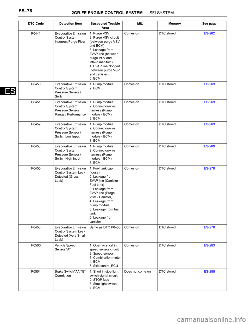
P0441 Evaporative Emission
Control System
Incorrect Purge Flow1. Purge VSV
2. Purge VSV circuit
(between purge VSV
and ECM)
3. Leakage from
EVAP line (between
purge VSV and
intake manifold)
4. EVAP line clogged
(between purge VSV
and canister)
5. ECMComes on DTC storedES-262
P0450 Evaporative Emission
Control System
Pressure Sensor /
Switch1. Pump module
2. ECMComes on DTC storedES-269
P0451 Evaporative Emission
Control System
Pressure Sensor
Range / Performance1. Pump module
2. Connector/wire
harness (Pump
module - ECM)
3. ECMComes on DTC storedES-269
P0452 Evaporative Emission
Control System
Pressure Sensor /
Switch Low Input1. Pump module
2. Connector/wire
harness (Pump
module - ECM)
3. ECMComes on DTC storedES-269
P0453 Evaporative Emission
Control System
Pressure Sensor /
Switch High Input1. Pump module
2. Connector/wire
harness (Pump
module - ECM)
3. ECMComes on DTC storedES-269
P0455 Evaporative Emission
Control System Leak
Detected (Gross
Leak)1. Fuel tank cap
(loose)
2. Leakage from
EVAP line (Canister -
Fuel tank)
3. Leakage from
EVAP line (Purge
VSV - Canister)
4. Leakage from
pump module
5. Leakage from fuel
tank
6. Leakage from
canisterComes on DTC storedES-278
P0456 Evaporative Emission
Control System Leak
Detected (Very Small
Leak)Same as DTC P0455 Comes on DTC storedES-278
P0500 Vehicle Speed
Sensor "A"1. Open or short in
speed sensor circuit
2. Speed sensor
3. Combination meter
4. ECM
5. Skid control ECUComes on DTC storedES-283
P0504 Brake Switch "A" / "B"
Correlation1. Short in stop light
switch signal circuit
2. STOP fuse
3. Stop light switch
4. ECMDoes not come on DTC storedES-288 DTC Code Detection Item Suspected Trouble
AreaMIL Memory See page
Page 397 of 3000
2GR-FE ENGINE CONTROL SYSTEM – SFI SYSTEMES–91
ES
(a) Connect the intelligent tester to the DLC3.
(b) Turn the ignition switch to the ON position and turn the
tester on.
(c) Clear the DTCs (See page ES-39).
(d) Start the engine and warm it up.
(e) Select the check mode using the tester (See page ES-
43).
(f) Drive the vehicle for more than 10 minutes.
(g) Read the DTCs using the tester.
OK:
No DTC outputs.
NG
OK
3CHECK WHETHER DTC OUTPUT RECURS (DTC P0011, P0012, P0021 OR P0022)
Go to step 4
SYSTEM IS OK
Page 399 of 3000
2GR-FE ENGINE CONTROL SYSTEM – SFI SYSTEMES–93
ES
(c) Apply the positive battery voltage to terminal 1 and the
negative battery voltage to terminal 2. Check the valve
operation.
OK:
Valve moves quickly.
(d) Reinstall the OCV.
NG
OK
(a) Remove the oil pipe No. 1 or oil pipe assembly.
(b) Remove the oil control valve filter.
(c) Check that the filter and pipe are not clogged.
OK:
The filter and pipe are not clogged.
NG
OK
NEXT
(a) Connect the intelligent tester to the DLC3.
(b) Turn the ignition switch to the ON position and turn the
tester on.
(c) Clear the DTCs (See page ES-39).
(d) Start the engine and warm it up.
(e) Select the check mode using the tester (See page ES-
43).
A097066E08
REPLACE CAMSHAFT TIMING OIL
CONTROL VALVE ASSEMBLY (See page ES-
486)
6CHECK OIL PIPE AND OIL CONTROL VALVE FILTER
G042497E01
CLEAN OIL CONTROL VALVE FILTER AND
PIPE
7REPLACE CAMSHAFT TIMING GEAR ASSEMBLY
8CHECK WHETHER DTC OUTPUT RECURS
Page 408 of 3000

ES–1022GR-FE ENGINE CONTROL SYSTEM – SFI SYSTEM
ES
• Read freeze frame data using the intelligent tester. The ECM records vehicle and driving condition
information as freeze frame data the moment a DTC is stored. When troubleshooting, freeze frame
data can be helpful in determining whether the vehicle was running or stopped, whether the engine
was warmed up or not, whether the air-fuel ratio was lean or rich, as well as other data recorded at the
time of a malfunction.
(a) Connect the intelligent tester to the DLC3.
(b) Turn the ignition switch to the ON position and turn the
tester on.
(c) Select the following menu items: DIAGNOSIS /
ENHANCED OBD II / DTC INFO / CURRENT CODES.
(d) Read the DTCs.
Result
HINT:
If any DTCs other than P0014, P0015, P0024 or P0025
are output, troubleshoot those DTCs first.
B
A
(a) Connect the intelligent tester to the DLC3.
(b) Start the engine and turn the tester on.
(c) Warm up the engine.
(d) Select the following menu items on the tester:
DIAGNOSIS / ENHANCED OBD II / ACTIVE TEST /
VVT EX B1 or VVT EX B2.
(e) Check the engine speed while operating the Oil Control
Valve (OCV) using the tester.
OK
NG
OK
(a) Connect the intelligent tester to the DLC3.
(b) Turn the ignition switch to the ON position and turn the
tester on.
(c) Clear the DTCs (See page ES-39).
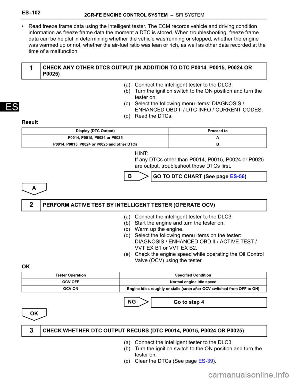
1CHECK ANY OTHER DTCS OUTPUT (IN ADDITION TO DTC P0014, P0015, P0024 OR
P0025)
Display (DTC Output) Proceed to
P0014, P0015, P0024 or P0025 A
P0014, P0015, P0024 or P0025 and other DTCs B
GO TO DTC CHART (See page ES-56)
2PERFORM ACTIVE TEST BY INTELLIGENT TESTER (OPERATE OCV)
Tester Operation Specified Condition
OCV OFF Normal engine idle speed
OCV ON Engine idles roughly or stalls (soon after OCV switched from OFF to ON)
Go to step 4
3CHECK WHETHER DTC OUTPUT RECURS (DTC P0014, P0015, P0024 OR P0025)
Page 411 of 3000
2GR-FE ENGINE CONTROL SYSTEM – SFI SYSTEMES–105
ES
OK
NEXT
(a) Connect the intelligent tester to the DLC3.
(b) Turn the ignition switch to the ON position and turn the
tester on.
(c) Clear the DTCs (See page ES-39).
(d) Start the engine and warm it up.
(e) Select the check mode using the tester (See page ES-
43).
(f) Drive the vehicle for more than 10 minutes.
(g) Confirm that no DTC is set using the tester.
OK:
No DTC output.
HINT:
DTC P0014, P0015, P0024 or P0025 is output when
foreign objects in engine oil are caught in some parts of
the system. These codes will stay registered even if the
system returns to normal after a short time. These
foreign objects are then captured by the oil filter, thus
eliminating the source of the problem.
NG
OK
7REPLACE CAMSHAFT TIMING GEAR ASSEMBLY
8CHECK WHETHER DTC OUTPUT RECURS
REPLACE ECM (See page ES-498)
SYSTEM IS OK
Page 413 of 3000

2GR-FE ENGINE CONTROL SYSTEM – SFI SYSTEMES–107
ES
MONITOR STRATEGY
TYPICAL ENABLING CONDITIONS
All:
P0016 and P0018:
P0017 and P0019:
TYPICAL MALFUNCTION THRESHOLDS
P0016 and P0018:
P0017 and P0019:
WIRING DIAGRAM
Refer to DTC P0335 (See page ES-222).
INSPECTION PROCEDURE
HINT:
Read freeze frame data using the intelligent tester. The ECM records vehicle and driving condition
information as freeze frame data the moment a DTC is stored. When troubleshooting, freeze frame data
can be helpful in determining whether the vehicle was running or stopped, whether the engine was
warmed up or not, whether the air-fuel ratio was lean or rich, as well as other data recorded at the time of
a malfunction.
Related DTCsP0016: Deviation in crankshaft position sensor signal and camshaft position sensor
signal (Bank 1)
P0017: Deviation in crankshaft position sensor signal and camshaft position sensor
signal (Bank 1 Sensor 2)
P0018: Deviation in crankshaft position sensor signal and camshaft position sensor
signal (Bank 2)
P0019: Deviation in crankshaft position sensor signal and camshaft position sensor
signal (Bank 2 Sensor 2)
Required Sensors / Components (Main)P0016 and P0018: VVT actuator
P0017 and P0019: Timing chain/belt
Required Sensors / Components (Related)P0016 and P0018: Camshaft position sensor, Crankshaft position sensor
P0017 and P0019: None
Frequency of Operation Once per driving cycle
Duration Less than 60 seconds
MIL Operation 2 driving cycles
Sequence of Operation None
The monitor will run whenever these DTCs are not
presentP0011, P0012 (VVT System 1-Advance, Retard), P0021, P0022 (VVT System 2-
Adavance, Retard), P0115, P0116, P0117, P0118 (ECT Sensor)
Engine RPM 500 to 1000 rpm
VVT feedback mode Executing
VVT Maximum advanced position
Engine RPM 500 to 1000 rpm
One of the following conditions is met: Condition 1 or 2
1. VVT learning value at maximum retarded valve
timingLess than 18.5
CA
2. VVT learning value at maximum retarded valve
timingMore than 43.5
CA
One of the following conditions is met: Condition 1 or 2
1. VVT learning value Less than 77
CA
2. VVT learning value More than 102
CA
Page 414 of 3000

ES–1082GR-FE ENGINE CONTROL SYSTEM – SFI SYSTEM
ES
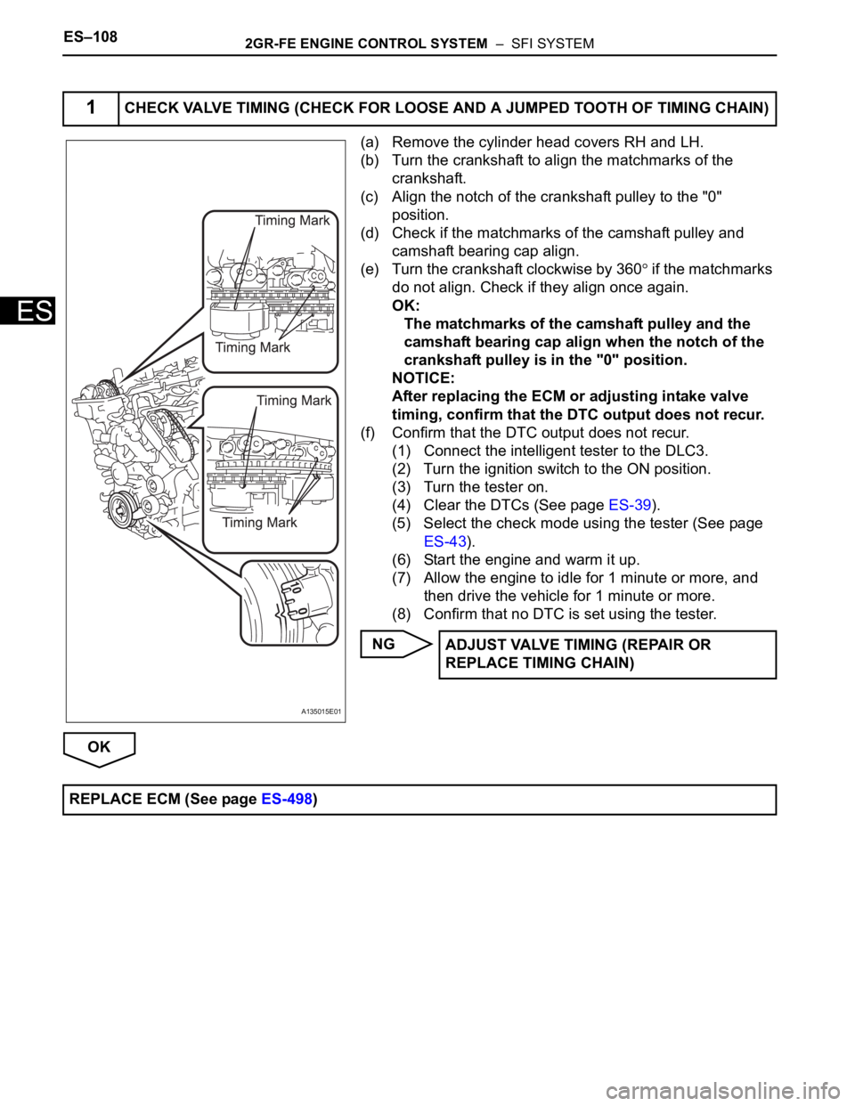
(a) Remove the cylinder head covers RH and LH.
(b) Turn the crankshaft to align the matchmarks of the
crankshaft.
(c) Align the notch of the crankshaft pulley to the "0"
position.
(d) Check if the matchmarks of the camshaft pulley and
camshaft bearing cap align.
(e) Turn the crankshaft clockwise by 360
if the matchmarks
do not align. Check if they align once again.
OK:
The matchmarks of the camshaft pulley and the
camshaft bearing cap align when the notch of the
crankshaft pulley is in the "0" position.
NOTICE:
After replacing the ECM or adjusting intake valve
timing, confirm that the DTC output does not recur.
(f) Confirm that the DTC output does not recur.
(1) Connect the intelligent tester to the DLC3.
(2) Turn the ignition switch to the ON position.
(3) Turn the tester on.
(4) Clear the DTCs (See page ES-39).
(5) Select the check mode using the tester (See page
ES-43).
(6) Start the engine and warm it up.
(7) Allow the engine to idle for 1 minute or more, and
then drive the vehicle for 1 minute or more.
(8) Confirm that no DTC is set using the tester.
NG
OK
1CHECK VALVE TIMING (CHECK FOR LOOSE AND A JUMPED TOOTH OF TIMING CHAIN)
A135015E01
ADJUST VALVE TIMING (REPAIR OR
REPLACE TIMING CHAIN)
REPLACE ECM (See page ES-498)
Page 421 of 3000

2GR-FE ENGINE CONTROL SYSTEM – SFI SYSTEMES–115
ES
OK
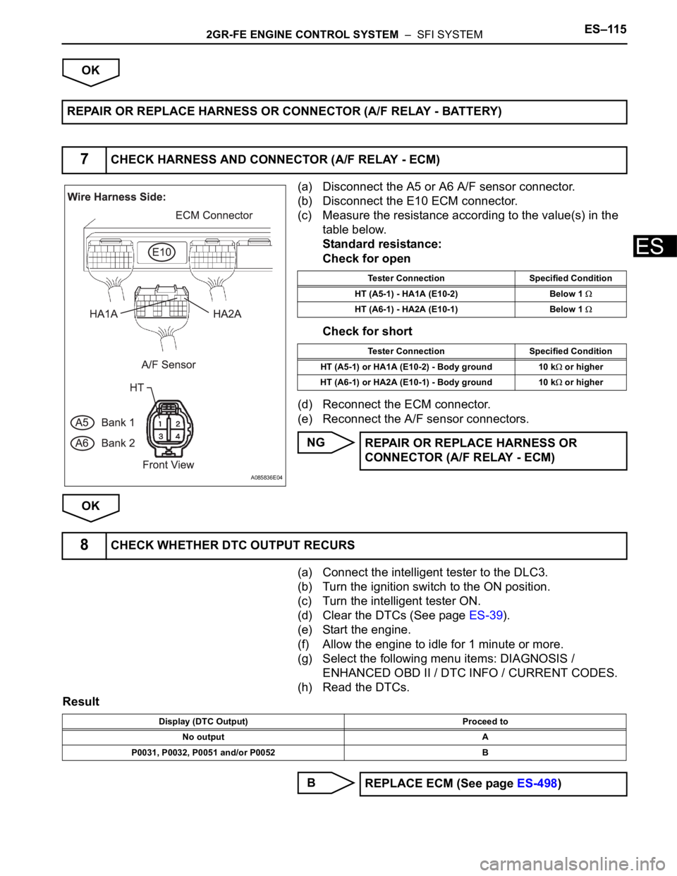
(a) Disconnect the A5 or A6 A/F sensor connector.
(b) Disconnect the E10 ECM connector.
(c) Measure the resistance according to the value(s) in the
table below.
Standard resistance:
Check for open
Check for short
(d) Reconnect the ECM connector.
(e) Reconnect the A/F sensor connectors.
NG
OK
(a) Connect the intelligent tester to the DLC3.
(b) Turn the ignition switch to the ON position.
(c) Turn the intelligent tester ON.
(d) Clear the DTCs (See page ES-39).
(e) Start the engine.
(f) Allow the engine to idle for 1 minute or more.
(g) Select the following menu items: DIAGNOSIS /
ENHANCED OBD II / DTC INFO / CURRENT CODES.
(h) Read the DTCs.
Result
B REPAIR OR REPLACE HARNESS OR CONNECTOR (A/F RELAY - BATTERY)
7CHECK HARNESS AND CONNECTOR (A/F RELAY - ECM)
A085836E04
Tester Connection Specified Condition
HT (A5-1) - HA1A (E10-2) Below 1
HT (A6-1) - HA2A (E10-1) Below 1
Tester Connection Specified Condition
HT (A5-1) or HA1A (E10-2) - Body ground 10 k
or higher
HT (A6-1) or HA2A (E10-1) - Body ground 10 k
or higher
REPAIR OR REPLACE HARNESS OR
CONNECTOR (A/F RELAY - ECM)
8CHECK WHETHER DTC OUTPUT RECURS
Display (DTC Output) Proceed to
No output A
P0031, P0032, P0051 and/or P0052 B
REPLACE ECM (See page ES-498)