Page 662 of 3000

2GR-FE ENGINE CONTROL SYSTEM – SFI SYSTEMES–369
ES
9. Drive the vehicle at a proper vehicle speed to perform fuel-cut operation (refer to the following HINT)
(Procedure "D").
HINT:
Fuel-cut is performed when the following conditions are met:
• Accelerator pedal is fully released.
• Engine speed is 2500 rpm or more (fuel injection resumes at 1000 rpm).
10. Accelerate the vehicle to 40 mph (64 km/h) or more by depressing the accelerator pedal for at least 10
seconds (Procedure "E").
11. Soon after performing procedure "J" on the previous page, release the accelerator pedal for at least 4
seconds without depressing the brake pedal, in order to execute fuel-cut control (Procedure "F").
12. Allow the vehicle to decelerate until the vehicle speed declines to less than 6 mph (10 km/h).
13. Repeat procedures from "H" through "K" in this section at least 3 times per driving cycle.
HINT:
Completion of all A/F sensor monitors is required to change the value in TEST RESULT.
CAUTION:
Strictly observe posted speed limits, traffic laws, and road conditions when performing these
driving patterns.
INSPECTION PROCEDURE
HINT:
Malfunctioning areas can be identified by performing the A/F CONTROL function provided in the ACTIVE
TEST. The A/F CONTROL function can help to determine whether the Air-Fuel Ratio (A/F) sensor, Heated
Oxygen (HO2) sensor and other potential trouble areas are malfunctioning.
The following instructions describe how to conduct the A/F CONTROL operation using an intelligent
tester.
(a) Connect the intelligent tester to the DLC3.
(b) Start the engine and turn the tester on.
(c) Warm up the engine at an engine speed of 2500 rpm for approximately 90 seconds.
(d) Select the following menu items on the tester: DIAGNOSIS / ENHANCED OBD II / ACTIVE TEST / A/
F CONTROL.
(e) Perform the A/F CONTROL operation with the engine in an idling condition (press the RIGHT or LEFT
button to change the fuel injection volume).
(f) Monitor the voltage outputs of the A/F and HO2 sensors (AFS B1S1 and O2S B1S2 or AFS B2S1 and
O2S B2S2) displayed on the tester.
HINT:
• The A/F CONTROL operation lowers the fuel injection volume by 12.5% or increases the injection
volume by 25%.
• Each sensor reacts in accordance with increases and decreases in the fuel injection volume.
Standard voltage
NOTICE:
The Air-Fuel Ratio (A/F) sensor has an output delay of a few seconds and the Heated Oxygen
(HO2) sensor has a maximum output delay of approximately 20 seconds.
Tester Display (Sensor) Injection Volumes Status Voltages
AFS B1S1 or AFS B2S1 (A/F) +25% Rich Less than 3.0
AFS B1S1 or AFS B2S1 (A/F) -12.5% Lean More than 3.35
O2S B1S2 or O2S B2S2 (HO2) +25% Rich More than 0.55
O2S B1S2 or O2S B2S2 (HO2) -12.5% Lean Less than 0.4
Page 667 of 3000

ES–3742GR-FE ENGINE CONTROL SYSTEM – SFI SYSTEM
ES
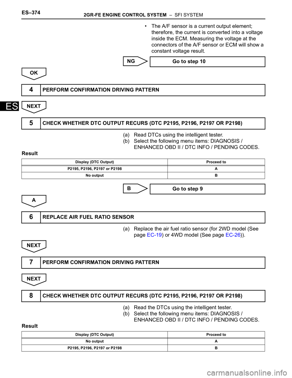
• The A/F sensor is a current output element;
therefore, the current is converted into a voltage
inside the ECM. Measuring the voltage at the
connectors of the A/F sensor or ECM will show a
constant voltage result.
NG
OK
NEXT
(a) Read DTCs using the intelligent tester.
(b) Select the following menu items: DIAGNOSIS /
ENHANCED OBD II / DTC INFO / PENDING CODES.
Result
B
A
(a) Replace the air fuel ratio sensor (for 2WD model (See
page EC-19) or 4WD model (See page EC-26)).
NEXT
NEXT
(a) Read the DTCs using the intelligent tester.
(b) Select the following menu items: DIAGNOSIS /
ENHANCED OBD II / DTC INFO / PENDING CODES.
Result Go to step 10
4PERFORM CONFIRMATION DRIVING PATTERN
5CHECK WHETHER DTC OUTPUT RECURS (DTC P2195, P2196, P2197 OR P2198)
Display (DTC Output) Proceed to
P2195, P2196, P2197 or P2198 A
No output B
Go to step 9
6REPLACE AIR FUEL RATIO SENSOR
7PERFORM CONFIRMATION DRIVING PATTERN
8CHECK WHETHER DTC OUTPUT RECURS (DTC P2195, P2196, P2197 OR P2198)
Display (DTC Output) Proceed to
No output A
P2195, P2196, P2197 or P2198 B
Page 671 of 3000
ES–3782GR-FE ENGINE CONTROL SYSTEM – SFI SYSTEM
ES
NG
OK
(a) Replace the air fuel ratio sensor (for 2WD model (See
page EC-19) or 4WD model (See page EC-26)).
NEXT
NEXT
(a) Read the DTCs using the intelligent tester.
(b) Select the following menu items: DIAGNOSIS /
ENHANCED OBD II / DTC INFO / PENDING CODES.
Result
B
A
(a) Has the vehicle run out of fuel in the past?.
NO
YES
(a) Replace the air fuel ratio sensor (for 2WD model (See
page EC-19) or 4WD model (See page EC-26)).
NEXTREPLACE FUEL INJECTOR ASSEMBLY (See
page FU-13)
16REPLACE AIR FUEL RATIO SENSOR
17PERFORM CONFIRMATION DRIVING PATTERN
18CHECK WHETHER DTC OUTPUT RECURS (DTC P2195, P2196, P2197 OR P2198)
Display (DTC Output) Proceed to
No output A
P2195, P2196, P2197 or P2198 B
REPLACE ECM AND PERFORM
CONFIRMATION DRIVING PATTERN
19CONFIRM WHETHER VEHICLE HAS RUN OUT OF FUEL IN PAST
CHECK FOR INTERMITTENT PROBLEMS
DTC CAUSED BY RUNNING OUT OF FUEL
20REPLACE AIR FUEL RATIO SENSOR
Page 672 of 3000
2GR-FE ENGINE CONTROL SYSTEM – SFI SYSTEMES–379
ES
NEXT
(a) Connect the intelligent tester to the DLC3.
(b) Turn the ignition switch to the ON position and turn the
tester on.
(c) Read the DTCs using the intelligent tester.
(d) Select the following menu items: DIAGNOSIS /
ENHANCED OBD II / DTC INFO / PENDING CODES.
Result
B
A
21PERFORM CONFIRMATION DRIVING PATTERN
22CHECK WHETHER DTC OUTPUT RECURS (DTC P2195, P2196, P2197 OR P2198)
Display (DTC Output) Proceed to
No output A
P2195, P2196, P2197 or P2198 (A/F sensor pending DTCs) B
REPLACE ECM (See page ES-498)
END
Page 686 of 3000

2GR-FE ENGINE CONTROL SYSTEM – SFI SYSTEMES–393
ES
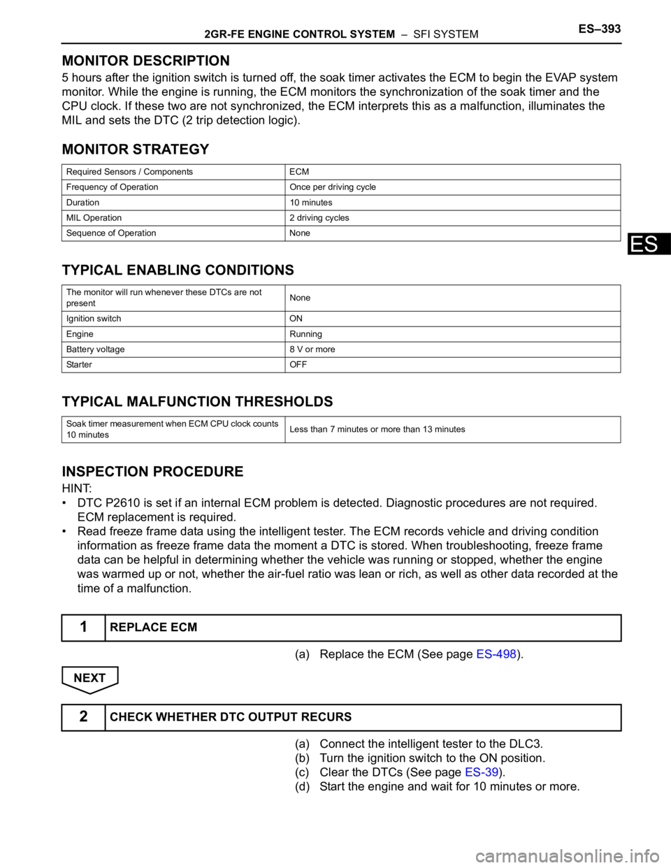
MONITOR DESCRIPTION
5 hours after the ignition switch is turned off, the soak timer activates the ECM to begin the EVAP system
monitor. While the engine is running, the ECM monitors the synchronization of the soak timer and the
CPU clock. If these two are not synchronized, the ECM interprets this as a malfunction, illuminates the
MIL and sets the DTC (2 trip detection logic).
MONITOR STRATEGY
TYPICAL ENABLING CONDITIONS
TYPICAL MALFUNCTION THRESHOLDS
INSPECTION PROCEDURE
HINT:
• DTC P2610 is set if an internal ECM problem is detected. Diagnostic procedures are not required.
ECM replacement is required.
• Read freeze frame data using the intelligent tester. The ECM records vehicle and driving condition
information as freeze frame data the moment a DTC is stored. When troubleshooting, freeze frame
data can be helpful in determining whether the vehicle was running or stopped, whether the engine
was warmed up or not, whether the air-fuel ratio was lean or rich, as well as other data recorded at the
time of a malfunction.
(a) Replace the ECM (See page ES-498).
NEXT
(a) Connect the intelligent tester to the DLC3.
(b) Turn the ignition switch to the ON position.
(c) Clear the DTCs (See page ES-39).
(d) Start the engine and wait for 10 minutes or more.
Required Sensors / Components ECM
Frequency of Operation Once per driving cycle
Duration 10 minutes
MIL Operation 2 driving cycles
Sequence of Operation None
The monitor will run whenever these DTCs are not
presentNone
Ignition switch ON
Engine Running
Battery voltage 8 V or more
Sta r t e r OF F
Soak timer measurement when ECM CPU clock counts
10 minutesLess than 7 minutes or more than 13 minutes
1REPLACE ECM
2CHECK WHETHER DTC OUTPUT RECURS
Page 696 of 3000
2GR-FE ENGINE CONTROL SYSTEM – SFI SYSTEMES–403
ES
NG
OK
NEXT
(a) Read the DTCs using the intelligent tester.
(b) Select the following menu items: DIAGNOSIS /
ENHANCED OBD II / DTC INFO / PENDING CODES.
Result
B
A
(a) Replace the air fuel ratio sensor (for 2WD model (See
page EC-19) or 4WD model (See page EC-26)).
A165205E01
REPAIR OR REPLACE HARNESS OR
CONNECTOR (A/F SENSOR - ECM)
4PERFORM CONFIRMATION DRIVING PATTERN
5CHECK WHETHER DTC OUTPUT RECURS (DTC P2A00 AND/OR P2A03)
Display (DTC Output) Proceed to
P2A00 and/or P2A03 A
No output B
CHECK FOR INTERMITTENT PROBLEMS
6REPLACE AIR FUEL RATIO SENSOR
Page 697 of 3000
ES–4042GR-FE ENGINE CONTROL SYSTEM – SFI SYSTEM
ES
NEXT
NEXT
(a) Read the DTCs using the intelligent tester.
(b) Select the following menu items: DIAGNOSIS /
ENHANCED OBD II / DTC INFO / PENDING CODES.
Result
B
A
7PERFORM CONFIRMATION DRIVING PATTERN
8CHECK WHETHER DTC OUTPUT RECURS (DTC P2A00 AND/OR P2A03)
Display (DTC Output) Proceed to
No output A
P2A00 and/or P2A03 B
REPLACE ECM
END
Page 801 of 3000
ES–5002GR-FE ENGINE CONTROL SYSTEM – ECM
ES
2. INSTALL ECM (with 10 speakers system)
(a) Install the ECM and stereo components amplifier
with the 4 nuts.
Torque: 5.5 N*m (56 kgf*cm, 49 in.*lbf)
(b) Connect the 5 ECM connectors and 2 stereo
components amplifier connectors.
3. INSTALL NO. 2 INSTRUMENT PANEL BOX
(a) Install the No. 2 instrument panel box.
4. INSTALL GLOVE COMPARTMENT DOOR ASSEMBLY
(a) Install the glove compartment door sub-assembly
frontward to install it.
(b) Push the right side wall and then push the left wall
to install the stoppers.
5. PERFORM REGISTRATION
(a) When replacing the ECM, perform distance control
ECU recognition in ECM (See page CC-125).
A162676
B066075E01
A162677
B066073E01