Page 975 of 3000
EM–1662GR-FE ENGINE MECHANICAL – ENGINE UNIT
EM
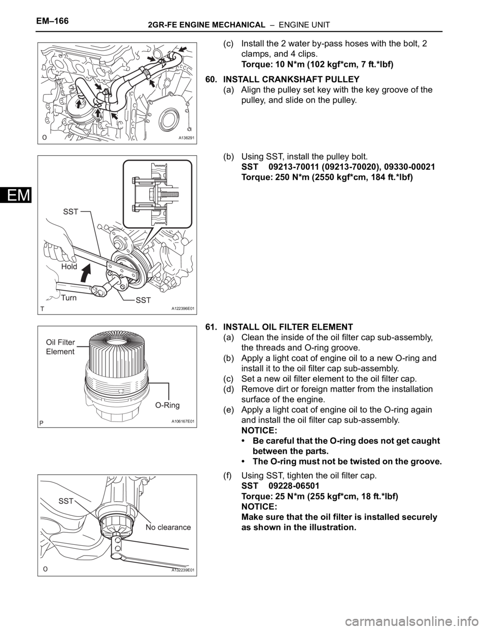
(c) Install the 2 water by-pass hoses with the bolt, 2
clamps, and 4 clips.
Torque: 10 N*m (102 kgf*cm, 7 ft.*lbf)
60. INSTALL CRANKSHAFT PULLEY
(a) Align the pulley set key with the key groove of the
pulley, and slide on the pulley.
(b) Using SST, install the pulley bolt.
SST 09213-70011 (09213-70020), 09330-00021
Torque: 250 N*m (2550 kgf*cm, 184 ft.*lbf)
61. INSTALL OIL FILTER ELEMENT
(a) Clean the inside of the oil filter cap sub-assembly,
the threads and O-ring groove.
(b) Apply a light coat of engine oil to a new O-ring and
install it to the oil filter cap sub-assembly.
(c) Set a new oil filter element to the oil filter cap.
(d) Remove dirt or foreign matter from the installation
surface of the engine.
(e) Apply a light coat of engine oil to the O-ring again
and install the oil filter cap sub-assembly.
NOTICE:
• Be careful that the O-ring does not get caught
between the parts.
• The O-ring must not be twisted on the groove.
(f) Using SST, tighten the oil filter cap.
SST 09228-06501
Torque: 25 N*m (255 kgf*cm, 18 ft.*lbf)
NOTICE:
Make sure that the oil filter is installed securely
as shown in the illustration.
A136291
A122396E01
A106167E01
A132239E01
Page 996 of 3000
2GR-FE ENGINE MECHANICAL – ENGINE ASSEMBLYEM–37
EM
(c) Remove the bolt and disconnect the engine
mounting insulator FR.
(d) Remove the 2 bolts and separate the engine
mounting insulator RR (for 4WD).
68. REMOVE FRONT DRIVE SHAFT ASSEMBLY LH (See
page DS-6)
69. REMOVE FRONT DRIVE SHAFT ASSEMBLY RH (for
2WD) (See page DS-6)
70. REMOVE FRONT DRIVE SHAFT ASSEMBLY RH (for
4WD) (See page DS-7)
71. REMOVE ENGINE WIRE
72. REMOVE STARTER ASSEMBLY (See page ST-5)
73. REMOVE ENGINE FRONT MOUNTING BRACKET
(See page AX-165)
74. REMOVE MANIFOLD STAY
(a) Remove the bolt, nut, and manifold stay.
75. REMOVE TRANSFER STIFFENER PLATE RH (See
page AX-166)
76. REMOVE AUTOMATIC TRANSAXLE ASSEMBLY (for
2WD)
HINT:
See page AX-165.
77. REMOVE AUTOMATIC TRANSAXLE ASSEMBLY (for
4WD)
AX-166
78. REMOVE DRIVE PLATE AND RING GEAR SUB-
ASSEMBLY (See page EM-12)
79. SECURE ENGINE
(a) Secure the engine onto an engine stand with the
bolts.
A155019
A155018
A155023
Page 1015 of 3000
EM–562GR-FE ENGINE MECHANICAL – ENGINE ASSEMBLY
EM
(b) Install the transmission control cable assembly to
the control shaft lever with the nut.
Torque: 12 N*m (122 kgf*cm, 9 ft.*lbf)
(c) Connect the transmission control cable assembly to
the bracket with a new clip.
69. CONNECT FUEL TUBE SUB-ASSEMBLY
(a) Push in the fuel tube connector to the fuel pipe until
the fuel tube makes a "click" sound.
NOTICE:
• Check for damage or contamination on the
connected part of the pipe.
• Check if the pipe and the connector are
securely connected by trying to pull them
apart.
(b) Install the No. 1 fuel pipe clamp.
70. CONNECT NO. 1 OIL COOLER OUTLET HOSE
(a) Using pliers, grip the claws of the clip and slide the
clip to connect the No. 1 oil cooler outlet hose to the
No. 1 oil cooler outlet tube.
D025414E04
C089134E02
B012944
A155045
A155031
Page 1113 of 3000
EM–1662GR-FE ENGINE MECHANICAL – ENGINE UNIT
EM
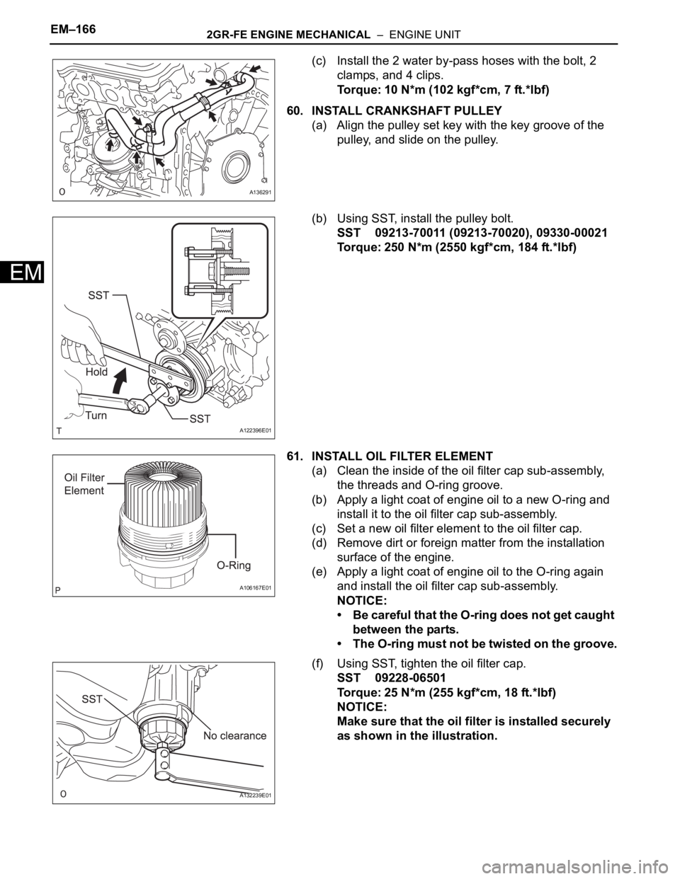
(c) Install the 2 water by-pass hoses with the bolt, 2
clamps, and 4 clips.
Torque: 10 N*m (102 kgf*cm, 7 ft.*lbf)
60. INSTALL CRANKSHAFT PULLEY
(a) Align the pulley set key with the key groove of the
pulley, and slide on the pulley.
(b) Using SST, install the pulley bolt.
SST 09213-70011 (09213-70020), 09330-00021
Torque: 250 N*m (2550 kgf*cm, 184 ft.*lbf)
61. INSTALL OIL FILTER ELEMENT
(a) Clean the inside of the oil filter cap sub-assembly,
the threads and O-ring groove.
(b) Apply a light coat of engine oil to a new O-ring and
install it to the oil filter cap sub-assembly.
(c) Set a new oil filter element to the oil filter cap.
(d) Remove dirt or foreign matter from the installation
surface of the engine.
(e) Apply a light coat of engine oil to the O-ring again
and install the oil filter cap sub-assembly.
NOTICE:
• Be careful that the O-ring does not get caught
between the parts.
• The O-ring must not be twisted on the groove.
(f) Using SST, tighten the oil filter cap.
SST 09228-06501
Torque: 25 N*m (255 kgf*cm, 18 ft.*lbf)
NOTICE:
Make sure that the oil filter is installed securely
as shown in the illustration.
A136291
A122396E01
A106167E01
A132239E01
Page 1124 of 3000
2GR-FE FUEL – FUEL SYSTEMFU–3
FU
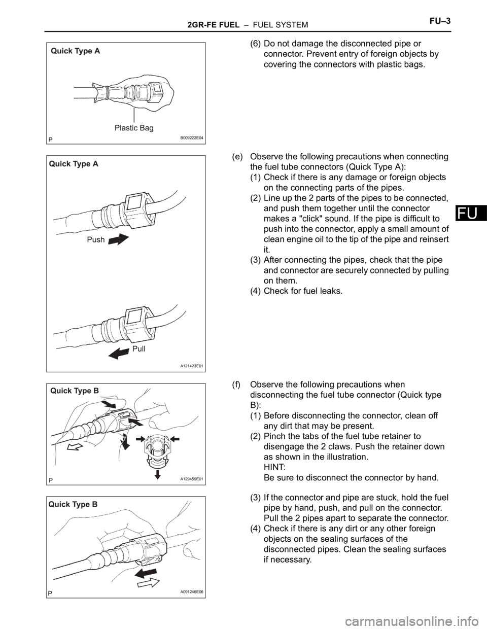
(6) Do not damage the disconnected pipe or
connector. Prevent entry of foreign objects by
covering the connectors with plastic bags.
(e) Observe the following precautions when connecting
the fuel tube connectors (Quick Type A):
(1) Check if there is any damage or foreign objects
on the connecting parts of the pipes.
(2) Line up the 2 parts of the pipes to be connected,
and push them together until the connector
makes a "click" sound. If the pipe is difficult to
push into the connector, apply a small amount of
clean engine oil to the tip of the pipe and reinsert
it.
(3) After connecting the pipes, check that the pipe
and connector are securely connected by pulling
on them.
(4) Check for fuel leaks.
(f) Observe the following precautions when
disconnecting the fuel tube connector (Quick type
B):
(1) Before disconnecting the connector, clean off
any dirt that may be present.
(2) Pinch the tabs of the fuel tube retainer to
disengage the 2 claws. Push the retainer down
as shown in the illustration.
HINT:
Be sure to disconnect the connector by hand.
(3) If the connector and pipe are stuck, hold the fuel
pipe by hand, push, and pull on the connector.
Pull the 2 pipes apart to separate the connector.
(4) Check if there is any dirt or any other foreign
objects on the sealing surfaces of the
disconnected pipes. Clean the sealing surfaces
if necessary.
B009222E04
A121423E01
A129459E01
A091246E06
Page 1125 of 3000
FU–42GR-FE FUEL – FUEL SYSTEM
FU
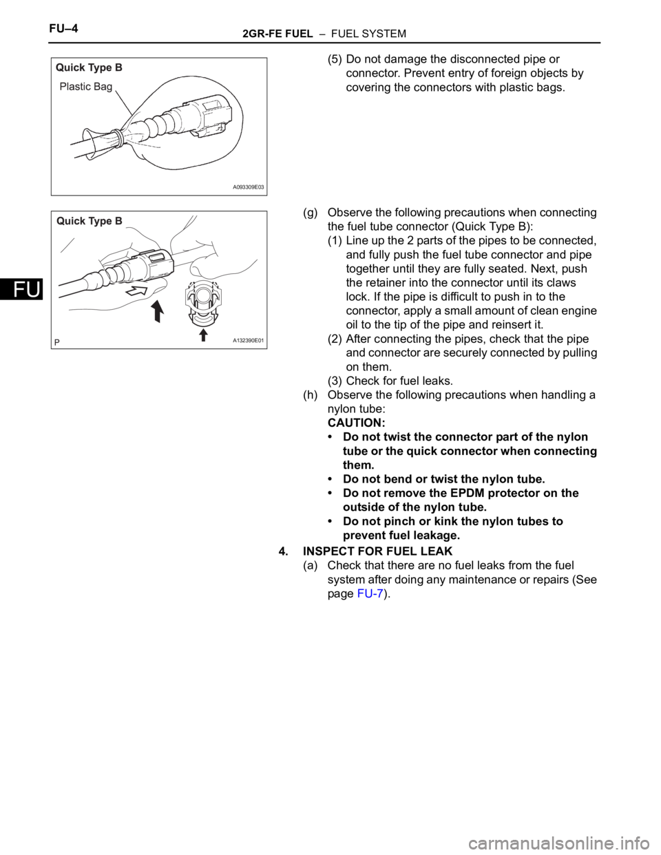
(5) Do not damage the disconnected pipe or
connector. Prevent entry of foreign objects by
covering the connectors with plastic bags.
(g) Observe the following precautions when connecting
the fuel tube connector (Quick Type B):
(1) Line up the 2 parts of the pipes to be connected,
and fully push the fuel tube connector and pipe
together until they are fully seated. Next, push
the retainer into the connector until its claws
lock. If the pipe is difficult to push in to the
connector, apply a small amount of clean engine
oil to the tip of the pipe and reinsert it.
(2) After connecting the pipes, check that the pipe
and connector are securely connected by pulling
on them.
(3) Check for fuel leaks.
(h) Observe the following precautions when handling a
nylon tube:
CAUTION:
• Do not twist the connector part of the nylon
tube or the quick connector when connecting
them.
• Do not bend or twist the nylon tube.
• Do not remove the EPDM protector on the
outside of the nylon tube.
• Do not pinch or kink the nylon tubes to
prevent fuel leakage.
4. INSPECT FOR FUEL LEAK
(a) Check that there are no fuel leaks from the fuel
system after doing any maintenance or repairs (See
page FU-7).
A093309E03
A132390E01
Page 1131 of 3000
2GR-FE FUEL – FUEL INJECTORFU–19
FU
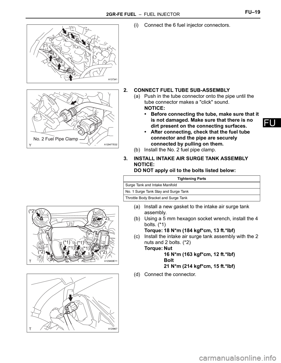
(i) Connect the 6 fuel injector connectors.
2. CONNECT FUEL TUBE SUB-ASSEMBLY
(a) Push in the tube connector onto the pipe until the
tube connector makes a "click" sound.
NOTICE:
• Before connecting the tube, make sure that it
is not damaged. Make sure that there is no
dirt present on the connecting surfaces.
• After connecting, check that the fuel tube
connector and the pipe are securely
connected by pulling on them.
(b) Install the No. 2 fuel pipe clamp.
3. INSTALL INTAKE AIR SURGE TANK ASSEMBLY
NOTICE:
DO NOT apply oil to the bolts listed below:
(a) Install a new gasket to the intake air surge tank
assembly.
(b) Using a 5 mm hexagon socket wrench, install the 4
bolts. (*1)
Torque: 18 N*m (184 kgf*cm, 13 ft.*lbf)
(c) Install the intake air surge tank assembly with the 2
nuts and 2 bolts. (*2)
Torque: Nut
16 N*m (163 kgf*cm, 12 ft.*lbf)
Bolt
21 N*m (214 kgf*cm, 15 ft.*lbf)
(d) Connect the connector.
A137341
A129477E02
Tightening Parts
Surge Tank and Intake Manifold
No. 1 Surge Tank Stay and Surge Tank
Throttle Body Bracket and Surge Tank
A129468E11
A129467
Page 1140 of 3000
2GR-FE FUEL – FUEL INJECTORFU–19
FU
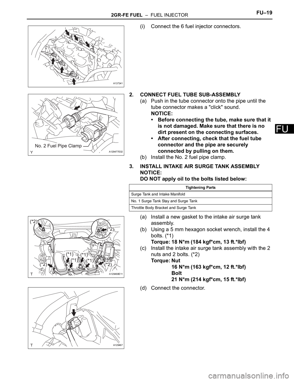
(i) Connect the 6 fuel injector connectors.
2. CONNECT FUEL TUBE SUB-ASSEMBLY
(a) Push in the tube connector onto the pipe until the
tube connector makes a "click" sound.
NOTICE:
• Before connecting the tube, make sure that it
is not damaged. Make sure that there is no
dirt present on the connecting surfaces.
• After connecting, check that the fuel tube
connector and the pipe are securely
connected by pulling on them.
(b) Install the No. 2 fuel pipe clamp.
3. INSTALL INTAKE AIR SURGE TANK ASSEMBLY
NOTICE:
DO NOT apply oil to the bolts listed below:
(a) Install a new gasket to the intake air surge tank
assembly.
(b) Using a 5 mm hexagon socket wrench, install the 4
bolts. (*1)
Torque: 18 N*m (184 kgf*cm, 13 ft.*lbf)
(c) Install the intake air surge tank assembly with the 2
nuts and 2 bolts. (*2)
Torque: Nut
16 N*m (163 kgf*cm, 12 ft.*lbf)
Bolt
21 N*m (214 kgf*cm, 15 ft.*lbf)
(d) Connect the connector.
A137341
A129477E02
Tightening Parts
Surge Tank and Intake Manifold
No. 1 Surge Tank Stay and Surge Tank
Throttle Body Bracket and Surge Tank
A129468E11
A129467