2007 TOYOTA SIENNA ECU
[x] Cancel search: ECUPage 1368 of 3000
CH–282GR-FE CHARGING – GENERATOR
CH
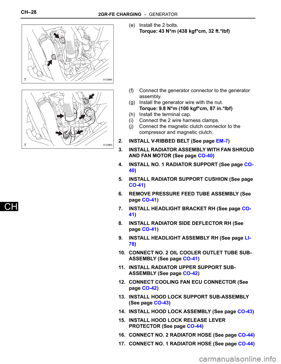
(e) Install the 2 bolts.
Torque: 43 N*m (438 kgf*cm, 32 ft.*lbf)
(f) Connect the generator connector to the generator
assembly.
(g) Install the generator wire with the nut.
Torque: 9.8 N*m (100 kgf*cm, 87 in.*lbf)
(h) Install the terminal cap.
(i) Connect the 2 wire harness clamps.
(j) Connect the magnetic clutch connector to the
compressor and magnetic clutch.
2. INSTALL V-RIBBED BELT (See page EM-7)
3. INSTALL RADIATOR ASSEMBLY WITH FAN SHROUD
AND FAN MOTOR (See page CO-40)
4. INSTALL NO. 1 RADIATOR SUPPORT (See page CO-
40)
5. INSTALL RADIATOR SUPPORT CUSHION (See page
CO-41)
6. REMOVE PRESSURE FEED TUBE ASSEMBLY (See
page CO-41)
7. INSTALL HEADLIGHT BRACKET RH (See page CO-
41)
8. INSTALL RADIATOR SIDE DEFLECTOR RH (See
page CO-41)
9. INSTALL HEADLIGHT ASSEMBLY RH (See page LI-
78)
10. CONNECT NO. 2 OIL COOLER OUTLET TUBE SUB-
ASSEMBLY (See page CO-41)
11. INSTALL RADIATOR UPPER SUPPORT SUB-
ASSEMBLY (See page CO-42)
12. CONNECT COOLING FAN ECU CONNECTOR (See
page CO-42)
13. INSTALL HOOD LOCK SUPPORT SUB-ASSEMBLY
(See page CO-43)
14. INSTALL HOOD LOCK ASSEMBLY (See page CO-43)
15. INSTALL HOOD LOCK RELEASE LEVER
PROTECTOR (See page CO-44)
16. CONNECT NO. 2 RADIATOR HOSE (See page CO-44)
17. CONNECT NO. 1 RADIATOR HOSE (See page CO-44)
A133866
A133865
Page 1377 of 3000
CH–282GR-FE CHARGING – GENERATOR
CH
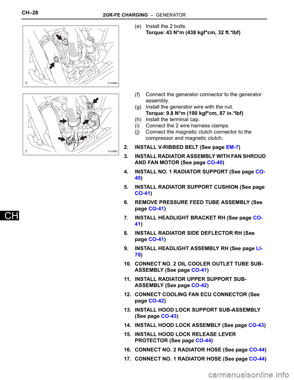
(e) Install the 2 bolts.
Torque: 43 N*m (438 kgf*cm, 32 ft.*lbf)
(f) Connect the generator connector to the generator
assembly.
(g) Install the generator wire with the nut.
Torque: 9.8 N*m (100 kgf*cm, 87 in.*lbf)
(h) Install the terminal cap.
(i) Connect the 2 wire harness clamps.
(j) Connect the magnetic clutch connector to the
compressor and magnetic clutch.
2. INSTALL V-RIBBED BELT (See page EM-7)
3. INSTALL RADIATOR ASSEMBLY WITH FAN SHROUD
AND FAN MOTOR (See page CO-40)
4. INSTALL NO. 1 RADIATOR SUPPORT (See page CO-
40)
5. INSTALL RADIATOR SUPPORT CUSHION (See page
CO-41)
6. REMOVE PRESSURE FEED TUBE ASSEMBLY (See
page CO-41)
7. INSTALL HEADLIGHT BRACKET RH (See page CO-
41)
8. INSTALL RADIATOR SIDE DEFLECTOR RH (See
page CO-41)
9. INSTALL HEADLIGHT ASSEMBLY RH (See page LI-
78)
10. CONNECT NO. 2 OIL COOLER OUTLET TUBE SUB-
ASSEMBLY (See page CO-41)
11. INSTALL RADIATOR UPPER SUPPORT SUB-
ASSEMBLY (See page CO-42)
12. CONNECT COOLING FAN ECU CONNECTOR (See
page CO-42)
13. INSTALL HOOD LOCK SUPPORT SUB-ASSEMBLY
(See page CO-43)
14. INSTALL HOOD LOCK ASSEMBLY (See page CO-43)
15. INSTALL HOOD LOCK RELEASE LEVER
PROTECTOR (See page CO-44)
16. CONNECT NO. 2 RADIATOR HOSE (See page CO-44)
17. CONNECT NO. 1 RADIATOR HOSE (See page CO-44)
A133866
A133865
Page 1411 of 3000

U151E AUTOMATIC TRANSAXLE – AUTOMATIC TRANSAXLE SYSTEMAX–45
AX
DESCRIPTION
The park/neutral position switch detects the shift lever position and sends signals to the ECM.
MONITOR DESCRIPTION
These DTCs indicate a problem with the park/neutral position switch and the wire harness in the park/
neutral position switch circuit.
The park/neutral position switch detects the shift lever position and sends a signal to the ECM.
For security, the park/neutral position switch detects the shift lever position so that engine can be started
only when the shift lever is in the P or N position
The park/neutral position switch sends a signal to the ECM according to the shift position (P, R, N or D).
The ECM determines that there is a problem with the switch or related parts if in receives more than 1
position signal simultaneously. The ECM will turn on the MIL and store the DTC.
MONITOR STRATEGY
DTC P0705Transmission Range Sensor Circuit Malfunc-
tion (PRNDL Input)
DTC No. DTC Detection Condition Trouble Area
P0705(A) Any 2 or more signals of the following are ON
simultaneously (2-trip detection logic)
• P input signal is ON.
• N input signal is ON.
• R input signal is ON.
• D input signal is ON.
• 3 input signal is ON.
• 2 input signal is ON.
(B) Any 2 or more signals of the following are ON
simultaneously (2-trip detection logic)
• NSW (STAR) input signal is ON.
• R input signal is ON.
• D input signal is ON.
• 3 input signal is ON.
• 2 input signal is ON.
(C) All switches are OFF simultaneously for NSW
(STAR), P, R, N, D, 3, 2 positions (2-trip detection
logic).
(D) Both 1 and 2 conditions are met (2-trip detection
logic)
1. One of the following conditions are met
(a) NSW (STAR) input signal is ON.
(b) P input signal is ON.
(c) N input signal is ON.
(d) R input signal is ON.
2. One of the following conditions are met
(a) 4 input signal is ON.
(b) L input signal is ON.• Short in park/neutral position switch circuit
• Park/neutral position switch
•ECM
Related DTCs P0705: Park/neutral position switch/Verify switch input
Required sensors/Components Park/neutral position switch
Frequency of operation Continuous
DurationCondition (A), (B), (D)
2 sec.
Condition (C)
60 sec.
MIL operation 2 driving cycles
Sequence of operation None
Page 1437 of 3000
U151E AUTOMATIC TRANSAXLE – AUTOMATIC TRANSAXLE SYSTEMAX–71
AX
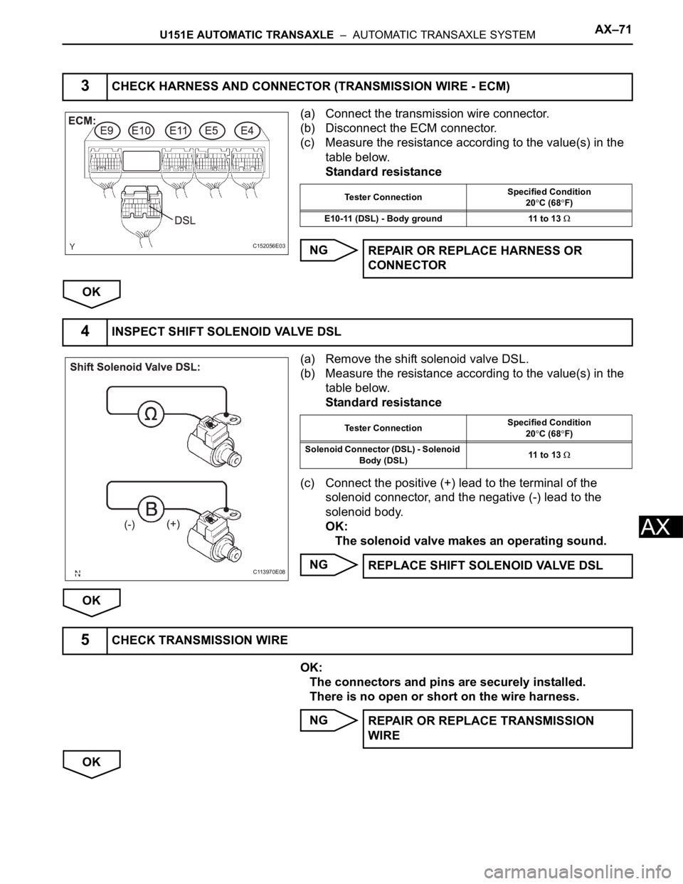
(a) Connect the transmission wire connector.
(b) Disconnect the ECM connector.
(c) Measure the resistance according to the value(s) in the
table below.
Standard resistance
NG
OK
(a) Remove the shift solenoid valve DSL.
(b) Measure the resistance according to the value(s) in the
table below.
Standard resistance
(c) Connect the positive (+) lead to the terminal of the
solenoid connector, and the negative (-) lead to the
solenoid body.
OK:
The solenoid valve makes an operating sound.
NG
OK
OK:
The connectors and pins are securely installed.
There is no open or short on the wire harness.
NG
OK
3CHECK HARNESS AND CONNECTOR (TRANSMISSION WIRE - ECM)
C152056E03
Tester ConnectionSpecified Condition
20C (68F)
E10-11 (DSL) - Body ground 11 to 13
REPAIR OR REPLACE HARNESS OR
CONNECTOR
4INSPECT SHIFT SOLENOID VALVE DSL
C113970E08
Tester ConnectionSpecified Condition
20C (68F)
Solenoid Connector (DSL) - Solenoid
Body (DSL)11 to 13
REPLACE SHIFT SOLENOID VALVE DSL
5CHECK TRANSMISSION WIRE
REPAIR OR REPLACE TRANSMISSION
WIRE
Page 1542 of 3000
U151E AUTOMATIC TRANSAXLE – AUTOMATIC TRANSAXLE SYSTEMAX–29
AX
DIAGNOSIS SYSTEM
1. DESCRIPTION
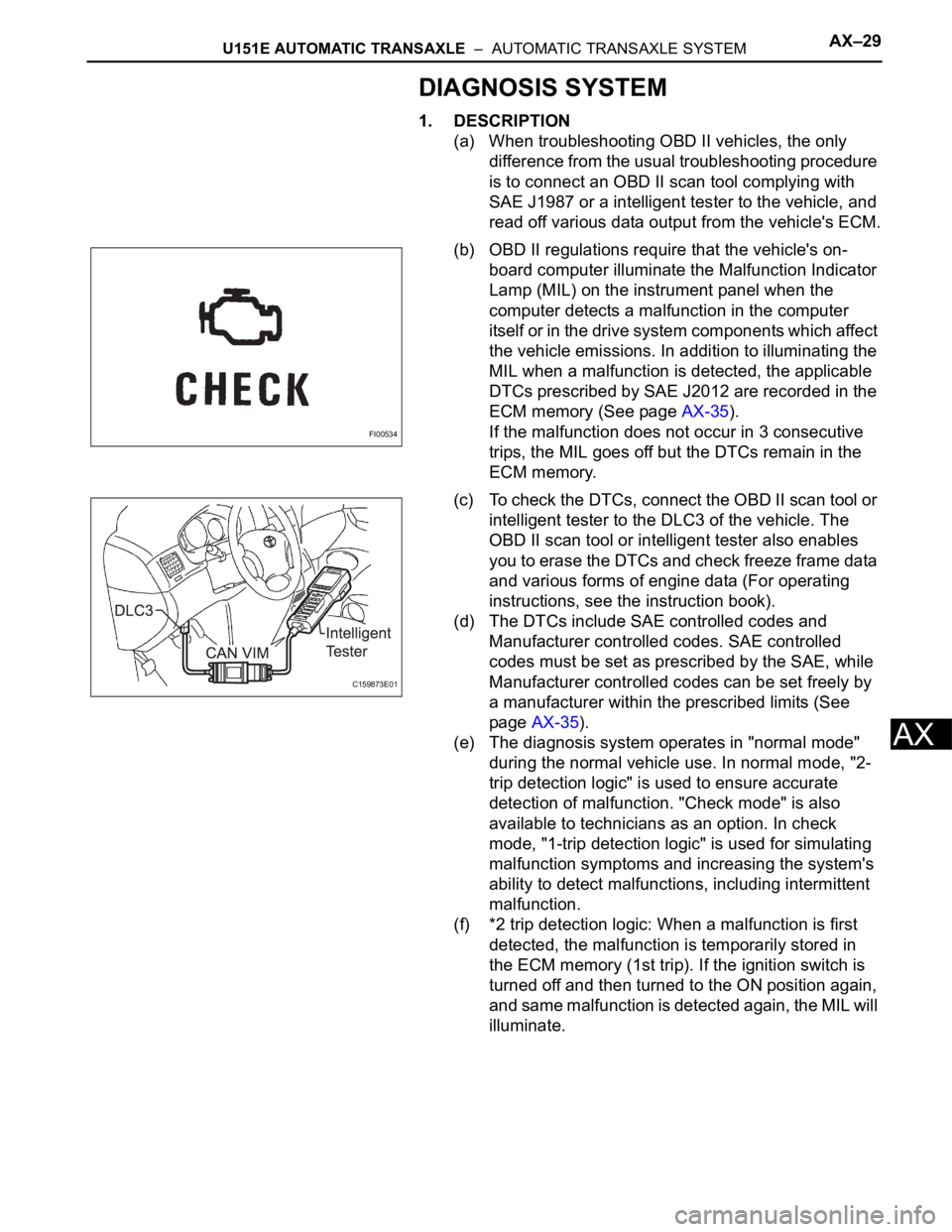
(a) When troubleshooting OBD II vehicles, the only
difference from the usual troubleshooting procedure
is to connect an OBD II scan tool complying with
SAE J1987 or a intelligent tester to the vehicle, and
read off various data output from the vehicle's ECM.
(b) OBD II regulations require that the vehicle's on-
board computer illuminate the Malfunction Indicator
Lamp (MIL) on the instrument panel when the
computer detects a malfunction in the computer
itself or in the drive system components whic h affect
the vehicle emissions. In addition to illuminating the
MIL when a malfunction is detected, the applicable
DTCs prescribed by SAE J2012 are recorded in the
ECM memory (See page AX-35).
If the malfunction does not occur in 3 consecutive
trips, the MIL goes off but the DTCs remain in the
ECM memory.
(c) To check the DTCs, connect the OBD II scan tool or
intelligent tester to the DLC3 of the vehicle. The
OBD II scan tool or intelligent tester also enables
you to erase the DTCs and check freeze frame data
and various forms of engine data (For operating
instructions, see the instruction book).
(d) The DTCs include SAE controlled codes and
Manufacturer controlled codes. SAE controlled
codes must be set as prescribed by the SAE, while
Manufacturer controlled codes can be set freely by
a manufacturer within the prescribed limits (See
page AX-35).
(e) The diagnosis system operates in "normal mode"
during the normal vehicle use. In normal mode, "2-
trip detection logic" is used to ensure accurate
detection of malfunction. "Check mode" is also
available to technicians as an option. In check
mode, "1-trip detection logic" is used for simulating
malfunction symptoms and increasing the system's
ability to detect malfunctions, including intermittent
malfunction.
(f) *2 trip detection logic: When a malfunction is first
detected, the malfunction is temporarily stored in
the ECM memory (1st trip). If the ignition switch is
turned off and then turned to the ON position again,
and same malfunction is detected again, the MIL will
illuminate.
FI00534
C159873E01
Page 1599 of 3000
U151E AUTOMATIC TRANSAXLE – AUTOMATIC TRANSAXLE UNITAX–213
AX
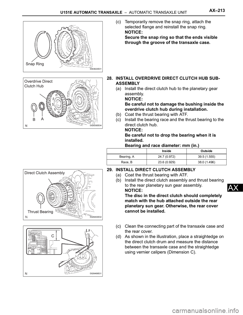
(c) Temporarily remove the snap ring, attach the
selected flange and reinstall the snap ring.
NOTICE:
Secure the snap ring so that the ends visible
through the groove of the transaxle case.
28. INSTALL OVERDRIVE DIRECT CLUTCH HUB SUB-
ASSEMBLY
(a) Install the direct clutch hub to the planetary gear
assembly.
NOTICE:
Be careful not to damage the bushing inside the
overdrive clutch hub during installation.
(b) Coat the thrust bearing with ATF.
(c) Install the bearing race and the thrust bearing to the
direct clutch hub.
NOTICE:
Be careful not to drop the bearing when it is
installed.
Bearing and race diameter: mm (in.)
29. INSTALL DIRECT CLUTCH ASSEMBLY
(a) Coat the thrust bearing with ATF.
(b) Install the direct clutch assembly and thrust bearing
to the rear planetary sun gear assembly.
NOTICE:
The disc in the direct clutch should completely
match with the hub attached outside the rear
planetary sun gear. Otherwise, the rear cover
cannot be installed.
(c) Clean the connecting part of the transaxle case and
the rear cover.
(d) As shown in the illustration, place a straightedge on
the direct clutch drum and measure the distance
between the transaxle case and the straightedge
using vernier calipers (Dimension C).
D003623E01
D026392E04
Inside Outside
Bearing, A 24.7 (0.972) 39.5 (1.555)
Race, B 23.6 (0.929) 38.0 (1.496)
D026403E02
D026469E01
Page 1600 of 3000
AX–214U151E AUTOMATIC TRANSAXLE – AUTOMATIC TRANSAXLE UNIT
AX
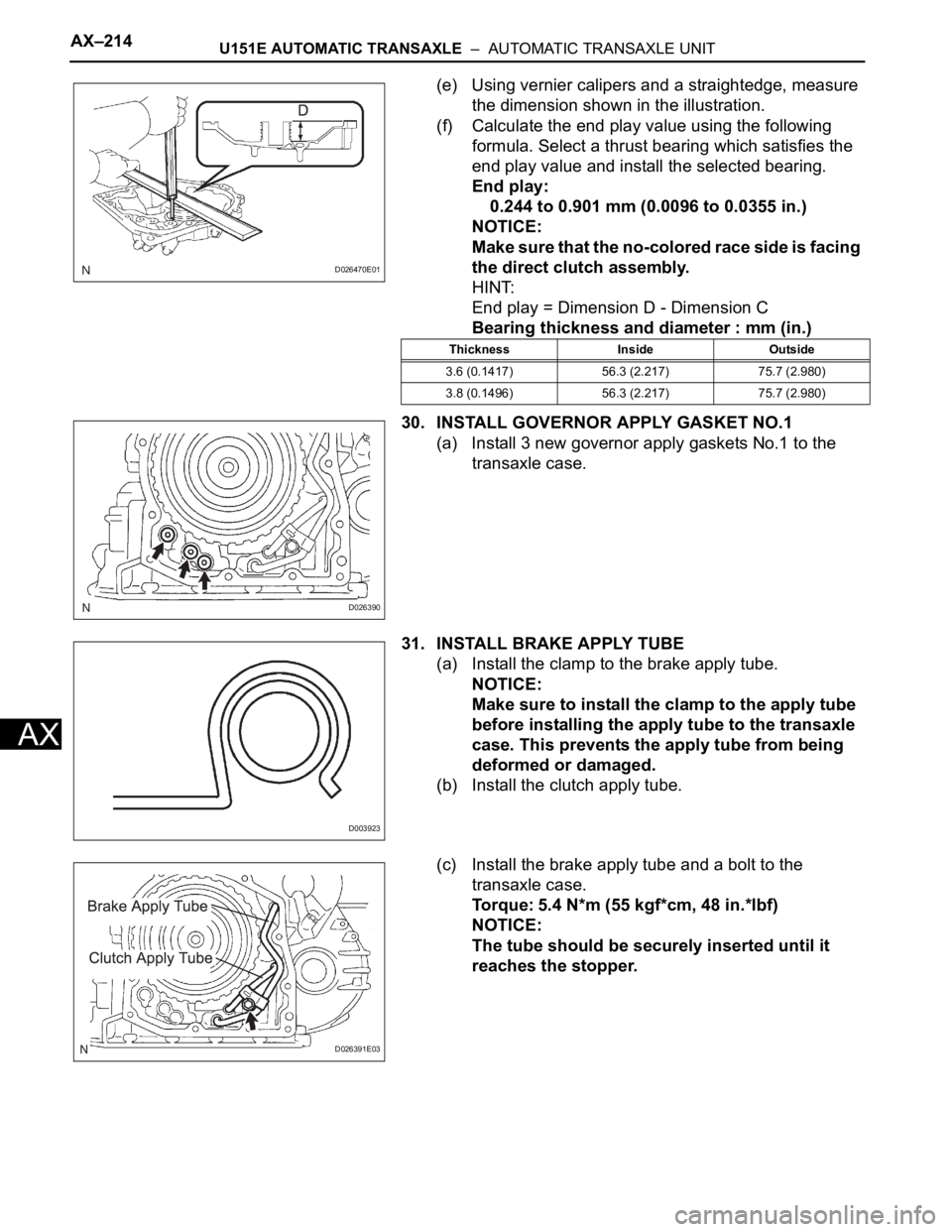
(e) Using vernier calipers and a straightedge, measure
the dimension shown in the illustration.
(f) Calculate the end play value using the following
formula. Select a thrust bearing which satisfies the
end play value and install the selected bearing.
End play:
0.244 to 0.901 mm (0.0096 to 0.0355 in.)
NOTICE:
Make sure that the no-colored race side is facing
the direct clutch assembly.
HINT:
End play = Dimension D - Dimension C
Bearing thickness and diameter : mm (in.)
30. INSTALL GOVERNOR APPLY GASKET NO.1
(a) Install 3 new governor apply gaskets No.1 to the
transaxle case.
31. INSTALL BRAKE APPLY TUBE
(a) Install the clamp to the brake apply tube.
NOTICE:
Make sure to install the clamp to the apply tube
before installing the apply tube to the transaxle
case. This prevents the apply tube from being
deformed or damaged.
(b) Install the clutch apply tube.
(c) Install the brake apply tube and a bolt to the
transaxle case.
Torque: 5.4 N*m (55 kgf*cm, 48 in.*lbf)
NOTICE:
The tube should be securely inserted until it
reaches the stopper.
D026470E01
Thickness Inside Outside
3.6 (0.1417) 56.3 (2.217) 75.7 (2.980)
3.8 (0.1496) 56.3 (2.217) 75.7 (2.980)
D026390
D003923
D026391E03
Page 1604 of 3000
AX–218U151E AUTOMATIC TRANSAXLE – AUTOMATIC TRANSAXLE UNIT
AX
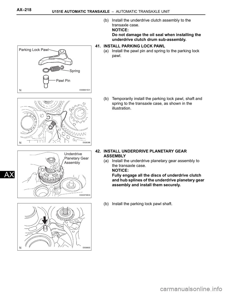
(b) Install the underdrive clutch assembly to the
transaxle case.
NOTICE:
Do not damage the oil seal when installing the
underdrive clutch drum sub-assembly.
41. INSTALL PARKING LOCK PAWL
(a) Install the pawl pin and spring to the parking lock
pawl.
(b) Temporarily install the parking lock pawl, shaft and
spring to the transaxle case, as shown in the
illustration.
42. INSTALL UNDERDRIVE PLANETARY GEAR
ASSEMBLY
(a) Install the underdrive planetary gear assembly to
the transaxle case.
NOTICE:
Fully engage all the discs of underdrive clutch
and hub splines of the underdrive planetary gear
assembly and install them securely.
(b) Install the parking lock pawl shaft.
D009691E01
D026386
D003579E03
D009693