2007 TOYOTA SIENNA ECU
[x] Cancel search: ECUPage 2075 of 3000
DS–22DRIVE SHAFT – REAR DRIVE SHAFT (for 4WD)
DS
REMOVAL
1. REMOVE REAR WHEEL
2. REMOVE TAIL EXHAUST PIPE ASSEMBLY (See page
EX-8)
3. SEPARATE REAR SPEED SENSOR
(a) Remove the bolt and the speed sensor from the
axle carrier.
NOTICE:
• Be careful not to damage the speed sensor.
• Prevent foreign matter from adhering to the
speed sensor.
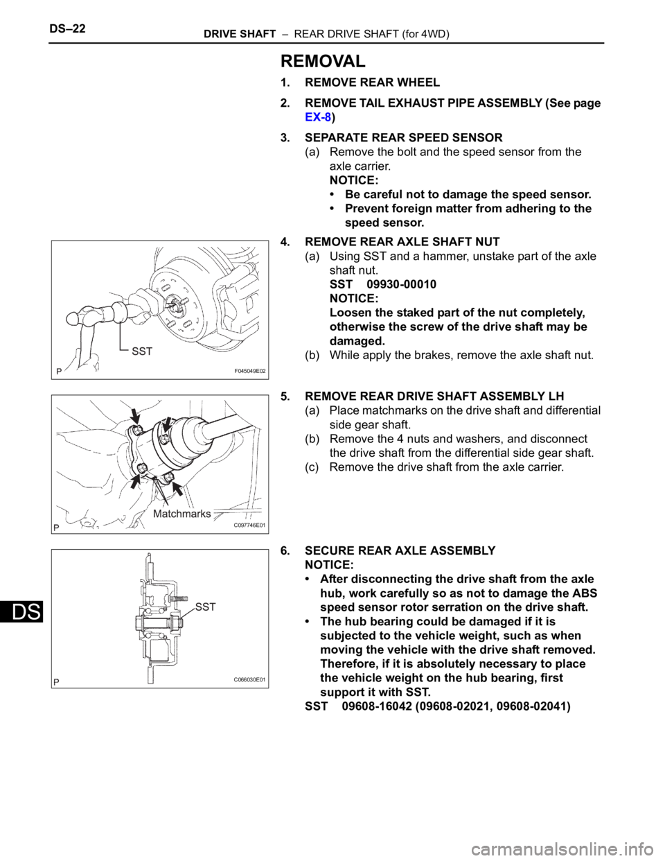
4. REMOVE REAR AXLE SHAFT NUT
(a) Using SST and a hammer, unstake part of the axle
shaft nut.
SST 09930-00010
NOTICE:
Loosen the staked part of the nut completely,
otherwise the screw of the drive shaft may be
damaged.
(b) While apply the brakes, remove the axle shaft nut.
5. REMOVE REAR DRIVE SHAFT ASSEMBLY LH
(a) Place matchmarks on the drive shaft and differential
side gear shaft.
(b) Remove the 4 nuts and washers, and disconnect
the drive shaft from the differential side gear shaft.
(c) Remove the drive shaft from the axle carrier.
6. SECURE REAR AXLE ASSEMBLY
NOTICE:
• After disconnecting the drive shaft from the axle
hub, work carefully so as not to damage the ABS
speed sensor rotor serration on the drive shaft.
• The hub bearing could be damaged if it is
subjected to the vehicle weight, such as when
moving the vehicle with the drive shaft removed.
Therefore, if it is absolutely necessary to place
the vehicle weight on the hub bearing, first
support it with SST.
SST 09608-16042 (09608-02021, 09608-02041)
F045049E02
C097746E01
C066030E01
Page 2082 of 3000
DRIVE SHAFT – FRONT DRIVE SHAFTDS–7
DS
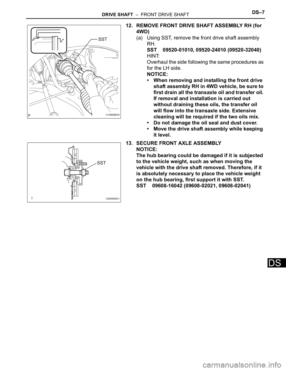
12. REMOVE FRONT DRIVE SHAFT ASSEMBLY RH (for
4WD)
(a) Using SST, remove the front drive shaft assembly
RH.
SST 09520-01010, 09520-24010 (09520-32040)
HINT:
Overhaul the side following the same procedures as
for the LH side.
NOTICE:
• When removing and installing the front drive
shaft assembly RH in 4WD vehicle, be sure to
first drain all the transaxle oil and transfer oil.
If removal and installation is carried out
without draining these oils, the transfer oil
will flow into the transaxle side. Extensive
cleaning will be required if the two oils mix.
• Do not damage the oil seal and dust cover.
• Move the drive shaft assembly while keeping
it level.
13. SECURE FRONT AXLE ASSEMBLY
NOTICE:
The hub bearing could be damaged if it is subjected
to the vehicle weight, such as when moving the
vehicle with the drive shaft removed. Therefore, if it
is absolutely necessary to place the vehicle weight
on the hub bearing, first support it with SST.
SST 09608-16042 (09608-02021, 09608-02041)
C108268E04
C054583E01
Page 2097 of 3000
DS–22DRIVE SHAFT – REAR DRIVE SHAFT (for 4WD)
DS
REMOVAL
1. REMOVE REAR WHEEL
2. REMOVE TAIL EXHAUST PIPE ASSEMBLY (See page
EX-8)
3. SEPARATE REAR SPEED SENSOR
(a) Remove the bolt and the speed sensor from the
axle carrier.
NOTICE:
• Be careful not to damage the speed sensor.
• Prevent foreign matter from adhering to the
speed sensor.
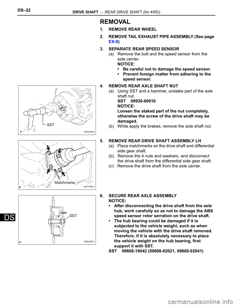
4. REMOVE REAR AXLE SHAFT NUT
(a) Using SST and a hammer, unstake part of the axle
shaft nut.
SST 09930-00010
NOTICE:
Loosen the staked part of the nut completely,
otherwise the screw of the drive shaft may be
damaged.
(b) While apply the brakes, remove the axle shaft nut.
5. REMOVE REAR DRIVE SHAFT ASSEMBLY LH
(a) Place matchmarks on the drive shaft and differential
side gear shaft.
(b) Remove the 4 nuts and washers, and disconnect
the drive shaft from the differential side gear shaft.
(c) Remove the drive shaft from the axle carrier.
6. SECURE REAR AXLE ASSEMBLY
NOTICE:
• After disconnecting the drive shaft from the axle
hub, work carefully so as not to damage the ABS
speed sensor rotor serration on the drive shaft.
• The hub bearing could be damaged if it is
subjected to the vehicle weight, such as when
moving the vehicle with the drive shaft removed.
Therefore, if it is absolutely necessary to place
the vehicle weight on the hub bearing, first
support it with SST.
SST 09608-16042 (09608-02021, 09608-02041)
F045049E02
C097746E01
C066030E01
Page 2180 of 3000
SUSPENSION – FRONT SHOCK ABSORBER WITH COIL SPRINGSP–15
SP
DISASSEMBLY
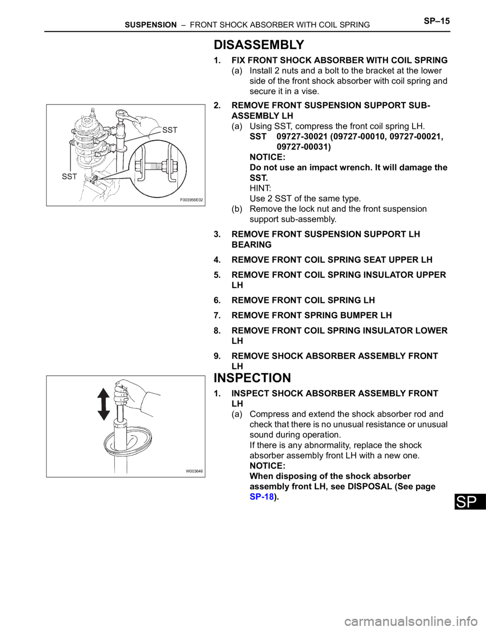
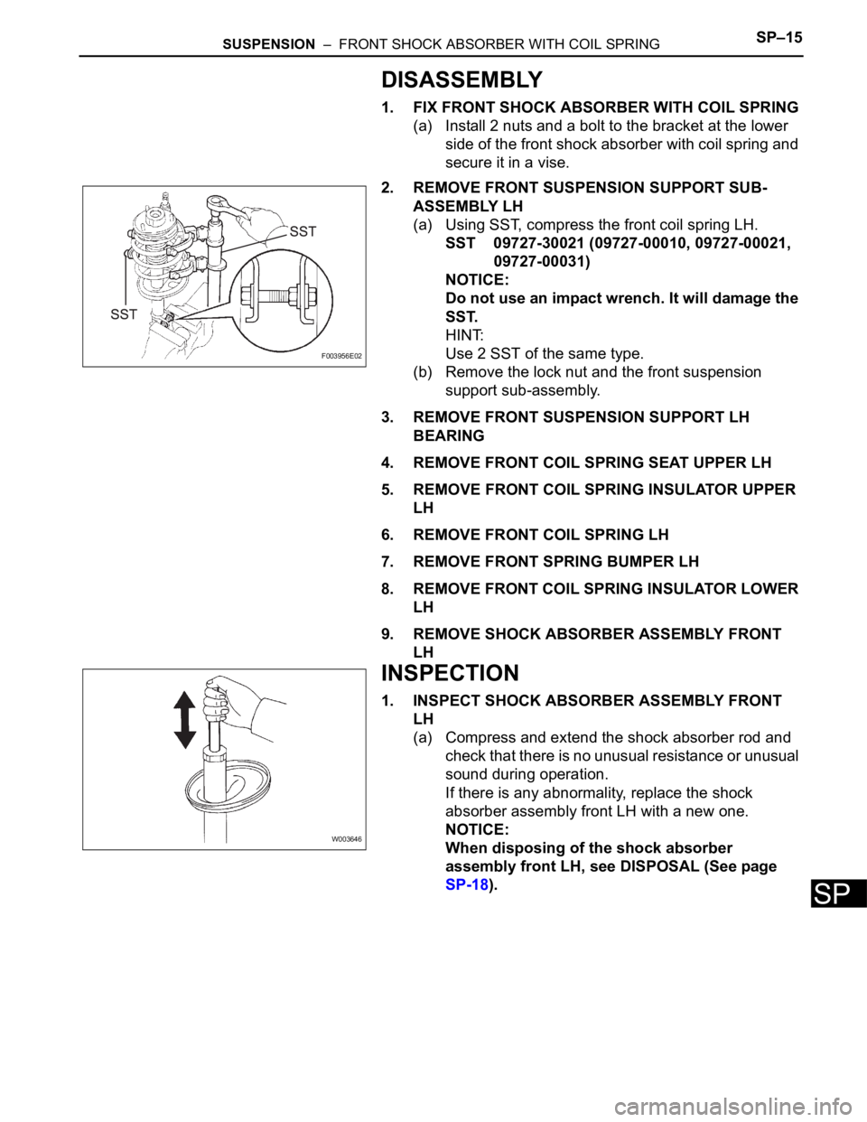
1. FIX FRONT SHOCK ABSORBER WITH COIL SPRING
(a) Install 2 nuts and a bolt to the bracket at the lower
side of the front shock absorber with coil spring and
secure it in a vise.
2. REMOVE FRONT SUSPENSION SUPPORT SUB-
ASSEMBLY LH
(a) Using SST, compress the front coil spring LH.
SST 09727-30021 (09727-00010, 09727-00021,
09727-00031)
NOTICE:
Do not use an impact wrench. It will damage the
SST.
HINT:
Use 2 SST of the same type.
(b) Remove the lock nut and the front suspension
support sub-assembly.
3. REMOVE FRONT SUSPENSION SUPPORT LH
BEARING
4. REMOVE FRONT COIL SPRING SEAT UPPER LH
5. REMOVE FRONT COIL SPRING INSULATOR UPPER
LH
6. REMOVE FRONT COIL SPRING LH
7. REMOVE FRONT SPRING BUMPER LH
8. REMOVE FRONT COIL SPRING INSULATOR LOWER
LH
9. REMOVE SHOCK ABSORBER ASSEMBLY FRONT
LH
INSPECTION
1. INSPECT SHOCK ABSORBER ASSEMBLY FRONT
LH
(a) Compress and extend the shock absorber rod and
check that there is no unusual resistance or unusual
sound during operation.
If there is any abnormality, replace the shock
absorber assembly front LH with a new one.
NOTICE:
When disposing of the shock absorber
assembly front LH, see DISPOSAL (See page
SP-18).
F003956E02
W003646
Page 2198 of 3000
SUSPENSION – FRONT SHOCK ABSORBER WITH COIL SPRINGSP–15
SP
DISASSEMBLY
1. FIX FRONT SHOCK ABSORBER WITH COIL SPRING
(a) Install 2 nuts and a bolt to the bracket at the lower
side of the front shock absorber with coil spring and
secure it in a vise.
2. REMOVE FRONT SUSPENSION SUPPORT SUB-
ASSEMBLY LH
(a) Using SST, compress the front coil spring LH.
SST 09727-30021 (09727-00010, 09727-00021,
09727-00031)
NOTICE:
Do not use an impact wrench. It will damage the
SST.
HINT:
Use 2 SST of the same type.
(b) Remove the lock nut and the front suspension
support sub-assembly.
3. REMOVE FRONT SUSPENSION SUPPORT LH
BEARING
4. REMOVE FRONT COIL SPRING SEAT UPPER LH
5. REMOVE FRONT COIL SPRING INSULATOR UPPER
LH
6. REMOVE FRONT COIL SPRING LH
7. REMOVE FRONT SPRING BUMPER LH
8. REMOVE FRONT COIL SPRING INSULATOR LOWER
LH
9. REMOVE SHOCK ABSORBER ASSEMBLY FRONT
LH
INSPECTION
1. INSPECT SHOCK ABSORBER ASSEMBLY FRONT
LH
(a) Compress and extend the shock absorber rod and
check that there is no unusual resistance or unusual
sound during operation.
If there is any abnormality, replace the shock
absorber assembly front LH with a new one.
NOTICE:
When disposing of the shock absorber
assembly front LH, see DISPOSAL (See page
SP-18).
F003956E02
W003646
Page 2243 of 3000
SUSPENSION – REAR AXLE BEAMSP–61
SP
INSTALLATION
1. INSTALL REAR AXLE BEAM DAMPER
(a) Install the rear axle beam damper to the rear axle
beam assembly.
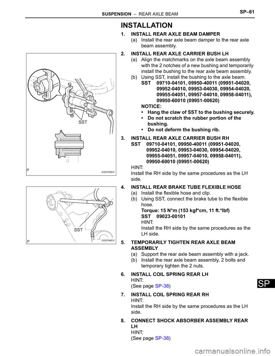
2. INSTALL REAR AXLE CARRIER BUSH LH
(a) Align the matchmarks on the axle beam assembly
with the 2 notches of a new bushing and temporarily
install the bushing to the rear axle beam assembly.
(b) Using SST, install the bushing to the axle beam.
SST 09710-04101, 09950-40011 (09951-04020,
09952-04010, 09953-04030, 09954-04020,
09955-04051, 09957-04010, 09958-04011),
09950-60010 (09951-00620)
NOTICE:
• Hang the claw of SST to the bushing securely.
• Do not scratch the rubber portion of the
bushing.
• Do not deform the bushing rib.
3. INSTALL REAR AXLE CARRIER BUSH RH
SST 09710-04101, 09950-40011 (09951-04020,
09952-04010, 09953-04030, 09954-04020,
09955-04051, 09957-04010, 09958-04011),
09950-60010 (09951-00620)
HINT:
Install the RH side by the same procedures as the LH
side.
4. INSTALL REAR BRAKE TUBE FLEXIBLE HOSE
(a) Install the flexible hose and clip.
(b) Using SST, connect the brake tube to the flexible
hose.
Torque: 15 N*m (153 kgf*cm, 11 ft.*lbf)
SST 09023-00101
HINT:
Install the RH side by the same procedures as the
LH side.
5. TEMPORARILY TIGHTEN REAR AXLE BEAM
ASSEMBLY
(a) Support the rear axle beam assembly with a jack.
(b) Install the rear axle beam assembly, 2 bolts and
temporary tighten the 2 nuts.
6. INSTALL COIL SPRING REAR LH
HINT:
(See page SP-38)
7. INSTALL COIL SPRING REAR RH
HINT:
Install the RH side by the same procedures as the LH
side.
8. CONNECT SHOCK ABSORBER ASSEMBLY REAR
LH
HINT:
(See page SP-38)
G025785E01
G025786E01
Page 2251 of 3000
TW–16TIRE AND WHEEL – TIRE PRESSURE WARNING SYSTEM
TW
SYSTEM DESCRIPTION
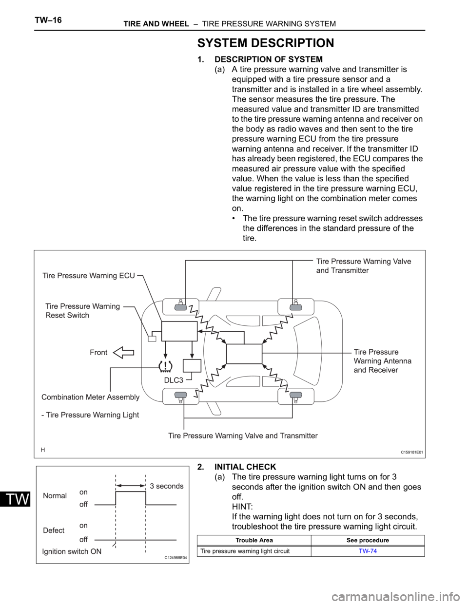
1. DESCRIPTION OF SYSTEM
(a) A tire pressure warning valve and transmitter is
equipped with a tire pressure sensor and a
transmitter and is installed in a tire wheel assembly.
The sensor measures the tire pressure. The
measured value and transmitter ID are transmitted
to the tire pressure warning antenna and receiver on
the body as radio waves and then sent to the tire
pressure warning ECU from the tire pressure
warning antenna and receiver. If the transmitter ID
has already been registered, the ECU compares the
measured air pressure value with the specified
value. When the value is less than the specified
value registered in the tire pressure warning ECU,
the warning light on the combination meter comes
on.
• The tire pressure warning reset switch addresses
the differences in the standard pressure of the
tire.
2. INITIAL CHECK
(a) The tire pressure warning light turns on for 3
seconds after the ignition switch ON and then goes
off.
HINT:
If the warning light does not turn on for 3 seconds,
troubleshoot the tire pressure warning light circuit.
C159181E01
C124985E04
Trouble Area See procedure
Tire pressure warning light circuitTW-74
Page 2252 of 3000

TIRE AND WHEEL – TIRE PRESSURE WARNING SYSTEMTW–17
TW
3. WHEN TIRE PRESSURE WARNING LIGHT IS LIT
(a) When the tire pressure warning light does not go off,
or when it comes on during driving, check tire
pressure. If the tire pressure warning light comes on
within several hours after adjusting the tire
pressure, the tire may have a slow air leak.
(b) Under the following conditions, the system may not
function properly.
• Facilities or devices that use similar radio
frequencies are located in the vicinity of the
vehicle.
• A radio device of similar frequency is used in the
vehicle.
• A large amount of snow or ice is stuck to the
vehicle, especially onto the wheels and around
the wheel houses.
• The ID of the tire pressure warning valve and
transmitter has not been registered with the
ECU.
• A film or window tint that may interfere with radio
waves is attached on the glass.
• The battery of the sensor has been depleted.
• The tires without tire pressure warning valve and
transmitter are used.
• Tire chains are used.
• The use of non-genuine wheels may result in the
system failure or air-leak.
• Depending on the tire type, the system may not
function properly even though the specified
wheels are used.
(c) After removing and installing the ECU or a sensor,
check for a diagnostic trouble code and verify that it
is a normal code.
4. FUNCTION OF COMPONENTS
5. TIRE PRESSURE WARNING RESET SWITCH
• By operating the tire pressure warning reset switch,
the tire pressure warning ECU can be set to issue a
warning at an inflation pressure that corresponds to
the standard pressure of tires.
Therefore, the dealer must set the warning threshold
to the proper value in order to comply with the local
regulations.
Components Function
Tire pressure warning valve and transmitterCombined as a single unit with a disc wheel air valve, it measures tire pressure and
temperature and transmits an ID number for measurement value and identification.
Built-in the battery.
Tire pressure warning antenna and receiverReceives and transmits a necessary signal from the transmitter to the tire pressure
warning ECU.
Tire pressure warning ECUReceives a signal from the receiver and identifies it as vehicle's own signal. If the
measured value is equal to or lower than the specified value, it transmits a signal so
that the tire pressure warning light on the combination meter comes on.
Tire pressure warning lightLocated in the combination meter, it informs the driver of lowered tire air pressure
and system failure.
Tire pressure warning reset switch Enters the initialization mode for the change of the standard pressure