Page 1261 of 3000
2GR-FE COOLING – RADIATORCO–43
CO
(b) Connect the No. 1 transmission oil cooler hoses to
the radiator.
(c) Connect the No. 1 oil cooler inlet and No. 1 oil
cooler outlet hoses to the No. 2 oil cooler outlet tube
sub-assembly.
13. INSTALL RADIATOR UPPER SUPPORT SUB-
ASSEMBLY
(a) Install the radiator upper support sub-assembly with
the 4 bolts.
Torque: 5.0 N*m (51 kgf*cm, 44 in.*lbf)
14. CONNECT COOLING FAN ECU CONNECTOR
(a) Connect the connector.
(b) Attach the clamp.
A161467E02
A161463
A161472E01
Page 1265 of 3000
2GR-FE COOLING – WATER PUMPCO–11
CO
REMOVAL
1. REMOVE ENGINE ASSEMBLY WITH TRANSAXLE
HINT:
See page EM-26
2. SECURE ENGINE (See page EM-37)
3. REMOVE GENERATOR ASSEMBLY (See page CH-17)
4. REMOVE COMPRESSOR AND MAGNETIC CLUTCH
(See page AC-227)
5. REMOVE NO. 1 ENGINE FRONT MOUNTING
BRACKET LH (See page EM-42)
6. REMOVE NO. 2 IDLER PULLEY SUB-ASSEMBLY
(a) Remove the 2 bolts, 2 idler pulley cover plates and 2
idler pulley sub-assemblies.
7. REMOVE V-RIBBED BELT TENSIONER ASSEMBLY
(a) Remove the 5 bolts and V-ribbed belt tensioner
assembly.
A129645E01
A161449
Page 1276 of 3000
2GR-FE COOLING – RADIATORCO–31
CO
(b) Detach the clamp.
(c) Disconnect the low pitched horn and high pitched
horn connectors.
(d) Remove the 2 bolts and hood lock support sub-
assembly.
15. DISCONNECT COOLING FAN ECU CONNECTOR
(a) Disconnect the cooling fan ECU connector.
(b) Detach the clamp.
16. REMOVE RADIATOR UPPER SUPPORT SUB-
ASSEMBLY
(a) Remove the 4 bolts and radiator upper support sub-
assembly.
A161458E01
A161460
A161472E01
A161463
Page 1288 of 3000
2GR-FE COOLING – RADIATORCO–43
CO
(b) Connect the No. 1 transmission oil cooler hoses to
the radiator.
(c) Connect the No. 1 oil cooler inlet and No. 1 oil
cooler outlet hoses to the No. 2 oil cooler outlet tube
sub-assembly.
13. INSTALL RADIATOR UPPER SUPPORT SUB-
ASSEMBLY
(a) Install the radiator upper support sub-assembly with
the 4 bolts.
Torque: 5.0 N*m (51 kgf*cm, 44 in.*lbf)
14. CONNECT COOLING FAN ECU CONNECTOR
(a) Connect the connector.
(b) Attach the clamp.
A161467E02
A161463
A161472E01
Page 1315 of 3000

IG–62GR-FE IGNITION – IGNITION COIL AND SPARK PLUG
IG
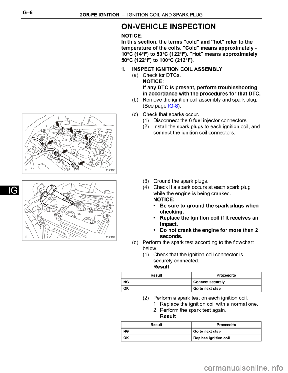
ON-VEHICLE INSPECTION
NOTICE:
In this section, the terms "cold" and "hot" refer to the
temperature of the coils. "Cold" means approximately -
10
C (14F) to 50C (122F). "Hot" means approximately
50
C (122F) to 100C (212F).
1. INSPECT IGNITION COIL ASSEMBLY
(a) Check for DTCs.
NOTICE:
If any DTC is present, perform troubleshooting
in accordance with the procedures for that DTC.
(b) Remove the ignition coil assembly and spark plug.
(See page IG-8).
(c) Check that sparks occur.
(1) Disconnect the 6 fuel injector connectors.
(2) Install the spark plugs to each ignition coil, and
connect the ignition coil connectors.
(3) Ground the spark plugs.
(4) Check if a spark occurs at each spark plug
while the engine is being cranked.
NOTICE:
• Be sure to ground the spark plugs when
checking.
• Replace the ignition coil if it receives an
impact.
• Do not crank the engine for more than 2
seconds.
(d) Perform the spark test according to the flowchart
below.
(1) Check that the ignition coil connector is
securely connected.
Result
(2) Perform a spark test on each ignition coil.
1. Replace the ignition coil with a normal one.
2. Perform the spark test again.
Result
A133895
A133897
Result Proceed to
NG Connect securely
OK Go to next step
Result Proceed to
NG Go to next step
OK Replace ignition coil
Page 1329 of 3000
ST–62GR-FE STARTING – STARTER
ST
(c) Remove the 2 bolts and the starter.
DISASSEMBLY
1. REMOVE REPAIR SERVICE STARTER KIT
(a) Remove the nut and disconnect the lead wire from
the repair service starter kit.
(b) Remove the 2 screws which are used to secure the
repair service starter kit to the repair service starter
kit.
(c) Remove the repair service starter kit.
(d) Remove the return spring and the plunger from the
repair service starter kit.
2. REMOVE STARTER YOKE ASSEMBLY
(a) Remove the 2 through bolts and pull out the starter
yoke together with the starter commutator end
frame.
(b) Remove the starter yoke from the starter
commutator end frame.
A160252
A079718
A079719
A079720
A079721
Page 1351 of 3000

CH–162GR-FE CHARGING – GENERATOR
CH
REMOVAL
1. REMOVE V-BANK COVER SUB-ASSEMBLY (See
page EM-28)
2. REMOVE FRONT WHEEL RH
3. REMOVE NO. 1 ENGINE UNDER COVER (See page
EM-26)
4. REMOVE FRONT FENDER APRON SEAL RH (See
page EM-26)
5. DRAIN ENGINE COOLANT (See page CO-6)
6. REMOVE NO. 2 AIR CLEANER INLET (See page EM-
28)
7. REMOVE BATTERY (See page EM-26)
8. REMOVE FRONT BUMPER ASSEMBLY (See page
ET-3)
9. REMOVE FRONT BUMPER ENERGY ABSORBER
10. REMOVE NO. 1 AIR CLEANER INLET (See page EM-
28)
11. DISCONNECT RADIATOR RESERVE TANK HOSE OR
PIPE (See page CO-28)
12. DISCONNECT NO. 1 RADIATOR HOSE (See page CO-
28)
13. DISCONNECT NO. 2 RADIATOR HOSE (See page CO-
29)
14. REMOVE HOOD LOCK RELEASE LEVER
PROTECTOR (See page CO-29)
15. REMOVE HOOD LOCK ASSEMBLY (See page CO-29)
16. REMOVE HOOD LOCK SUPPORT SUB-ASSEMBLY
(See page CO-29)
17. DISCONNECT COOLING FAN ECU CONNECTOR
(See page CO-30)
18. REMOVE RADIATOR UPPER SUPPORT SUB-
ASSEMBLY (See page CO-30)
19. DISCONNECT NO. 2 OIL COOLER OUTLET TUBE
SUB-ASSEMBLY (See page CO-31)
20. REMOVE HEADLIGHT ASSEMBLY RH (See page LI-
69)
21. REMOVE RADIATOR SIDE DEFLECTOR RH (See
page CO-31)
22. REMOVE HEADLIGHT BRACKET RH (See page CO-
32)
23. REMOVE PRESSURE FEED TUBE ASSEMBLY (See
page CO-32)
Page 1356 of 3000

CH–162GR-FE CHARGING – GENERATOR
CH
REMOVAL
1. REMOVE V-BANK COVER SUB-ASSEMBLY (See
page EM-28)
2. REMOVE FRONT WHEEL RH
3. REMOVE NO. 1 ENGINE UNDER COVER (See page
EM-26)
4. REMOVE FRONT FENDER APRON SEAL RH (See
page EM-26)
5. DRAIN ENGINE COOLANT (See page CO-6)
6. REMOVE NO. 2 AIR CLEANER INLET (See page EM-
28)
7. REMOVE BATTERY (See page EM-26)
8. REMOVE FRONT BUMPER ASSEMBLY (See page
ET-3)
9. REMOVE FRONT BUMPER ENERGY ABSORBER
10. REMOVE NO. 1 AIR CLEANER INLET (See page EM-
28)
11. DISCONNECT RADIATOR RESERVE TANK HOSE OR
PIPE (See page CO-28)
12. DISCONNECT NO. 1 RADIATOR HOSE (See page CO-
28)
13. DISCONNECT NO. 2 RADIATOR HOSE (See page CO-
29)
14. REMOVE HOOD LOCK RELEASE LEVER
PROTECTOR (See page CO-29)
15. REMOVE HOOD LOCK ASSEMBLY (See page CO-29)
16. REMOVE HOOD LOCK SUPPORT SUB-ASSEMBLY
(See page CO-29)
17. DISCONNECT COOLING FAN ECU CONNECTOR
(See page CO-30)
18. REMOVE RADIATOR UPPER SUPPORT SUB-
ASSEMBLY (See page CO-30)
19. DISCONNECT NO. 2 OIL COOLER OUTLET TUBE
SUB-ASSEMBLY (See page CO-31)
20. REMOVE HEADLIGHT ASSEMBLY RH (See page LI-
69)
21. REMOVE RADIATOR SIDE DEFLECTOR RH (See
page CO-31)
22. REMOVE HEADLIGHT BRACKET RH (See page CO-
32)
23. REMOVE PRESSURE FEED TUBE ASSEMBLY (See
page CO-32)