Page 1154 of 3000
FU–362GR-FE FUEL – FUEL PUMP
FU
(l) Replace the tank suction tube support.
(1) Remove the tank suction tube support from the
fuel tank.
(2) Install the tank suction tube support to the fuel
tank as shown in the illustration.
(m) Put a mark on the fuel pump gauge retainer and the
fuel tank with paint. This will be the evidence that
the fuel pump gauge retainer has been removed.
9. INSTALL FUEL TANK MAIN TUBE SUB-ASSEMBLY
(a) Install in the fuel return tube with the tube joint clip.
NOTICE:
• Check that there is no scratch or foreign
objects on the connecting part.
• Check that the fuel tube joint is inserted
securely.
• Check that the tube joint clip is on the collar
of the fuel tube joint.
• After installing the tube joint clip, check that
the fuel tube joint has not been pulled off.
10. INSTALL FUEL TANK TO FILLER PIPE HOSE (See
page FU-44)
A079527E01
A165504
A165004E01
A165008E01
Page 1159 of 3000
FU–362GR-FE FUEL – FUEL PUMP
FU
(l) Replace the tank suction tube support.
(1) Remove the tank suction tube support from the
fuel tank.
(2) Install the tank suction tube support to the fuel
tank as shown in the illustration.
(m) Put a mark on the fuel pump gauge retainer and the
fuel tank with paint. This will be the evidence that
the fuel pump gauge retainer has been removed.
9. INSTALL FUEL TANK MAIN TUBE SUB-ASSEMBLY
(a) Install in the fuel return tube with the tube joint clip.
NOTICE:
• Check that there is no scratch or foreign
objects on the connecting part.
• Check that the fuel tube joint is inserted
securely.
• Check that the tube joint clip is on the collar
of the fuel tube joint.
• After installing the tube joint clip, check that
the fuel tube joint has not been pulled off.
10. INSTALL FUEL TANK TO FILLER PIPE HOSE (See
page FU-44)
A079527E01
A165504
A165004E01
A165008E01
Page 1167 of 3000

FU–442GR-FE FUEL – FUEL TANK
FU
INSTALLATION
1. CONNECT FUEL TANK VENT HOSE
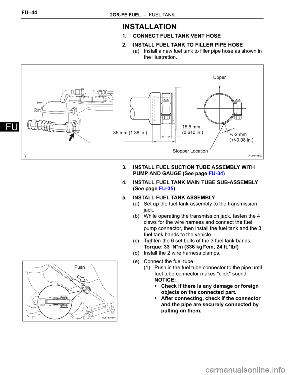
2. INSTALL FUEL TANK TO FILLER PIPE HOSE
(a) Install a new fuel tank to filler pipe hose as shown in
the illustration.
3. INSTALL FUEL SUCTION TUBE ASSEMBLY WITH
PUMP AND GAUGE (See page FU-34)
4. INSTALL FUEL TANK MAIN TUBE SUB-ASSEMBLY
(See page FU-35)
5. INSTALL FUEL TANK ASSEMBLY
(a) Set up the fuel tank assembly to the transmission
jack.
(b) While operating the transmission jack, fasten the 4
claws for the wire harness and connect the fuel
pump connector, then install the fuel tank and the 3
fuel tank bands to the vehicle.
(c) Tighten the 6 set bolts of the 3 fuel tank bands.
Torque: 33 N*m (336 kgf*cm, 24 ft.*lbf)
(d) Install the 2 wire harness clamps.
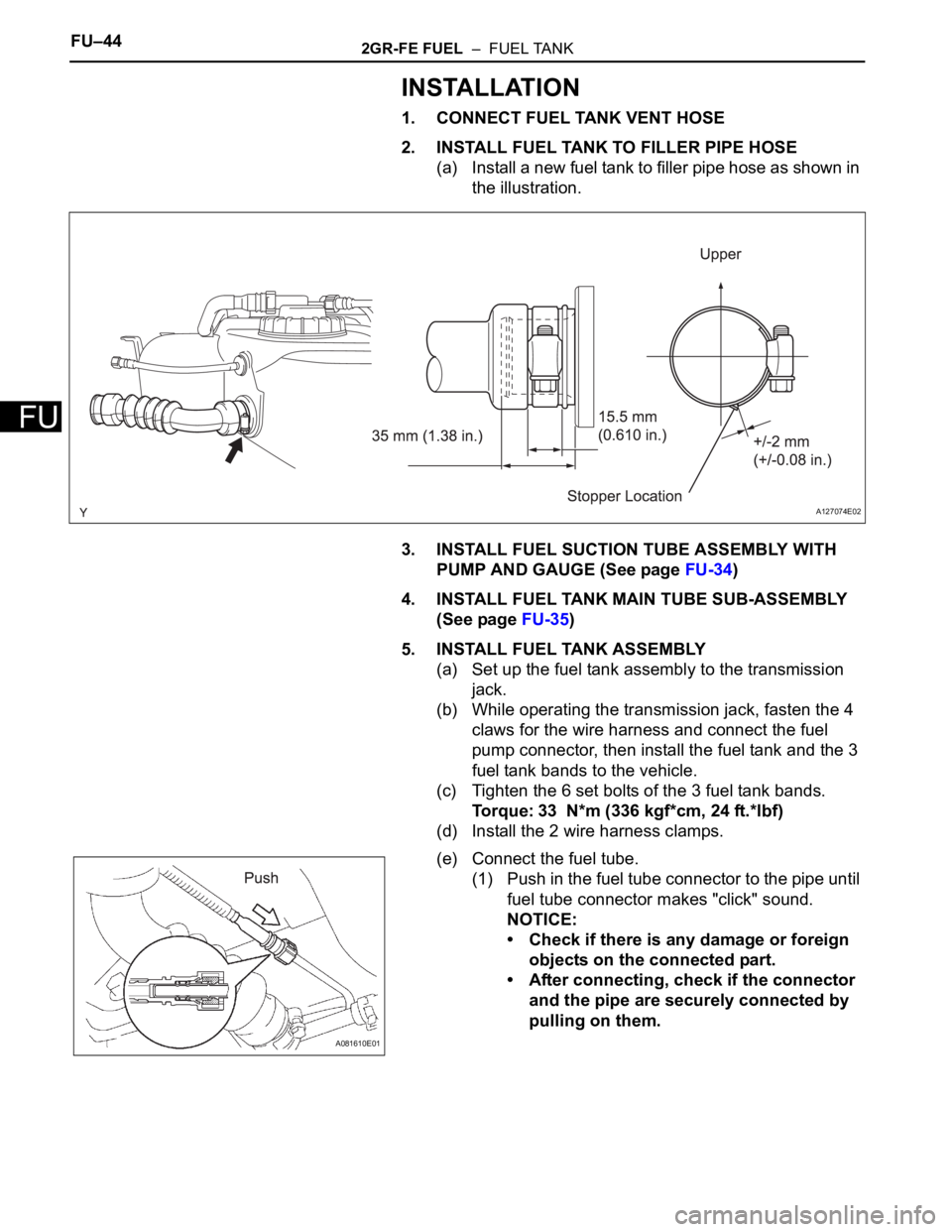
(e) Connect the fuel tube.
(1) Push in the fuel tube connector to the pipe until
fuel tube connector makes "click" sound.
NOTICE:
• Check if there is any damage or foreign
objects on the connected part.
• After connecting, check if the connector
and the pipe are securely connected by
pulling on them.
A127074E02
A081610E01
Page 1168 of 3000
2GR-FE FUEL – FUEL TANKFU–45
FU
(f) Connect the fuel tank to filler pipe hose as shown in
the illustration.
(g) Connect the fuel tank main tube.
(1) Push in the fuel tube connector to the pipe until
fuel tube connector makes "click" sound.
NOTICE:
• Check if there is any damage or foreign
objects on the connected part.
• After connecting, check if the connector
and the pipe are securely connected by
pulling on them.
(h) Connect the fuel tank vent hose.
6. ADD FUEL
7. INSPECT FOR FUEL LEAK (See page FU-7)
8. INSTALL FUEL TANK FILLER HOSE COVER
(a) Install the 3 bolts and the fuel tank filler hose cover.
Torque: 5.0 N*m (51 kgf*cm, 44 in.*lbf)
A127590E02
A081611E01
A081606E01
Page 1170 of 3000

FU–442GR-FE FUEL – FUEL TANK
FU
INSTALLATION
1. CONNECT FUEL TANK VENT HOSE
2. INSTALL FUEL TANK TO FILLER PIPE HOSE
(a) Install a new fuel tank to filler pipe hose as shown in
the illustration.
3. INSTALL FUEL SUCTION TUBE ASSEMBLY WITH
PUMP AND GAUGE (See page FU-34)
4. INSTALL FUEL TANK MAIN TUBE SUB-ASSEMBLY
(See page FU-35)
5. INSTALL FUEL TANK ASSEMBLY
(a) Set up the fuel tank assembly to the transmission
jack.
(b) While operating the transmission jack, fasten the 4
claws for the wire harness and connect the fuel
pump connector, then install the fuel tank and the 3
fuel tank bands to the vehicle.
(c) Tighten the 6 set bolts of the 3 fuel tank bands.
Torque: 33 N*m (336 kgf*cm, 24 ft.*lbf)
(d) Install the 2 wire harness clamps.
(e) Connect the fuel tube.
(1) Push in the fuel tube connector to the pipe until
fuel tube connector makes "click" sound.
NOTICE:
• Check if there is any damage or foreign
objects on the connected part.
• After connecting, check if the connector
and the pipe are securely connected by
pulling on them.
A127074E02
A081610E01
Page 1171 of 3000
2GR-FE FUEL – FUEL TANKFU–45
FU
(f) Connect the fuel tank to filler pipe hose as shown in
the illustration.
(g) Connect the fuel tank main tube.
(1) Push in the fuel tube connector to the pipe until
fuel tube connector makes "click" sound.
NOTICE:
• Check if there is any damage or foreign
objects on the connected part.
• After connecting, check if the connector
and the pipe are securely connected by
pulling on them.
(h) Connect the fuel tank vent hose.
6. ADD FUEL
7. INSPECT FOR FUEL LEAK (See page FU-7)
8. INSTALL FUEL TANK FILLER HOSE COVER
(a) Install the 3 bolts and the fuel tank filler hose cover.
Torque: 5.0 N*m (51 kgf*cm, 44 in.*lbf)
A127590E02
A081611E01
A081606E01
Page 1234 of 3000
2GR-FE COOLING – WATER PUMPCO–11
CO
REMOVAL
1. REMOVE ENGINE ASSEMBLY WITH TRANSAXLE
HINT:
See page EM-26
2. SECURE ENGINE (See page EM-37)
3. REMOVE GENERATOR ASSEMBLY (See page CH-17)
4. REMOVE COMPRESSOR AND MAGNETIC CLUTCH
(See page AC-227)
5. REMOVE NO. 1 ENGINE FRONT MOUNTING
BRACKET LH (See page EM-42)
6. REMOVE NO. 2 IDLER PULLEY SUB-ASSEMBLY
(a) Remove the 2 bolts, 2 idler pulley cover plates and 2
idler pulley sub-assemblies.
7. REMOVE V-RIBBED BELT TENSIONER ASSEMBLY
(a) Remove the 5 bolts and V-ribbed belt tensioner
assembly.
A129645E01
A161449
Page 1246 of 3000
2GR-FE COOLING – RADIATORCO–31
CO
(b) Detach the clamp.
(c) Disconnect the low pitched horn and high pitched
horn connectors.
(d) Remove the 2 bolts and hood lock support sub-
assembly.
15. DISCONNECT COOLING FAN ECU CONNECTOR
(a) Disconnect the cooling fan ECU connector.
(b) Detach the clamp.
16. REMOVE RADIATOR UPPER SUPPORT SUB-
ASSEMBLY
(a) Remove the 4 bolts and radiator upper support sub-
assembly.
A161458E01
A161460
A161472E01
A161463