Page 2768 of 3000

AC–22AIR CONDITIONING – AIR CONDITIONING SYSTEM (for Automatic Air Conditioning Sys-
tem)
AC
B1422/22 Compressor Lock Sensor
Circuit1. A/C compressor (A/C
lock sensor)
2. Compressor drive belt
3. Harness or connector
between compressor and
magnetic clutch (A/C lock
sensor)
4. A/C amplifier
5. CAN communication
system
6. Multiplex
communication system
(BEAN)-AC-47
B1423/23 Pressure Sensor Circuit 1. Pressure sensor
2. Harness or connector
between pressure sensor
and A/C amplifier
3. A/C amplifier
4. Expansion valve
(blocked, stuck)
5. Condenser (blocked,
deterioration of cooling
capacity due to dirt)
6. Cooler dryer (moisture
in the refrigerant cycle
cannot be absorbed)
7. Cooling fan system
(condenser cannot be
cooled down)
8. A/C system (leaks,
blocked)-AC-51
B1424/24
*2Solar Sensor Circuit
(Driver Side)1. Solar sensor
2. Harness or connector
between solar sensor and
A/C amplifier (A/C control
assembly)
3. Harness or connector
between solar sensor and
body ECU
4. A/C amplifier (A/C
control assembly)
5. Body ECUMemorized*3
(8.5 min. or more)
-AC-64
B1431/31 Air Mix Damper Position
Sensor Circuit (Passenger
Side)1. Air mix damper position
sensor
2. A/C amplifier (A/C
control assembly)
3. Harness or connector
between air mix damper
position sensor and A/C
amplifier (A/C control
assembly)Memorized
(1 min. or more)AC-69
B1432/32 Air Inlet Damper Position
Sensor Circuit1. Air inlet damper position
sensor (Air inlet control
servo motor)
2. A/C amplifier (A/C
control assembly)
3. Harness or connector
between air inlet damper
position sensor and A/C
amplifier (A/C control
assembly)Memorized
(1 min. or more)AC-73 DTC Code Detection Item Trouble Area Memory See page
Page 2786 of 3000
AIR CONDITIONING – AIR CONDITIONING SYSTEM (for Automatic Air Conditioning Sys-
tem)AC–43
AC
DESCRIPTION
The solar sensor, which is installed on the upper side of the instrument panel, detects sunlight and
controls the air conditioning in AUTO mode. The output voltage from the solar sensor varies according to
the amount of sunlight. When the sunlight increases, the output voltage increases. As the sunlight
decreases, the output voltage decreases. The A/C amplifier detects voltage output from the solar sensor.
DTC B1421/21 Solar Sensor Circuit (Passenger Side)
DTC No. DTC Detection Condition Trouble Area
B1421/21 Open or short in passenger side solar sensor circuit•Solar sensor
• Harness or connector between solar sensor and A/
C amplifier
• Harness or connector between solar sensor and
body ECU
• A/C amplifier
• Body ECU
E107008E01
Page 2788 of 3000
AIR CONDITIONING – AIR CONDITIONING SYSTEM (for Automatic Air Conditioning Sys-
tem)AC–45
AC
B
C
A
(a) Disconnect the solar sensor connector.
(b) Measure the voltage according to the value(s) in the
table below.
Standard voltage
OK
NG
(a) Disconnect the body ECU connector.PROCEED TO NEXT CIRCUIT INSPECTION
SHOWN IN PROBLEM SYMPTOMS TABLE
REPLACE A/C AMPLIFIER
2CHECK HARNESS AND CONNECTOR (SOLAR SENSOR)
E124476E31
Tester Connection Condition Specified Condition
A25-6 (CLTB) - A25-3
(CLTE)Ignition switch OFF Below 1 V
A25-6 (CLTB) - A25-3
(CLTE)Ignition switch ON 11 to 14 V
Go to step 4
3CHECK HARNESS AND CONNECTOR (SOLAR SENSOR - BODY ECU)
C160415E05
Page 2789 of 3000

AC–46AIR CONDITIONING – AIR CONDITIONING SYSTEM (for Automatic Air Conditioning Sys-
tem)
AC
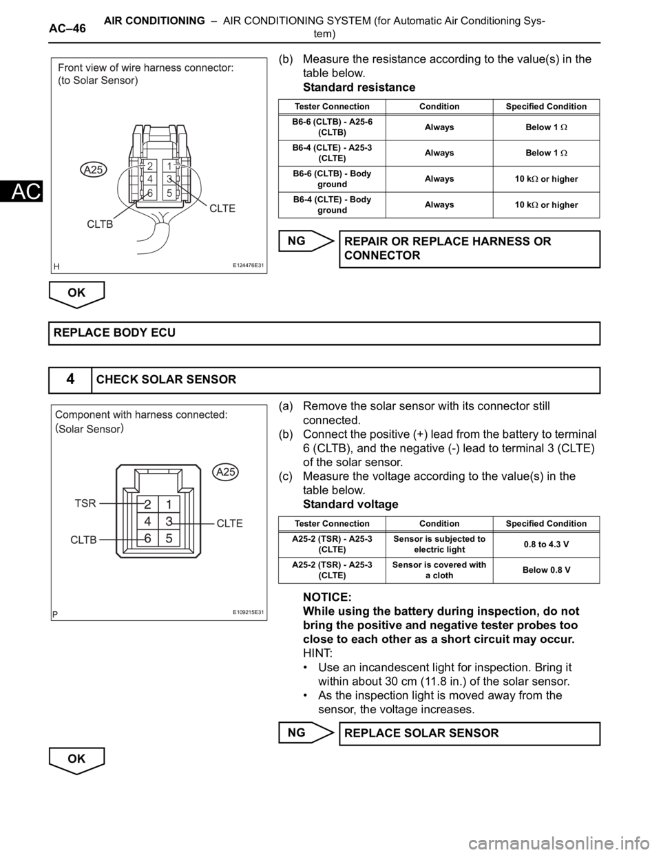
(b) Measure the resistance according to the value(s) in the
table below.
Standard resistance
NG
OK
(a) Remove the solar sensor with its connector still
connected.
(b) Connect the positive (+) lead from the battery to terminal
6 (CLTB), and the negative (-) lead to terminal 3 (CLTE)
of the solar sensor.
(c) Measure the voltage according to the value(s) in the
table below.
Standard voltage
NOTICE:
While using the battery during inspection, do not
bring the positive and negative tester probes too
close to each other as a short circuit may occur.
HINT:
• Use an incandescent light for inspection. Bring it
within about 30 cm (11.8 in.) of the solar sensor.
• As the inspection light is moved away from the
sensor, the voltage increases.
NG
OK
E124476E31
Tester Connection Condition Specified Condition
B6-6 (CLTB) - A25-6
(CLTB)Always Below 1
B6-4 (CLTE) - A25-3
(CLTE)Always Below 1
B6-6 (CLTB) - Body
groundAlways 10 k or higher
B6-4 (CLTE) - Body
groundAlways 10 k
or higher
REPAIR OR REPLACE HARNESS OR
CONNECTOR
REPLACE BODY ECU
4CHECK SOLAR SENSOR
E109215E31
Tester Connection Condition Specified Condition
A25-2 (TSR) - A25-3
(CLTE)Sensor is subjected to
electric light0.8 to 4.3 V
A25-2 (TSR) - A25-3
(CLTE)Sensor is covered with
a clothBelow 0.8 V
REPLACE SOLAR SENSOR
Page 2798 of 3000

AIR CONDITIONING – AIR CONDITIONING SYSTEM (for Automatic Air Conditioning Sys-
tem)AC–55
AC
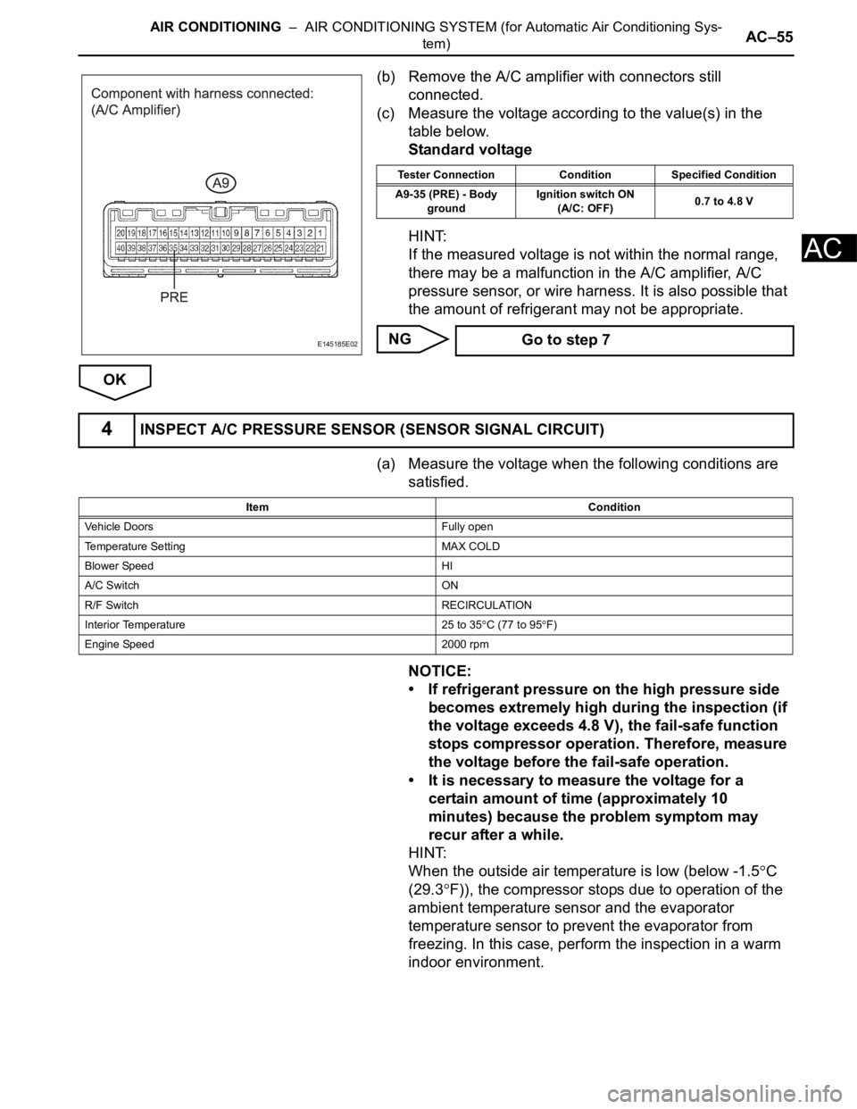
(b) Remove the A/C amplifier with connectors still
connected.
(c) Measure the voltage according to the value(s) in the
table below.
Standard voltage
HINT:
If the measured voltage is not within the normal range,
there may be a malfunction in the A/C amplifier, A/C
pressure sensor, or wire harness. It is also possible that
the amount of refrigerant may not be appropriate.
NG
OK
(a) Measure the voltage when the following conditions are
satisfied.
NOTICE:
• If refrigerant pressure on the high pressure side
becomes extremely high during the inspection (if
the voltage exceeds 4.8 V), the fail-safe function
stops compressor operation. Therefore, measure
the voltage before the fail-safe operation.
• It is necessary to measure the voltage for a
certain amount of time (approximately 10
minutes) because the problem symptom may
recur after a while.
HINT:
When the outside air temperature is low (below -1.5
C
(29.3
F)), the compressor stops due to operation of the
ambient temperature sensor and the evaporator
temperature sensor to prevent the evaporator from
freezing. In this case, perform the inspection in a warm
indoor environment.
E145185E02
Tester Connection Condition Specified Condition
A9-35 (PRE) - Body
groundIgnition switch ON
(A/C: OFF)0.7 to 4.8 V
Go to step 7
4INSPECT A/C PRESSURE SENSOR (SENSOR SIGNAL CIRCUIT)
Item Condition
Vehicle Doors Fully open
Temperature Setting MAX COLD
Blower Speed HI
A/C Switch ON
R/F Switch RECIRCULATION
Interior Temperature 25 to 35
C (77 to 95F)
Engine Speed 2000 rpm
Page 2808 of 3000
AIR CONDITIONING – AIR CONDITIONING SYSTEM (for Automatic Air Conditioning Sys-
tem)AC–65
AC
DESCRIPTION
The solar sensor, which is installed on the upper side of the instrument panel, detects sunlight and
controls the air conditioning in AUTO mode. The output voltage from the solar sensor varies according to
the amount of sunlight. When the sunlight increases, the output voltage increases. As the sunlight
decreases, the output voltage decreases. The A/C amplifier detects output voltage from the solar sensor.
DTC B1424/24 Solar Sensor Circuit (Driver Side)
DTC No. DTC Detection Condition Trouble Area
B1424/24 Open or short in driver side solar sensor circuit•Solar sensor
• Harness or connector between solar sensor and A/
C amplifier
• Harness or connector between solar sensor and
body ECU
• A/C amplifier
• Body ECU
E107008E01
Page 2810 of 3000
AIR CONDITIONING – AIR CONDITIONING SYSTEM (for Automatic Air Conditioning Sys-
tem)AC–67
AC
B
C
A
(a) Disconnect the solar sensor connector.
(b) Measure the voltage according to the value(s) in the
table below.
Standard voltage
OK
NG
(a) Disconnect the body ECU connector.PROCEED TO NEXT CIRCUIT INSPECTION
SHOWN IN PROBLEM SYMPTOMS TABLE
REPLACE A/C AMPLIFIER
2CHECK HARNESS AND CONNECTOR (SOLAR SENSOR)
E124476E31
Tester Connection Condition Specified Condition
A25-6 (CLTB) - A25-3
(CLTE)Ignition switch ON 11 to 14 V
A25-6 (CLTB) - A25-3
(CLTE)Ignition switch OFF Below 1 V
Go to step 4
3CHECK HARNESS AND CONNECTOR (SOLAR SENSOR - BODY ECU)
C160415E06
Page 2811 of 3000

AC–68AIR CONDITIONING – AIR CONDITIONING SYSTEM (for Automatic Air Conditioning Sys-
tem)
AC
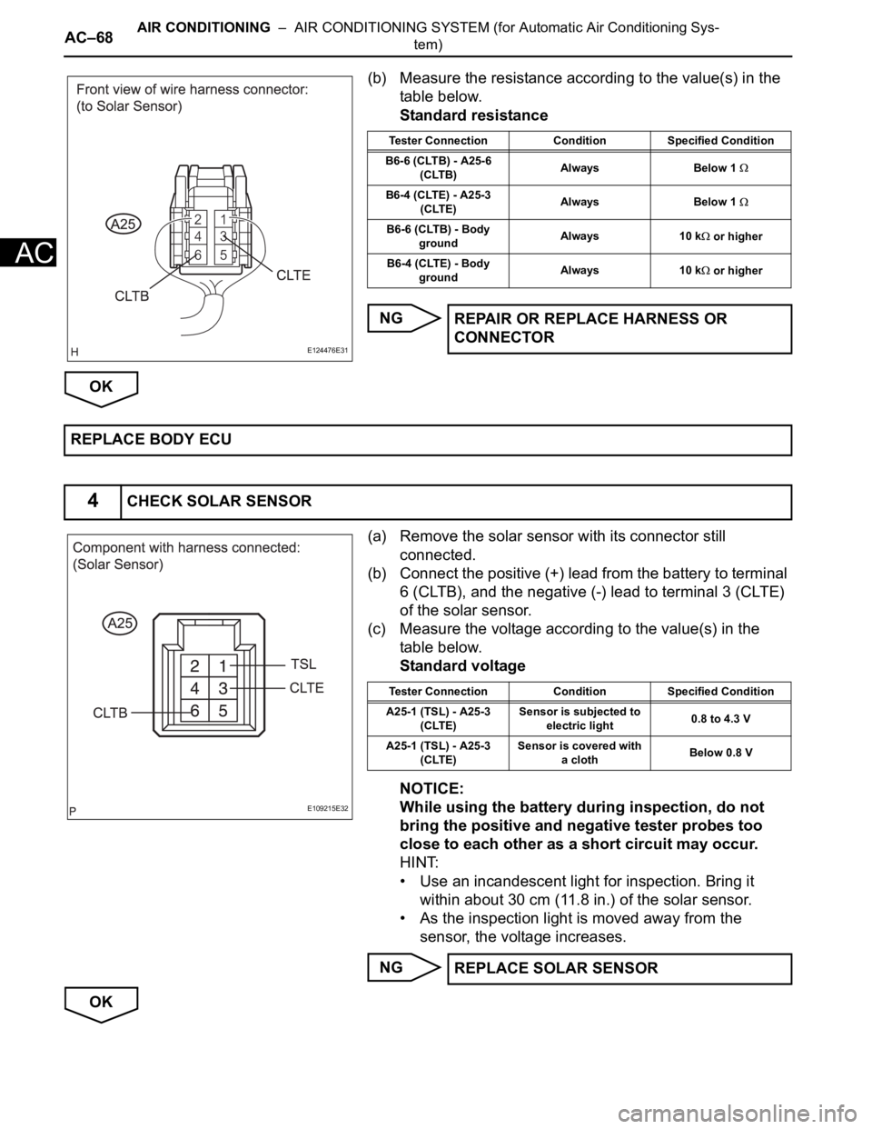
(b) Measure the resistance according to the value(s) in the
table below.
Standard resistance
NG
OK
(a) Remove the solar sensor with its connector still
connected.
(b) Connect the positive (+) lead from the battery to terminal
6 (CLTB), and the negative (-) lead to terminal 3 (CLTE)
of the solar sensor.
(c) Measure the voltage according to the value(s) in the
table below.
Standard voltage
NOTICE:
While using the battery during inspection, do not
bring the positive and negative tester probes too
close to each other as a short circuit may occur.
HINT:
• Use an incandescent light for inspection. Bring it
within about 30 cm (11.8 in.) of the solar sensor.
• As the inspection light is moved away from the
sensor, the voltage increases.
NG
OK
E124476E31
Tester Connection Condition Specified Condition
B6-6 (CLTB) - A25-6
(CLTB)Always Below 1
B6-4 (CLTE) - A25-3
(CLTE)Always Below 1
B6-6 (CLTB) - Body
groundAlways 10 k or higher
B6-4 (CLTE) - Body
groundAlways 10 k
or higher
REPAIR OR REPLACE HARNESS OR
CONNECTOR
REPLACE BODY ECU
4CHECK SOLAR SENSOR
E109215E32
Tester Connection Condition Specified Condition
A25-1 (TSL) - A25-3
(CLTE)Sensor is subjected to
electric light0.8 to 4.3 V
A25-1 (TSL) - A25-3
(CLTE)Sensor is covered with
a clothBelow 0.8 V
REPLACE SOLAR SENSOR