2007 TOYOTA SIENNA ECU
[x] Cancel search: ECUPage 2896 of 3000
AIR CONDITIONING – AIR CONDITIONING SYSTEM (for Automatic Air Conditioning Sys-
tem)AC–153
AC
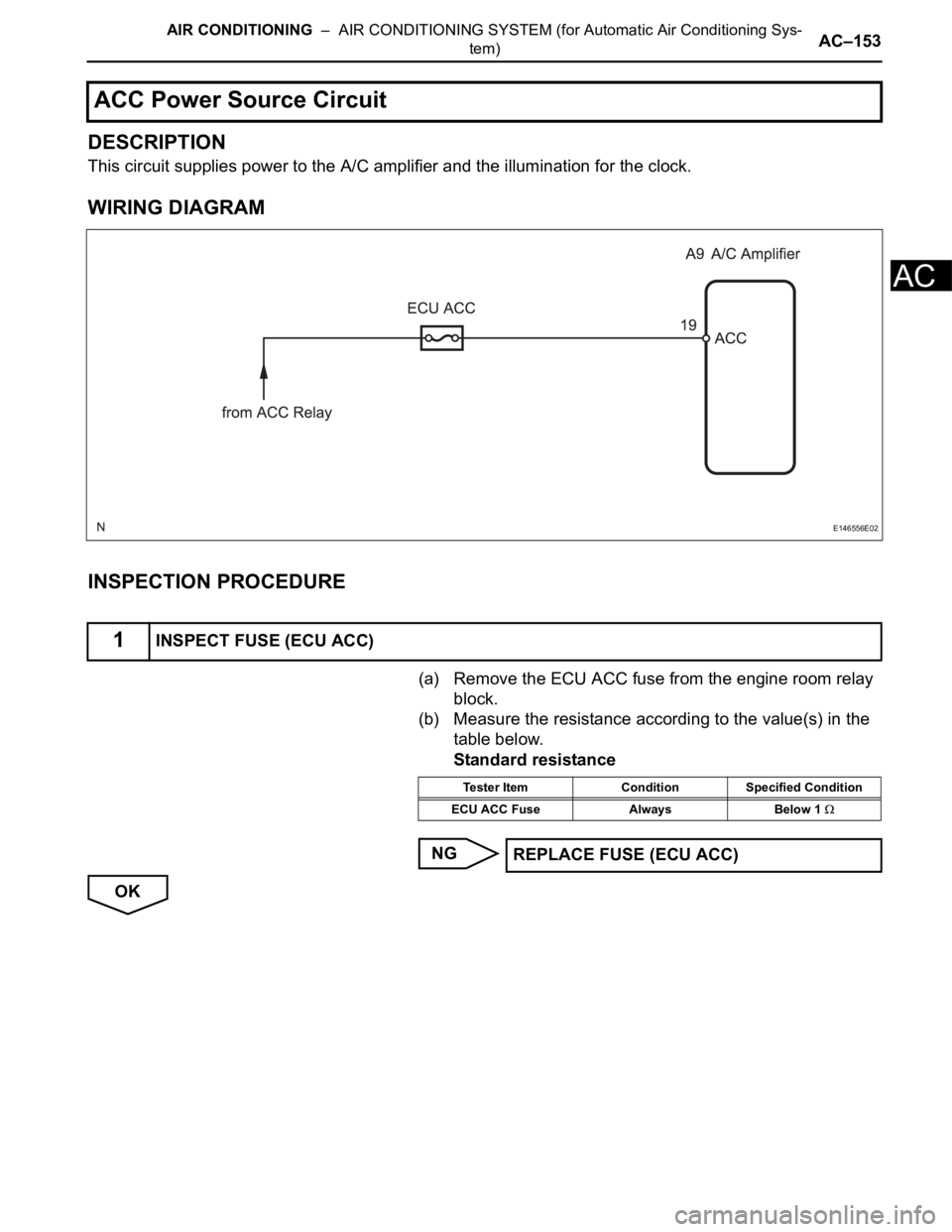
DESCRIPTION
This circuit supplies power to the A/C amplifier and the illumination for the clock.
WIRING DIAGRAM
INSPECTION PROCEDURE
(a) Remove the ECU ACC fuse from the engine room relay
block.
(b) Measure the resistance according to the value(s) in the
table below.
Standard resistance
NG
OK
ACC Power Source Circuit
1INSPECT FUSE (ECU ACC)
E146556E02
Tester Item Condition Specified Condition
ECU ACC Fuse Always Below 1
REPLACE FUSE (ECU ACC)
Page 2898 of 3000
AIR CONDITIONING – AIR CONDITIONING SYSTEM (for Automatic Air Conditioning Sys-
tem)AC–155
AC
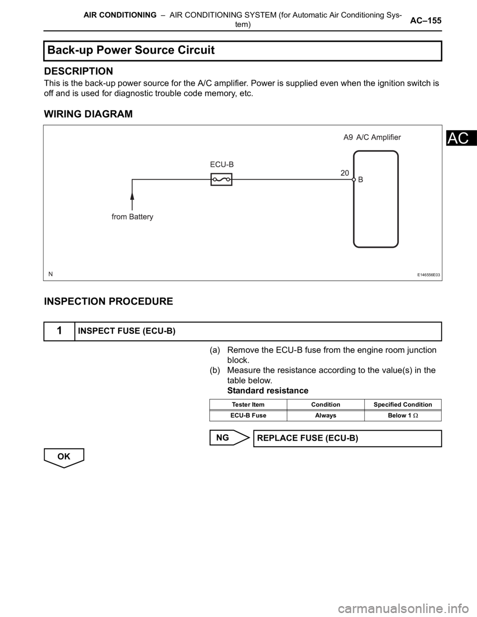
DESCRIPTION
This is the back-up power source for the A/C amplifier. Power is supplied even when the ignition switch is
off and is used for diagnostic trouble code memory, etc.
WIRING DIAGRAM
INSPECTION PROCEDURE
(a) Remove the ECU-B fuse from the engine room junction
block.
(b) Measure the resistance according to the value(s) in the
table below.
Standard resistance
NG
OK
Back-up Power Source Circuit
1INSPECT FUSE (ECU-B)
E146556E03
Tester Item Condition Specified Condition
ECU-B Fuse Always Below 1
REPLACE FUSE (ECU-B)
Page 2900 of 3000
AIR CONDITIONING – AIR CONDITIONING SYSTEM (for Automatic Air Conditioning Sys-
tem)AC–11
AC
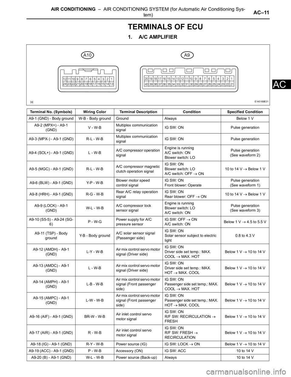
TERMINALS OF ECU
1. A/C AMPLIFIER
Terminal No. (Symbols) Wiring Color Terminal Description ConditionSpecified Condition
A9-1 (GND) - Body ground W-B - Body ground Ground Always Below 1 V
A9-2 (MPX+) - A9-1
(GND)V - W-BMultiplex communication
signalIG SW: ON Pulse generation
A9-3 (MPX-) - A9-1 (GND) R-L - W-BMultiplex communication
signalIG SW: ON Pulse generation
A9-4 (SOL+) - A9-1 (GND) L - W-BA/C compressor operation
signalEngine is running
A/C switch: ON
Blower switch: LOPulse generation
(See waveform 2)
A9-5 (MGC) - A9-1 (GND) R-L - W-BA/C compressor magnetic
clutch operation signalIG SW: ON
Blower switch: LO
A/C switch: OFF
ON10 to 14 V Below 1 V
A9-6 (BLW) - A9-1 (GND) Y-P - W-BBlower motor speed
control signalIG SW: ON
Front blower: OperatePulse generation
(See waveform 1)
A9-8 (HRH) - A9-1 (GND) R-G - W-BRear A/C relay operation
signalIG SW: ON
Rear blower: OFF
ON10 to 14 V Below 1 V
A9-9 (LOCK) - A9-1
(GND)W-L - W-BA/C compressor lock
sensor signalEngine is running
Blower switch: LO
A/C switch: ONPulse generation
(See waveform 3)
A9-10 (S5-5) - A9-24 (SG-
6)P - W-GPower supply for A/C
pressure sensorIG SW: OFF
ON
A/C switch: ONBelow 1 V 4.5 to 5.5 V
A9-11 (TSP) - Body
groundY-B - Body groundA/C solar sensor signal
(Passenger side)IG SW: ON
Solar sensor subject to electric
light0.8 to 4.3 V
A9-12 (AMDH) - A9-1
(GND)L-Y - W-BAir mix control servo motor
signal (Driver side)IG SW: ON
Driver side set temp.: MAX.
COOL
MAX. HOTBelow 1 V
10 to 14 V
A9-13 (AMDC) - A9-1
(GND)L - W-BAir mix control servo motor
signal (Driver side)IG SW: ON
Driver side set temp.: MAX.
HOT
MAX. COOLBelow 1 V 10 to 14 V
A9-14 (AMPH) - A9-1
(GND)L-B - W-BAir mix control servo motor
signal (Front passenger
side)IG SW: ON
Passenger side set temp.: MAX.
COOL
MAX. HOTBelow 1 V
10 to 14 V
A9-15 (AMPC) - A9-1
(GND)L-W - W-BAir mix control servo motor
signal (Front passenger
side)IG SW: ON
Passenger side set temp.: MAX.
HOT
MAX. COOLBelow 1 V
10 to 14 V
A9-16 (AIF) - A9-1 (GND) BR-W - W-BAir inlet control servo
motor signalIG SW: ON
R/F SW: RECIRCULATION
FRESHBelow 1 V 10 to 14 V
A9-17 (AIR) - A9-1 (GND) R - W-BAir inlet control servo
motor signalIG SW: ON
R/F SW: FRESH
RECIRCULATIONBelow 1 V 10 to 14 V
A9-18 (IG) - A9-1 (GND) R-Y - W-B Power source (IG) IG SW: LOCK
ON Below 1 V 10 to 14 V
A9-19 (ACC) - A9-1 (GND) P - W-B Accessory (ON) IG SW: ACC 10 to 14 V
A9-20 (B) - A9-1 (GND) W-L - W-B Power source (Back-up) Always 10 to 14 V
E145189E01
Page 2904 of 3000
AIR CONDITIONING – AIR CONDITIONING SYSTEM (for Automatic Air Conditioning Sys-
tem)AC–15
AC
NOTICE:
*: Before measuring the resistance, leave the
vehicle as is for at least 1 minute and do not
operate the ignition switch, any other switches
or the doors.
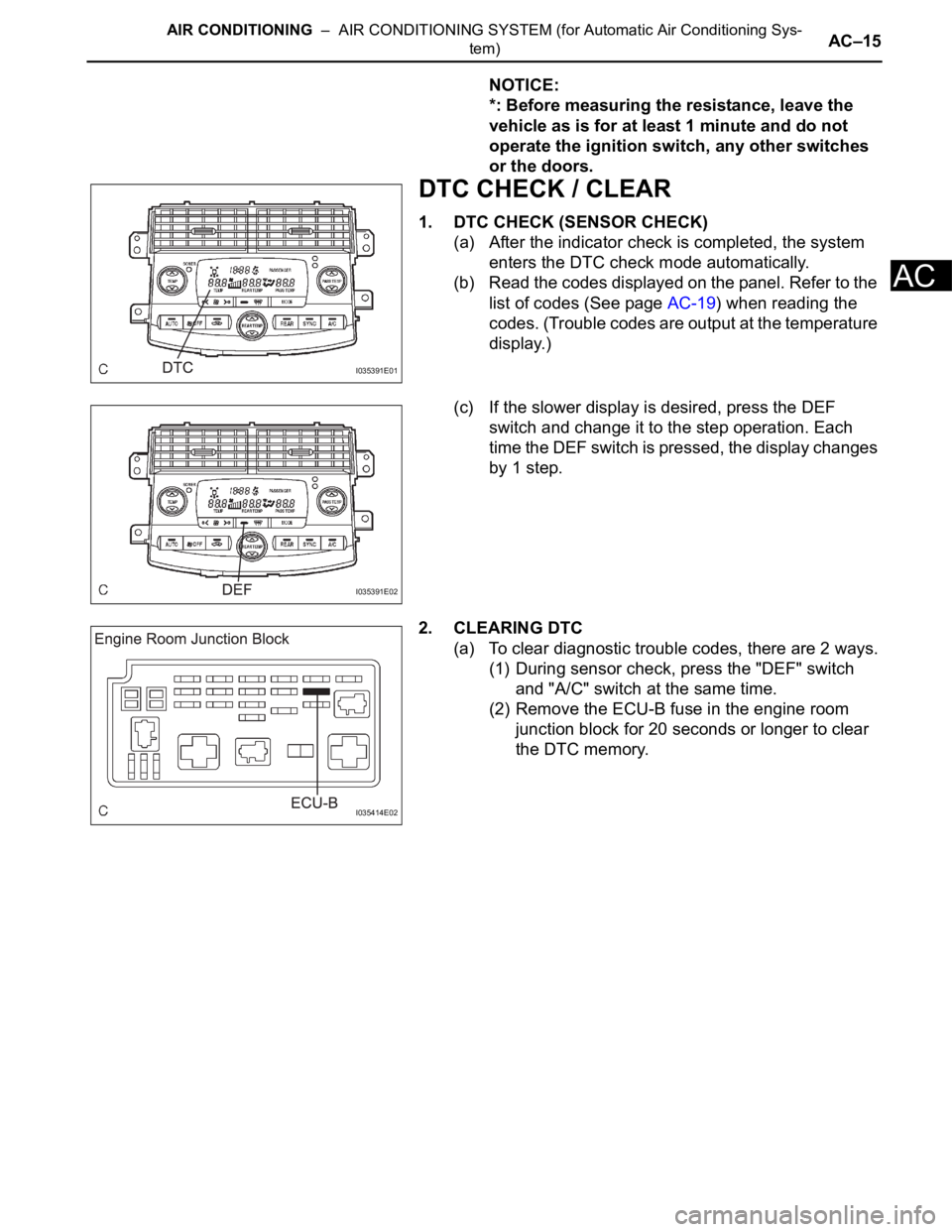
DTC CHECK / CLEAR
1. DTC CHECK (SENSOR CHECK)
(a) After the indicator check is completed, the system
enters the DTC check mode automatically.
(b) Read the codes displayed on the panel. Refer to the
list of codes (See page AC-19) when reading the
codes. (Trouble codes are output at the temperature
display.)
(c) If the slower display is desired, press the DEF
switch and change it to the step operation. Each
time the DEF switch is pressed, the display changes
by 1 step.
2. CLEARING DTC
(a) To clear diagnostic trouble codes, there are 2 ways.
(1) During sensor check, press the "DEF" switch
and "A/C" switch at the same time.
(2) Remove the ECU-B fuse in the engine room
junction block for 20 seconds or longer to clear
the DTC memory.
I035391E01
I035391E02
I035414E02
Page 2905 of 3000
AC–164AIR CONDITIONING – AIR CONDITIONING SYSTEM (for Manual Air Conditioning System)
AC
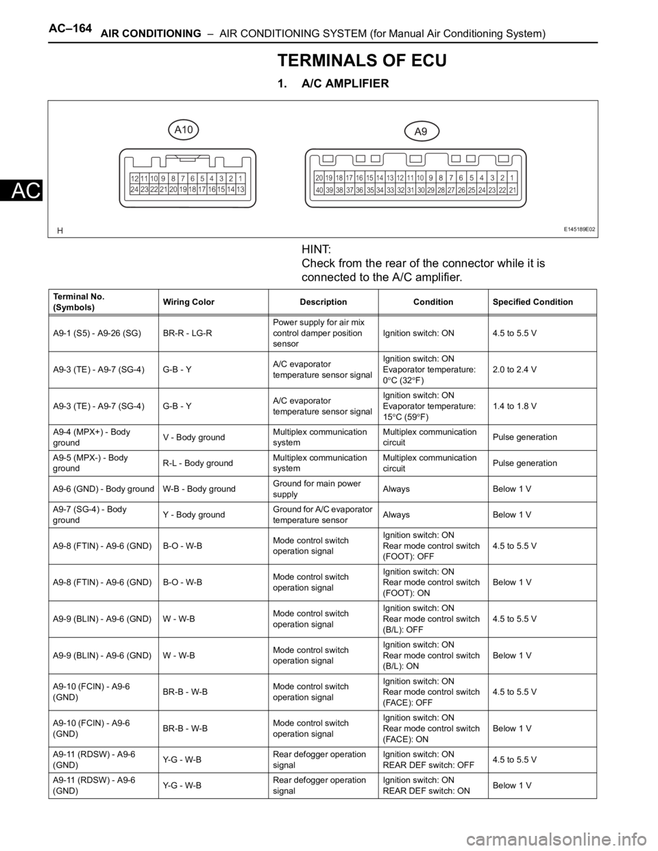
TERMINALS OF ECU
1. A/C AMPLIFIER
HINT:
Check from the rear of the connector while it is
connected to the A/C amplifier.
E145189E02
Terminal No.
(Symbols)Wiring Color Description Condition Specified Condition
A9-1 (S5) - A9-26 (SG) BR-R - LG-RPower supply for air mix
control damper position
sensorIgnition switch: ON 4.5 to 5.5 V
A9-3 (TE) - A9-7 (SG-4) G-B - YA/C evaporator
temperature sensor signalIgnition switch: ON
Evaporator temperature:
0
C (32F)2.0 to 2.4 V
A9-3 (TE) - A9-7 (SG-4) G-B - YA/C evaporator
temperature sensor signalIgnition switch: ON
Evaporator temperature:
15
C (59F)1.4 to 1.8 V
A9-4 (MPX+) - Body
groundV - Body groundMultiplex communication
systemMultiplex communication
circuitPulse generation
A9-5 (MPX-) - Body
groundR-L - Body groundMultiplex communication
systemMultiplex communication
circuitPulse generation
A9-6 (GND) - Body ground W-B - Body groundGround for main power
supplyAlways Below 1 V
A9-7 (SG-4) - Body
groundY - Body groundGround for A/C evaporator
temperature sensorAlways Below 1 V
A9-8 (FTIN) - A9-6 (GND) B-O - W-BMode control switch
operation signalIgnition switch: ON
Rear mode control switch
(FOOT): OFF4.5 to 5.5 V
A9-8 (FTIN) - A9-6 (GND) B-O - W-BMode control switch
operation signalIgnition switch: ON
Rear mode control switch
(FOOT): ONBelow 1 V
A9-9 (BLIN) - A9-6 (GND) W - W-BMode control switch
operation signalIgnition switch: ON
Rear mode control switch
(B/L): OFF4.5 to 5.5 V
A9-9 (BLIN) - A9-6 (GND) W - W-BMode control switch
operation signalIgnition switch: ON
Rear mode control switch
(B/L): ONBelow 1 V
A9-10 (FCIN) - A9-6
(GND)BR-B - W-BMode control switch
operation signalIgnition switch: ON
Rear mode control switch
(FACE): OFF4.5 to 5.5 V
A9-10 (FCIN) - A9-6
(GND)BR-B - W-BMode control switch
operation signalIgnition switch: ON
Rear mode control switch
(FACE): ONBelow 1 V
A9-11 (RDSW) - A9-6
(GND)Y- G - W - BRear defogger operation
signalIgnition switch: ON
REAR DEF switch: OFF4.5 to 5.5 V
A9-11 (RDSW) - A9-6
(GND)Y- G - W - BRear defogger operation
signalIgnition switch: ON
REAR DEF switch: ONBelow 1 V
Page 2921 of 3000
AIR CONDITIONING – AIR CONDITIONING SYSTEM (for Automatic Air Conditioning Sys-
tem)AC–21
AC
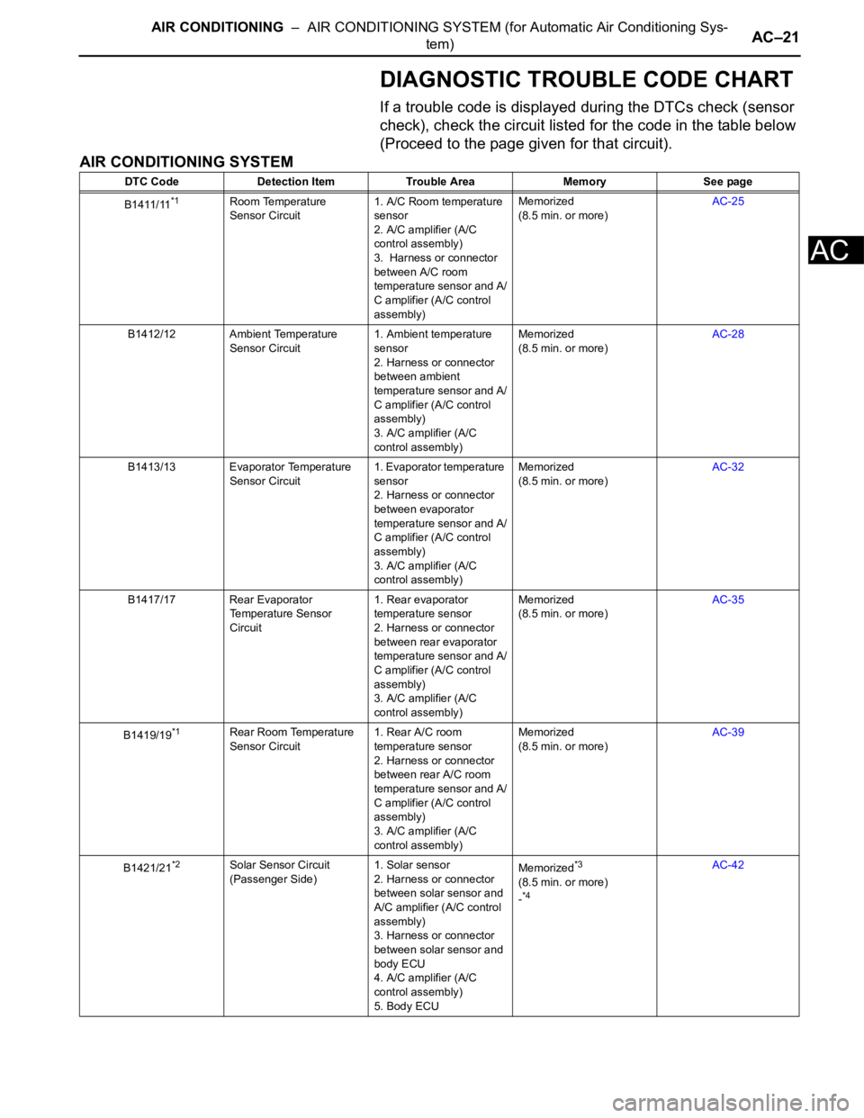
DIAGNOSTIC TROUBLE CODE CHART
If a trouble code is displayed during the DTCs check (sensor
check), check the circuit listed for the code in the table below
(Proceed to the page given for that circuit).
AIR CONDITIONING SYSTEM
DTC Code Detection Item Trouble Area Memory See page
B1411/11
*1Room Temperature
Sensor Circuit1. A/C Room temperature
sensor
2. A/C amplifier (A/C
control assembly)
3. Harness or connector
between A/C room
temperature sensor and A/
C amplifier (A/C control
assembly)Memorized
(8.5 min. or more)AC-25
B1412/12 Ambient Temperature
Sensor Circuit1. Ambient temperature
sensor
2. Harness or connector
between ambient
temperature sensor and A/
C amplifier (A/C control
assembly)
3. A/C amplifier (A/C
control assembly)Memorized
(8.5 min. or more)AC-28
B1413/13 Evaporator Temperature
Sensor Circuit1. Evaporator temperature
sensor
2. Harness or connector
between evaporator
temperature sensor and A/
C amplifier (A/C control
assembly)
3. A/C amplifier (A/C
control assembly)Memorized
(8.5 min. or more)AC-32
B1417/17 Rear Evaporator
Temperature Sensor
Circuit1. Rear evaporator
temperature sensor
2. Harness or connector
between rear evaporator
temperature sensor and A/
C amplifier (A/C control
assembly)
3. A/C amplifier (A/C
control assembly)Memorized
(8.5 min. or more)AC-35
B1419/19
*1Rear Room Temperature
Sensor Circuit1. Rear A/C room
temperature sensor
2. Harness or connector
between rear A/C room
temperature sensor and A/
C amplifier (A/C control
assembly)
3. A/C amplifier (A/C
control assembly)Memorized
(8.5 min. or more)AC-39
B1421/21
*2Solar Sensor Circuit
(Passenger Side)1. Solar sensor
2. Harness or connector
between solar sensor and
A/C amplifier (A/C control
assembly)
3. Harness or connector
between solar sensor and
body ECU
4. A/C amplifier (A/C
control assembly)
5. Body ECUMemorized*3
(8.5 min. or more)
-*4
AC-42
Page 2922 of 3000
AC–22AIR CONDITIONING – AIR CONDITIONING SYSTEM (for Automatic Air Conditioning Sys-
tem)
AC
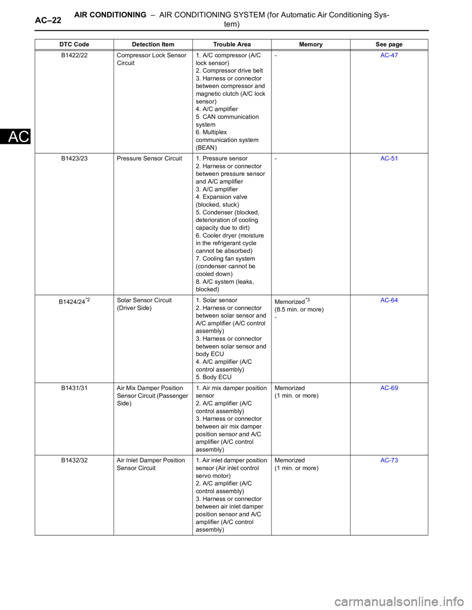
B1422/22 Compressor Lock Sensor
Circuit1. A/C compressor (A/C
lock sensor)
2. Compressor drive belt
3. Harness or connector
between compressor and
magnetic clutch (A/C lock
sensor)
4. A/C amplifier
5. CAN communication
system
6. Multiplex
communication system
(BEAN)-AC-47
B1423/23 Pressure Sensor Circuit 1. Pressure sensor
2. Harness or connector
between pressure sensor
and A/C amplifier
3. A/C amplifier
4. Expansion valve
(blocked, stuck)
5. Condenser (blocked,
deterioration of cooling
capacity due to dirt)
6. Cooler dryer (moisture
in the refrigerant cycle
cannot be absorbed)
7. Cooling fan system
(condenser cannot be
cooled down)
8. A/C system (leaks,
blocked)-AC-51
B1424/24
*2Solar Sensor Circuit
(Driver Side)1. Solar sensor
2. Harness or connector
between solar sensor and
A/C amplifier (A/C control
assembly)
3. Harness or connector
between solar sensor and
body ECU
4. A/C amplifier (A/C
control assembly)
5. Body ECUMemorized*3
(8.5 min. or more)
-AC-64
B1431/31 Air Mix Damper Position
Sensor Circuit (Passenger
Side)1. Air mix damper position
sensor
2. A/C amplifier (A/C
control assembly)
3. Harness or connector
between air mix damper
position sensor and A/C
amplifier (A/C control
assembly)Memorized
(1 min. or more)AC-69
B1432/32 Air Inlet Damper Position
Sensor Circuit1. Air inlet damper position
sensor (Air inlet control
servo motor)
2. A/C amplifier (A/C
control assembly)
3. Harness or connector
between air inlet damper
position sensor and A/C
amplifier (A/C control
assembly)Memorized
(1 min. or more)AC-73 DTC Code Detection Item Trouble Area Memory See page
Page 2992 of 3000

SUPPLEMENTAL RESTRAINT SYSTEM – AIRBAG SYSTEMRS–15
RS
SYSTEM DESCRIPTION
1. GENERAL
(a) In conjunction with impact absorbing structure for a
frontal collision, the SRS (Supplemental Restraint
System) driver airbag and front passenger airbag
were designed to supplement seat belts in the event
of a frontal collision in order to help reduce shock to
the head and chest. This system is a 3-sensor type
airbag system to detect the impact during a frontal
collision using the center airbag sensor assembly
and front airbag sensors. It also operates the airbag
system and seat belt pretensioner.
(b) In order to detect the extent of the collision during
the initial stages of the collision in further detail, the
front airbag sensors have been changed from
mechanical type to electrical type deceleration
sensors. Accordingly, the deployment of the driver
airbag and front passenger airbag is controlled in
two stages according to the severity of the impact.
(c) In conjunction with impact absorbing structure for a
side collision, the front seat side airbag and curtain
shield airbag were designed to help reduce shock to
the driver, front passenger, and rear outer
passengers in the event of a side collision or
rollover.
(d) RSCA (Roll Sensing of Curtain Shield Airbags) is
used in order to deploy the curtain shield airbags
and the seat belt pretensioner for the driver and
front passenger, in the event that the vehicle rolls
over.
(e) The curtain shield airbag that helps reduce shock to
the front and rear seat occupants with a single
curtain shield airbag has been adopted. In
conjunction with this system, the side airbag
sensors have been installed at the bottom of the
center pillars and the rear airbag sensors have been
installed at the bottom of the rear pillars
respectively.
(f) In this system, a front side collision is detected by
the side airbag sensors in order to deploy the front
seat side airbag and curtain shield airbag. A rear
side collision is detected by the rear airbag sensors
and the center airbag sensor assembly in order to
deploy the curtain shield airbag.
(g) The center airbag sensor assembly sends the
airbag deployment signal to the ECM through BEAN
(Body Electronics Area Network) and CAN
(Controller Area Network) to operate the fuel pump
control.
(h) The center airbag sensor assembly sends the
airbag deployment signal to the body ECU via a
discrete line to operate collision door lock release
control.