Page 2582 of 3000
BRAKE CONTROL – ANTI-LOCK BRAKE SYSTEMBC–39
BC
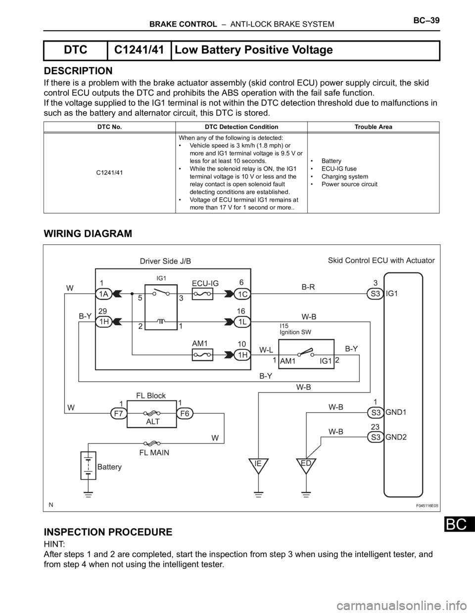
DESCRIPTION
If there is a problem with the brake actuator assembly (skid control ECU) power supply circuit, the skid
control ECU outputs the DTC and prohibits the ABS operation with the fail safe function.
If the voltage supplied to the IG1 terminal is not within the DTC detection threshold due to malfunctions in
such as the battery and alternator circuit, this DTC is stored.
WIRING DIAGRAM
INSPECTION PROCEDURE
HINT:
After steps 1 and 2 are completed, start the inspection from step 3 when using the intelligent tester, and
from step 4 when not using the intelligent tester.
DTC C1241/41 Low Battery Positive Voltage
DTC No. DTC Detection Condition Trouble Area
C1241/41When any of the following is detected:
• Vehicle speed is 3 km/h (1.8 mph) or
more and IG1 terminal voltage is 9.5 V or
less for at least 10 seconds.
• While the solenoid relay is ON, the IG1
terminal voltage is 10 V or less and the
relay contact is open solenoid fault
detecting conditions are established.
• Voltage of ECU terminal IG1 remains at
more than 17 V for 1 second or more..• Battery
•ECU-IG fuse
• Charging system
• Power source circuit
F045116E05
Page 2583 of 3000
BC–40BRAKE CONTROL – ANTI-LOCK BRAKE SYSTEM
BC
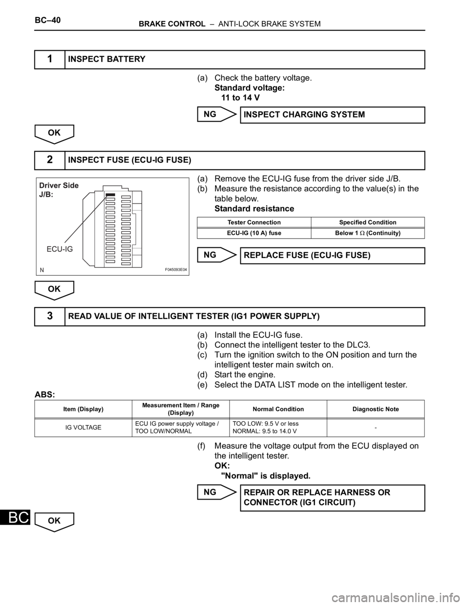
(a) Check the battery voltage.
Standard voltage:
11 to 14 V
NG
OK
(a) Remove the ECU-IG fuse from the driver side J/B.
(b) Measure the resistance according to the value(s) in the
table below.
Standard resistance
NG
OK
(a) Install the ECU-IG fuse.
(b) Connect the intelligent tester to the DLC3.
(c) Turn the ignition switch to the ON position and turn the
intelligent tester main switch on.
(d) Start the engine.
(e) Select the DATA LIST mode on the intelligent tester.
ABS:
(f) Measure the voltage output from the ECU displayed on
the intelligent tester.
OK:
"Normal" is displayed.
NG
OK
1INSPECT BATTERY
INSPECT CHARGING SYSTEM
2INSPECT FUSE (ECU-IG FUSE)
F045093E04
Tester Connection Specified Condition
ECU-IG (10 A) fuse Below 1
(Continuity)
REPLACE FUSE (ECU-IG FUSE)
3READ VALUE OF INTELLIGENT TESTER (IG1 POWER SUPPLY)
Item (Display)Measurement Item / Range
(Display)Normal Condition Diagnostic Note
IG VOLTAGEECU IG power supply voltage /
TOO LOW/NORMALTOO LOW: 9.5 V or less
NORMAL: 9.5 to 14.0 V-
REPAIR OR REPLACE HARNESS OR
CONNECTOR (IG1 CIRCUIT)
Page 2584 of 3000
BRAKE CONTROL – ANTI-LOCK BRAKE SYSTEMBC–41
BC
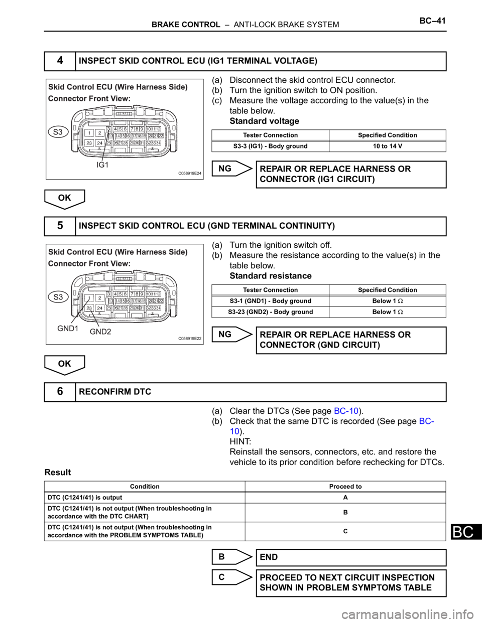
(a) Disconnect the skid control ECU connector.
(b) Turn the ignition switch to ON position.
(c) Measure the voltage according to the value(s) in the
table below.
Standard voltage
NG
OK
(a) Turn the ignition switch off.
(b) Measure the resistance according to the value(s) in the
table below.
Standard resistance
NG
OK
(a) Clear the DTCs (See page BC-10).
(b) Check that the same DTC is recorded (See page BC-
10).
HINT:
Reinstall the sensors, connectors, etc. and restore the
vehicle to its prior condition before rechecking for DTCs.
Result
B
C
4INSPECT SKID CONTROL ECU (IG1 TERMINAL VOLTAGE)
C058919E24
Tester Connection Specified Condition
S3-3 (IG1) - Body ground 10 to 14 V
REPAIR OR REPLACE HARNESS OR
CONNECTOR (IG1 CIRCUIT)
5INSPECT SKID CONTROL ECU (GND TERMINAL CONTINUITY)
C058919E22
Tester Connection Specified Condition
S3-1 (GND1) - Body ground Below 1
S3-23 (GND2) - Body ground Below 1
REPAIR OR REPLACE HARNESS OR
CONNECTOR (GND CIRCUIT)
6RECONFIRM DTC
Condition Proceed to
DTC (C1241/41) is outputA
DTC (C1241/41) is not output (When troubleshooting in
accordance with the DTC CHART)B
DTC (C1241/41) is not output (When troubleshooting in
accordance with the PROBLEM SYMPTOMS TABLE)C
END
PROCEED TO NEXT CIRCUIT INSPECTION
SHOWN IN PROBLEM SYMPTOMS TABLE
Page 2588 of 3000

BRAKE – BRAKE PEDALBR–13
BR
REASSEMBLY
1. INSTALL BRAKE PEDAL PAD
(a) Install the brake pedal pad to the brake pedal sub-
assembly.
2. INSTALL PUSH ROD PIN
(a) Apply lithium soap base glycol grease to inside
surface of 2 new push rod bushes.
(b) Install the 2 new push rod bushes.
(c) Install the 2 push rod pins with the 2 plate to the
brake pedal.
(d) Using needle-nose pliers, install the 2 new E-rings
to the 2 push rod pins.
NOTICE:
Install the E-ring securely to the grooves of the
push rod pin.
3. INSTALL BRAKE PEDAL BUSH
(a) Apply lithium soap base glycol grease to inside
surface of 4 new brake pedal bushes.
(b) Install the 4 brake pedal bushes to the brake pedal.
4. INSTALL BRAKE PEDAL SHAFT COLLAR
(a) Apply the lithium soap base glycol grease to inside
surface of 2 brake pedal shaft collars.
(b) Install the 2 brake pedal shaft collars to the brake
pedal.
5. INSTALL BRAKE PEDAL
(a) Install the 2 brake pedal shafts, 2 nuts, brake pedal
and brake pedal bracket No. 3 to the brake pedal
support sub-assembly.
6. INSTALL STOP LIGHT SWITCH CUSHION
(a) Install the stop light switch cushion to the brake
pedal sub-assembly.
7. INSTALL STOP LIGHT SWITCH ASSEMBLY
(a) Install the stop light switch mounting adjuster to the
brake pedal support sub-assembly.
(b) Install the stop light switch assembly until the body
hits the cushion.
(c) Make a quarter turn clockwise to install the stop light
switch assembly.
NOTICE:
The turning torque for installing the stop light
switch assembly.
Torque: 1.5 N*m (15 kgf*cm, 13 in.*lbf) or less
HINT:
Due to the inverse screw structure, if the stop light
switch assembly is turned clockwise, the stop light
switch assembly moves in the direction to be pulled
out.
Page 2606 of 3000

BRAKE – BRAKE PEDALBR–13
BR
REASSEMBLY
1. INSTALL BRAKE PEDAL PAD
(a) Install the brake pedal pad to the brake pedal sub-
assembly.
2. INSTALL PUSH ROD PIN
(a) Apply lithium soap base glycol grease to inside
surface of 2 new push rod bushes.
(b) Install the 2 new push rod bushes.
(c) Install the 2 push rod pins with the 2 plate to the
brake pedal.
(d) Using needle-nose pliers, install the 2 new E-rings
to the 2 push rod pins.
NOTICE:
Install the E-ring securely to the grooves of the
push rod pin.
3. INSTALL BRAKE PEDAL BUSH
(a) Apply lithium soap base glycol grease to inside
surface of 4 new brake pedal bushes.
(b) Install the 4 brake pedal bushes to the brake pedal.
4. INSTALL BRAKE PEDAL SHAFT COLLAR
(a) Apply the lithium soap base glycol grease to inside
surface of 2 brake pedal shaft collars.
(b) Install the 2 brake pedal shaft collars to the brake
pedal.
5. INSTALL BRAKE PEDAL
(a) Install the 2 brake pedal shafts, 2 nuts, brake pedal
and brake pedal bracket No. 3 to the brake pedal
support sub-assembly.
6. INSTALL STOP LIGHT SWITCH CUSHION
(a) Install the stop light switch cushion to the brake
pedal sub-assembly.
7. INSTALL STOP LIGHT SWITCH ASSEMBLY
(a) Install the stop light switch mounting adjuster to the
brake pedal support sub-assembly.
(b) Install the stop light switch assembly until the body
hits the cushion.
(c) Make a quarter turn clockwise to install the stop light
switch assembly.
NOTICE:
The turning torque for installing the stop light
switch assembly.
Torque: 1.5 N*m (15 kgf*cm, 13 in.*lbf) or less
HINT:
Due to the inverse screw structure, if the stop light
switch assembly is turned clockwise, the stop light
switch assembly moves in the direction to be pulled
out.
Page 2613 of 3000
BRAKE – FRONT BRAKEBR–29
BR
4. INSTALL FRONT DISC BRAKE BLEEDER PLUG CAP
5. INSTALL PISTON SEAL
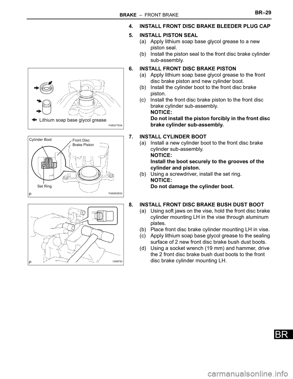
(a) Apply lithium soap base glycol grease to a new
piston seal.
(b) Install the piston seal to the front disc brake cylinder
sub-assembly.
6. INSTALL FRONT DISC BRAKE PISTON
(a) Apply lithium soap base glycol grease to the front
disc brake piston and new cylinder boot.
(b) Install the cylinder boot to the front disc brake
piston.
(c) Install the front disc brake piston to the front disc
brake cylinder sub-assembly.
NOTICE:
Do not install the piston forcibly in the front disc
brake cylinder sub-assembly.
7. INSTALL CYLINDER BOOT
(a) Install a new cylinder boot to the front disc brake
cylinder sub-assembly.
NOTICE:
Install the boot securely to the grooves of the
cylinder and piston.
(b) Using a screwdriver, install the set ring.
NOTICE:
Do not damage the cylinder boot.
8. INSTALL FRONT DISC BRAKE BUSH DUST BOOT
(a) Using soft jaws on the vise, hold the front disc brake
cylinder mounting LH in the vise through aluminum
plates.
(b) Place front disc brake cylinder mounting LH in vise.
(c) Apply lithium soap base glycol grease to the sealing
surface of 2 new front disc brake bush dust boots.
(d) Using a socket wrench (19 mm) and hammer, drive
the 2 front disc brake bush dust boots to the front
disc brake cylinder mounting LH.
F045277E04
F042832E03
C068792
Page 2617 of 3000
BRAKE – FRONT BRAKEBR–31
BR
7. REMOVE FRONT DISC BRAKE CYLINDER
ASSEMBLY LH
(a) Install the front disc brake cylinder sub-assembly
with the 2 bolts.
Torque: 34 N*m (350 kgf*cm, 25 ft.*lbf)
(b) Install a 2 new gaskets and flexible hose with the
union bolt.
Torque: 29 N*m (296 kgf*cm, 21 ft.*lbf)
HINT:
Install the flexible hose lock securely in the lock hole
in the disc brake cylinder.
8. FILL RESERVOIR WITH BRAKE FLUID (See page BR-
3)
9. BLEED BRAKE MASTER CYLINDER (See page BR-3)
10. BLEED BRAKE LINE (See page BR-4)
11. BLEED BRAKE ACTUATOR (w/ VSC) (See page BR-
4)
12. CHECK FLUID LEVEL IN RESERVOIR (See page BR-
7)
13. CHECK BRAKE FLUID LEAKAGE
14. INSTALL FRONT WHEEL
Torque: 103 N*m (1,050 kgf*cm, 76 ft.*lbf)
C097868
Page 2624 of 3000
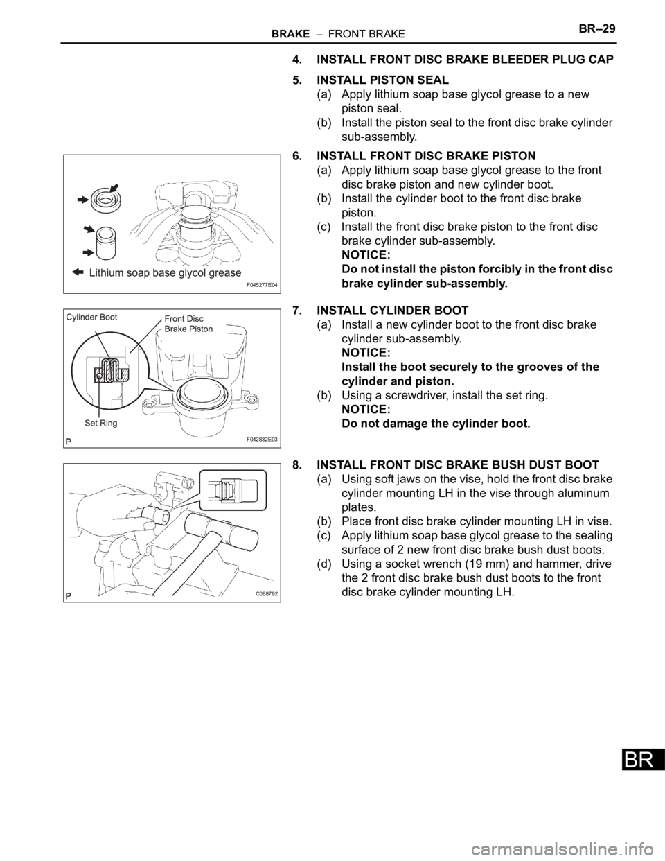
BRAKE – FRONT BRAKEBR–29
BR
4. INSTALL FRONT DISC BRAKE BLEEDER PLUG CAP
5. INSTALL PISTON SEAL
(a) Apply lithium soap base glycol grease to a new
piston seal.
(b) Install the piston seal to the front disc brake cylinder
sub-assembly.
6. INSTALL FRONT DISC BRAKE PISTON
(a) Apply lithium soap base glycol grease to the front
disc brake piston and new cylinder boot.
(b) Install the cylinder boot to the front disc brake
piston.
(c) Install the front disc brake piston to the front disc
brake cylinder sub-assembly.
NOTICE:
Do not install the piston forcibly in the front disc
brake cylinder sub-assembly.
7. INSTALL CYLINDER BOOT
(a) Install a new cylinder boot to the front disc brake
cylinder sub-assembly.
NOTICE:
Install the boot securely to the grooves of the
cylinder and piston.
(b) Using a screwdriver, install the set ring.
NOTICE:
Do not damage the cylinder boot.
8. INSTALL FRONT DISC BRAKE BUSH DUST BOOT
(a) Using soft jaws on the vise, hold the front disc brake
cylinder mounting LH in the vise through aluminum
plates.
(b) Place front disc brake cylinder mounting LH in vise.
(c) Apply lithium soap base glycol grease to the sealing
surface of 2 new front disc brake bush dust boots.
(d) Using a socket wrench (19 mm) and hammer, drive
the 2 front disc brake bush dust boots to the front
disc brake cylinder mounting LH.
F045277E04
F042832E03
C068792