Page 2699 of 3000

POWER STEERING – RACK AND PINION POWER STEERING GEARPS–31
PS
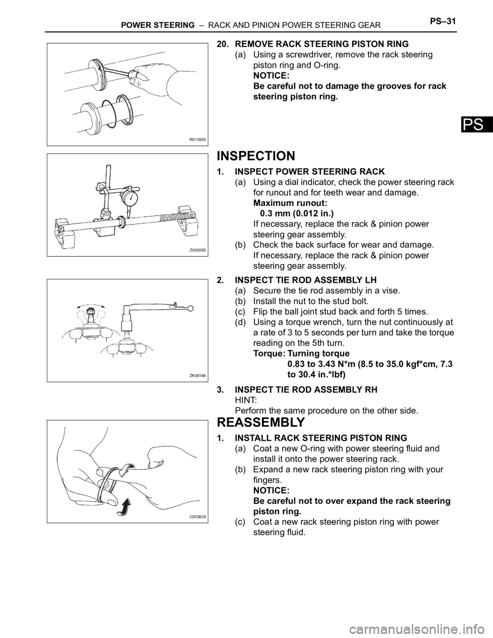
20. REMOVE RACK STEERING PISTON RING
(a) Using a screwdriver, remove the rack steering
piston ring and O-ring.
NOTICE:
Be careful not to damage the grooves for rack
steering piston ring.
INSPECTION
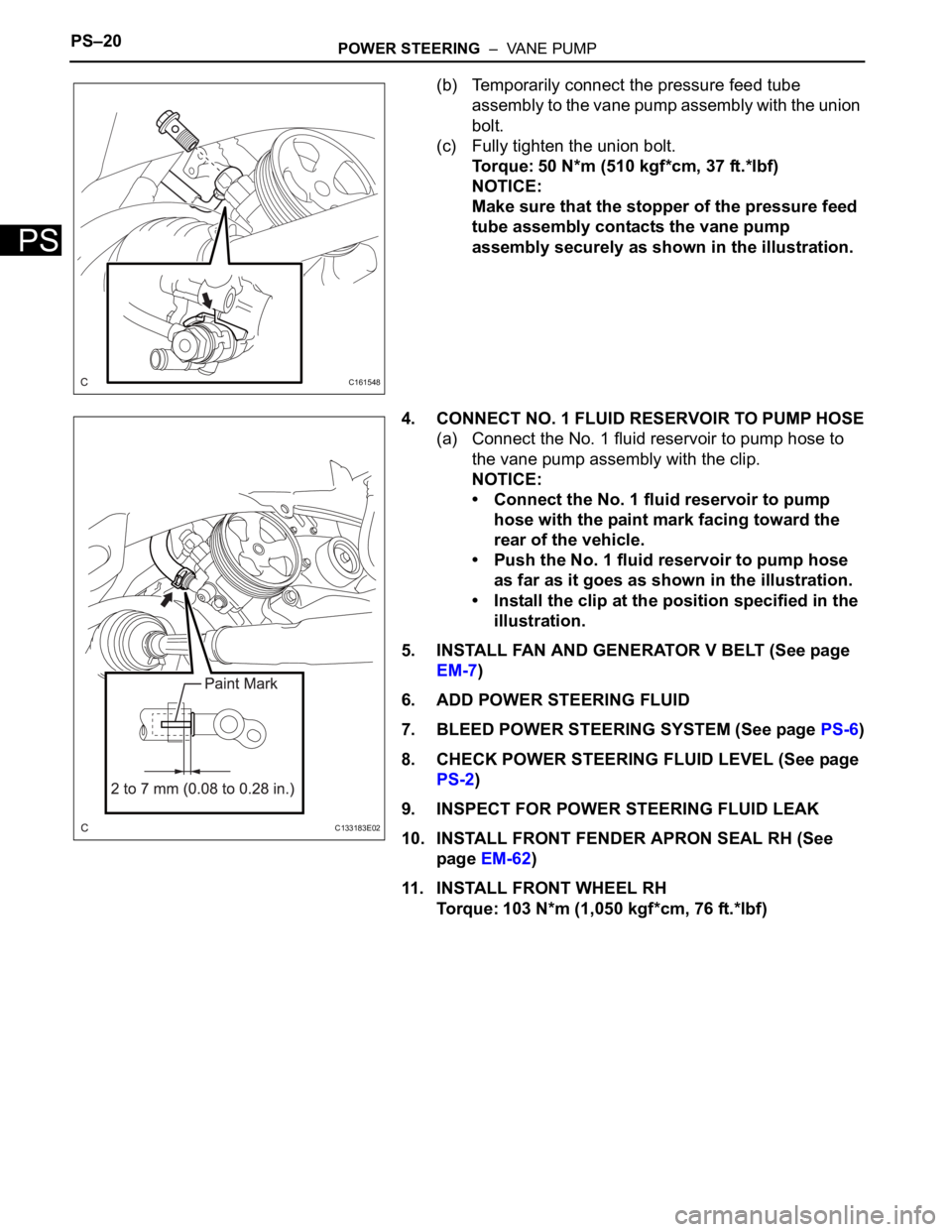
1. INSPECT POWER STEERING RACK
(a) Using a dial indicator, check the power steering rack
for runout and for teeth wear and damage.
Maximum runout:
0.3 mm (0.012 in.)
If necessary, replace the rack & pinion power
steering gear assembly.
(b) Check the back surface for wear and damage.
If necessary, replace the rack & pinion power
steering gear assembly.
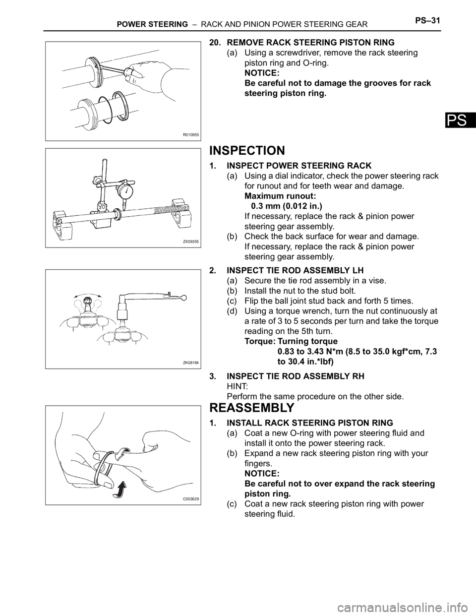
2. INSPECT TIE ROD ASSEMBLY LH
(a) Secure the tie rod assembly in a vise.
(b) Install the nut to the stud bolt.
(c) Flip the ball joint stud back and forth 5 times.
(d) Using a torque wrench, turn the nut continuously at
a rate of 3 to 5 seconds per turn and take the torque
reading on the 5th turn.
Torque: Turning torque
0.83 to 3.43 N*m (8.5 to 35.0 kgf*cm, 7.3
to 30.4 in.*lbf)
3. INSPECT TIE ROD ASSEMBLY RH
HINT:
Perform the same procedure on the other side.
REASSEMBLY
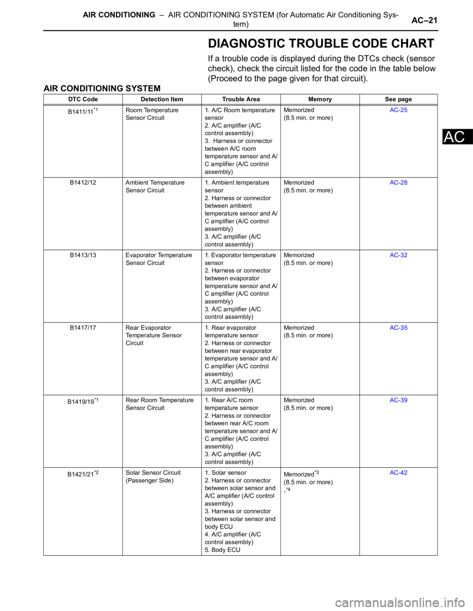
1. INSTALL RACK STEERING PISTON RING
(a) Coat a new O-ring with power steering fluid and
install it onto the power steering rack.
(b) Expand a new rack steering piston ring with your
fingers.
NOTICE:
Be careful not to over expand the rack steering
piston ring.
(c) Coat a new rack steering piston ring with power
steering fluid.
R010955
ZX09355
ZK08184
C003629
Page 2728 of 3000
POWER STEERING – VANE PUMPPS–17
PS
(c) Install the vane pump plates with the round end
facing outward.
NOTICE:
Make sure that the vane pump plates are
installed facing in the correct direction.
6. INSTALL VANE PUMP SHAFT SNAP RING
(a) Using a screwdriver and a snap ring expander,
install a new vane pump shaft snap ring onto the
vane pump shaft with pulley.
NOTICE:
Make sure that the vane pump shaft snap ring is
securely installed in the vane pump shaft
groove.
7. INSTALL VANE PUMP REAR HOUSING
(a) Coat a new O-ring with power steering fluid and
install it onto the vane pump rear housing.
(b) Align the straight pin of the vane pump rear housing
with the notches of the vane pump cam ring, vane
pump front side plate, and vane pump front housing.
C141370E01
D030336E01
C107040
C136780E01
Page 2731 of 3000

PS–20POWER STEERING – VANE PUMP
PS
(b) Temporarily connect the pressure feed tube
assembly to the vane pump assembly with the union
bolt.
(c) Fully tighten the union bolt.
Torque: 50 N*m (510 kgf*cm, 37 ft.*lbf)
NOTICE:
Make sure that the stopper of the pressure feed
tube assembly contacts the vane pump
assembly securely as shown in the illustration.
4. CONNECT NO. 1 FLUID RESERVOIR TO PUMP HOSE
(a) Connect the No. 1 fluid reservoir to pump hose to
the vane pump assembly with the clip.
NOTICE:
• Connect the No. 1 fluid reservoir to pump
hose with the paint mark facing toward the
rear of the vehicle.
• Push the No. 1 fluid reservoir to pump hose
as far as it goes as shown in the illustration.
• Install the clip at the position specified in the
illustration.
5. INSTALL FAN AND GENERATOR V BELT (See page
EM-7)
6. ADD POWER STEERING FLUID
7. BLEED POWER STEERING SYSTEM (See page PS-6)
8. CHECK POWER STEERING FLUID LEVEL (See page
PS-2)
9. INSPECT FOR POWER STEERING FLUID LEAK
10. INSTALL FRONT FENDER APRON SEAL RH (See
page EM-62)
11. INSTALL FRONT WHEEL RH
Torque: 103 N*m (1,050 kgf*cm, 76 ft.*lbf)
C161548
C133183E02
Page 2737 of 3000
PS–26POWER STEERING – RACK AND PINION POWER STEERING GEAR
PS
(d) Remove the nut and separate the tube clamp.
11. REMOVE RACK & PINION POWER STEERING GEAR
ASSEMBLY
(a) Remove the 2 bolts, nuts and the power steering
gear assembly.
NOTICE:
Do not damage the 2 pressure tubes.
DISASSEMBLY
1. REMOVE RETURN TUBE NO.2
(a) Using SST, remove the return tube No. 2.
SST 09023-12701
2. REMOVE STEERING LEFT TURN PRESSURE TUBE
(a) Using SST, remove the left turn pressure tube.
SST 09023-38201
(b) Remove the 2 O-rings from the left turn pressure
tube.
3. REMOVE STEERING RIGHT TURN PRESSURE TUBE
SST 09023-38201
HINT:
Perform the same procedure on the other side.
4. FIX RACK & PINION POWER STEERING GEAR
ASSEMBLY
(a) Using SST, secure the power steering gear
assembly.
SST 09612-00012
HINT:
Tape the SST before use.
D029975
D029979
D030600E01
D029981E01
D030616E01
Page 2739 of 3000
PS–28POWER STEERING – RACK AND PINION POWER STEERING GEAR
PS
(b) Using 2 SST, remove the 2 steering rack end sub-
assembly and 2 claw washers.
SST 09922-10010
NOTICE:
• Use SST 09922-10010 in the direction shown
in the illustration.
• Securely hold the power steering rack end
with a SST.
13. REMOVE RACK GUIDE
(a) Using SST, remove the rack guide spring cap nut.
SST 09922-10010
NOTICE:
Use SST 09922-10010in the direction shown in
the illustration.
(b) Using SST, remove the rack guide spring cap.
SST 09631-10021
(c) Remove the compression spring and the rack guide.
14. REMOVE POWER STEERING CONTROL VALVE
(a) Using a socket wrench (27 mm), remove the rack
housing cap.
F041526E01
F041500E01
F041501E01
F041502E01
Page 2742 of 3000

POWER STEERING – RACK AND PINION POWER STEERING GEARPS–31
PS
20. REMOVE RACK STEERING PISTON RING
(a) Using a screwdriver, remove the rack steering
piston ring and O-ring.
NOTICE:
Be careful not to damage the grooves for rack
steering piston ring.
INSPECTION
1. INSPECT POWER STEERING RACK
(a) Using a dial indicator, check the power steering rack
for runout and for teeth wear and damage.
Maximum runout:
0.3 mm (0.012 in.)
If necessary, replace the rack & pinion power
steering gear assembly.
(b) Check the back surface for wear and damage.
If necessary, replace the rack & pinion power
steering gear assembly.
2. INSPECT TIE ROD ASSEMBLY LH
(a) Secure the tie rod assembly in a vise.
(b) Install the nut to the stud bolt.
(c) Flip the ball joint stud back and forth 5 times.
(d) Using a torque wrench, turn the nut continuously at
a rate of 3 to 5 seconds per turn and take the torque
reading on the 5th turn.
Torque: Turning torque
0.83 to 3.43 N*m (8.5 to 35.0 kgf*cm, 7.3
to 30.4 in.*lbf)
3. INSPECT TIE ROD ASSEMBLY RH
HINT:
Perform the same procedure on the other side.
REASSEMBLY
1. INSTALL RACK STEERING PISTON RING
(a) Coat a new O-ring with power steering fluid and
install it onto the power steering rack.
(b) Expand a new rack steering piston ring with your
fingers.
NOTICE:
Be careful not to over expand the rack steering
piston ring.
(c) Coat a new rack steering piston ring with power
steering fluid.
R010955
ZX09355
ZK08184
C003629
Page 2755 of 3000
AIR CONDITIONING – AIR CONDITIONING SYSTEM (for Automatic Air Conditioning Sys-
tem)AC–7
AC
NEXT
NEXT
NEXT
NEXT
NEXT
9TERMINALS OF ECU
10CIRCUIT INSPECTION
11IDENTIFICATION OF PROBLEM
12REPAIR OR REPLACE
13CONFIRMATION TEST
END
Page 2767 of 3000

AIR CONDITIONING – AIR CONDITIONING SYSTEM (for Automatic Air Conditioning Sys-
tem)AC–21
AC
DIAGNOSTIC TROUBLE CODE CHART
If a trouble code is displayed during the DTCs check (sensor
check), check the circuit listed for the code in the table below
(Proceed to the page given for that circuit).
AIR CONDITIONING SYSTEM
DTC Code Detection Item Trouble Area Memory See page
B1411/11
*1Room Temperature
Sensor Circuit1. A/C Room temperature
sensor
2. A/C amplifier (A/C
control assembly)
3. Harness or connector
between A/C room
temperature sensor and A/
C amplifier (A/C control
assembly)Memorized
(8.5 min. or more)AC-25
B1412/12 Ambient Temperature
Sensor Circuit1. Ambient temperature
sensor
2. Harness or connector
between ambient
temperature sensor and A/
C amplifier (A/C control
assembly)
3. A/C amplifier (A/C
control assembly)Memorized
(8.5 min. or more)AC-28
B1413/13 Evaporator Temperature
Sensor Circuit1. Evaporator temperature
sensor
2. Harness or connector
between evaporator
temperature sensor and A/
C amplifier (A/C control
assembly)
3. A/C amplifier (A/C
control assembly)Memorized
(8.5 min. or more)AC-32
B1417/17 Rear Evaporator
Temperature Sensor
Circuit1. Rear evaporator
temperature sensor
2. Harness or connector
between rear evaporator
temperature sensor and A/
C amplifier (A/C control
assembly)
3. A/C amplifier (A/C
control assembly)Memorized
(8.5 min. or more)AC-35
B1419/19
*1Rear Room Temperature
Sensor Circuit1. Rear A/C room
temperature sensor
2. Harness or connector
between rear A/C room
temperature sensor and A/
C amplifier (A/C control
assembly)
3. A/C amplifier (A/C
control assembly)Memorized
(8.5 min. or more)AC-39
B1421/21
*2Solar Sensor Circuit
(Passenger Side)1. Solar sensor
2. Harness or connector
between solar sensor and
A/C amplifier (A/C control
assembly)
3. Harness or connector
between solar sensor and
body ECU
4. A/C amplifier (A/C
control assembly)
5. Body ECUMemorized*3
(8.5 min. or more)
-*4
AC-42