Page 2563 of 3000
BRAKE CONTROL – ANTI-LOCK BRAKE SYSTEMBC–29
BC
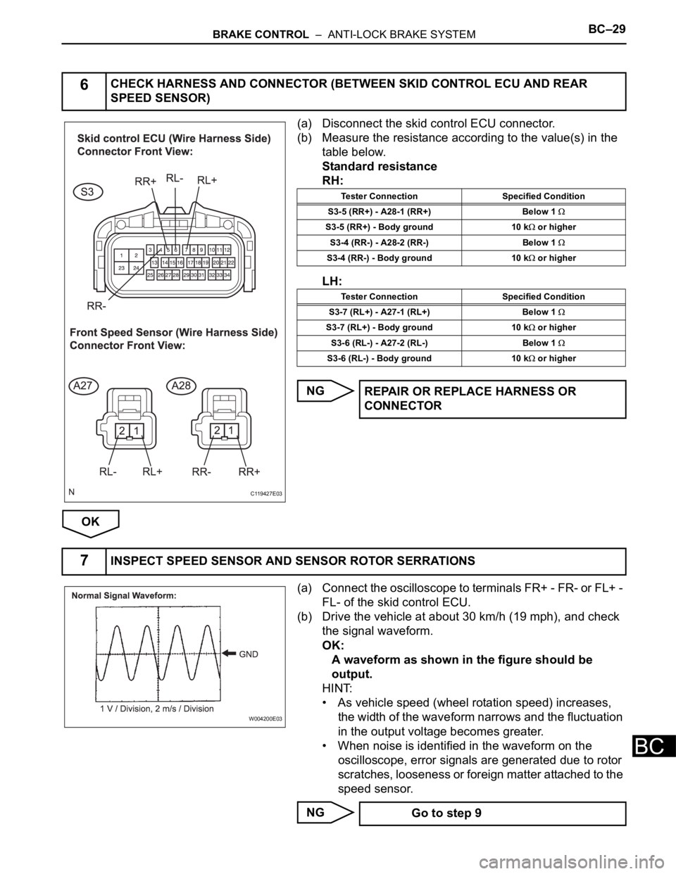
(a) Disconnect the skid control ECU connector.
(b) Measure the resistance according to the value(s) in the
table below.
Standard resistance
RH:
LH:
NG
OK
(a) Connect the oscilloscope to terminals FR+ - FR- or FL+ -
FL- of the skid control ECU.
(b) Drive the vehicle at about 30 km/h (19 mph), and check
the signal waveform.
OK:
A waveform as shown in the figure should be
output.
HINT:
• As vehicle speed (wheel rotation speed) increases,
the width of the waveform narrows and the fluctuation
in the output voltage becomes greater.
• When noise is identified in the waveform on the
oscilloscope, error signals are generated due to rotor
scratches, looseness or foreign matter attached to the
speed sensor.
NG
6CHECK HARNESS AND CONNECTOR (BETWEEN SKID CONTROL ECU AND REAR
SPEED SENSOR)
C119427E03
Tester Connection Specified Condition
S3-5 (RR+) - A28-1 (RR+) Below 1
S3-5 (RR+) - Body ground 10 k or higher
S3-4 (RR-) - A28-2 (RR-) Below 1
S3-4 (RR-) - Body ground 10 k or higher
Tester Connection Specified Condition
S3-7 (RL+) - A27-1 (RL+) Below 1
S3-7 (RL+) - Body ground 10 k or higher
S3-6 (RL-) - A27-2 (RL-) Below 1
S3-6 (RL-) - Body ground 10 k or higher
REPAIR OR REPLACE HARNESS OR
CONNECTOR
7INSPECT SPEED SENSOR AND SENSOR ROTOR SERRATIONS
W004200E03
Go to step 9
Page 2567 of 3000
BRAKE CONTROL – ANTI-LOCK BRAKE SYSTEMBC–31
BC
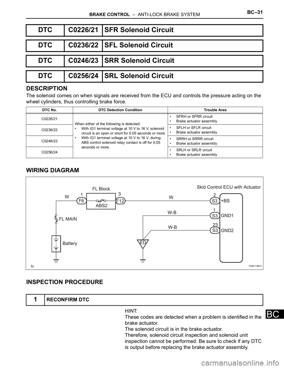
DESCRIPTION
The solenoid comes on when signals are received from the ECU and controls the pressure acting on the
wheel cylinders, thus controlling brake force.
WIRING DIAGRAM
INSPECTION PROCEDURE
HINT:
These codes are detected when a problem is identified in the
brake actuator.
The solenoid circuit is in the brake actuator.
Therefore, solenoid circuit inspection and solenoid unit
inspection cannot be performed. Be sure to check if any DTC
is output before replacing the brake actuator assembly.
DTC C0226/21 SFR Solenoid Circuit
DTC C0236/22 SFL Solenoid Circuit
DTC C0246/23 SRR Solenoid Circuit
DTC C0256/24 SRL Solenoid Circuit
DTC No. DTC Detection Condition Trouble Area
C0226/21
When either of the following is detected:
• With IG1 terminal voltage at 10 V to 16 V, solenoid
circuit is an open or short for 0.05 seconds or more.
• With IG1 terminal voltage at 10 V to 16 V, during
ABS control solenoid relay contact is off for 0.05
seconds or more.• SFRH or SFRR circuit
• Brake actuator assembly
C0236/22• SFLH or SFLR circuit
• Brake actuator assembly
C0246/23• SRRH or SRRR circuit
• Brake actuator assembly
C0256/24• SRLH or SRLR circuit
• Brake actuator assembly
1RECONFIRM DTC
F045115E01
Page 2568 of 3000
BC–32BRAKE CONTROL – ANTI-LOCK BRAKE SYSTEM
BC
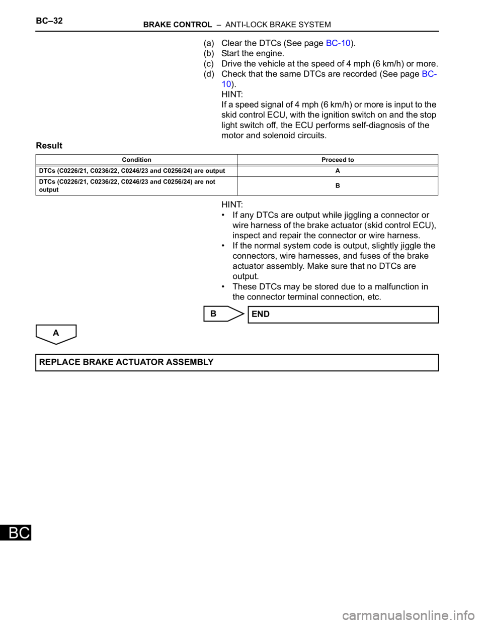
(a) Clear the DTCs (See page BC-10).
(b) Start the engine.
(c) Drive the vehicle at the speed of 4 mph (6 km/h) or more.
(d) Check that the same DTCs are recorded (See page BC-
10).
HINT:
If a speed signal of 4 mph (6 km/h) or more is input to the
skid control ECU, with the ignition switch on and the stop
light switch off, the ECU performs self-diagnosis of the
motor and solenoid circuits.
Result
HINT:
• If any DTCs are output while jiggling a connector or
wire harness of the brake actuator (skid control ECU),
inspect and repair the connector or wire harness.
• If the normal system code is output, slightly jiggle the
connectors, wire harnesses, and fuses of the brake
actuator assembly. Make sure that no DTCs are
output.
• These DTCs may be stored due to a malfunction in
the connector terminal connection, etc.
B
A
Condition Proceed to
DTCs (C0226/21, C0236/22, C0246/23 and C0256/24) are output A
DTCs (C0226/21, C0236/22, C0246/23 and C0256/24) are not
outputB
END
REPLACE BRAKE ACTUATOR ASSEMBLY
Page 2571 of 3000
BRAKE CONTROL – ANTI-LOCK BRAKE SYSTEMBC–33
BC
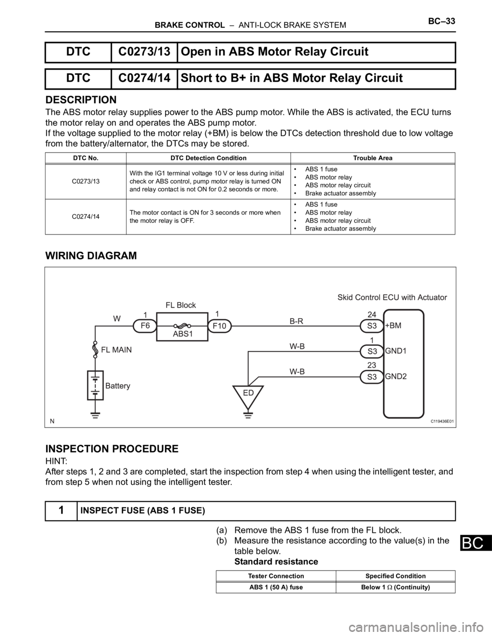
DESCRIPTION
The ABS motor relay supplies power to the ABS pump motor. While the ABS is activated, the ECU turns
the motor relay on and operates the ABS pump motor.
If the voltage supplied to the motor relay (+BM) is below the DTCs detection threshold due to low voltage
from the battery/alternator, the DTCs may be stored.
WIRING DIAGRAM
INSPECTION PROCEDURE
HINT:
After steps 1, 2 and 3 are completed, start the inspection from step 4 when using the intelligent tester, and
from step 5 when not using the intelligent tester.
(a) Remove the ABS 1 fuse from the FL block.
(b) Measure the resistance according to the value(s) in the
table below.
Standard resistance
DTC C0273/13 Open in ABS Motor Relay Circuit
DTC C0274/14 Short to B+ in ABS Motor Relay Circuit
DTC No. DTC Detection Condition Trouble Area
C0273/13With the IG1 terminal voltage 10 V or less during initial
check or ABS control, pump motor relay is turned ON
and relay contact is not ON for 0.2 seconds or more.• ABS 1 fuse
• ABS motor relay
• ABS motor relay circuit
• Brake actuator assembly
C0274/14The motor contact is ON for 3 seconds or more when
the motor relay is OFF.• ABS 1 fuse
• ABS motor relay
• ABS motor relay circuit
• Brake actuator assembly
1INSPECT FUSE (ABS 1 FUSE)
C119436E01
Tester Connection Specified Condition
ABS 1 (50 A) fuse Below 1
(Continuity)
Page 2572 of 3000
BC–34BRAKE CONTROL – ANTI-LOCK BRAKE SYSTEM
BC
NG
OK
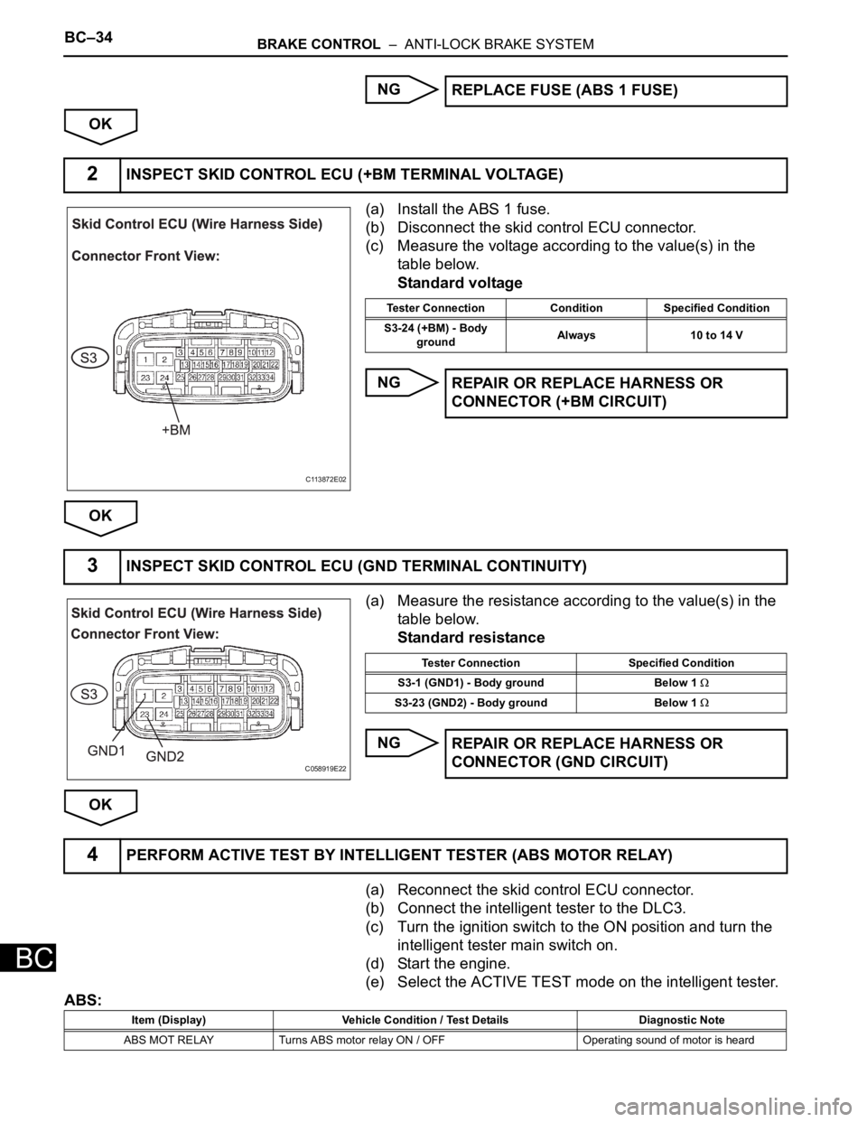
(a) Install the ABS 1 fuse.
(b) Disconnect the skid control ECU connector.
(c) Measure the voltage according to the value(s) in the
table below.
Standard voltage
NG
OK
(a) Measure the resistance according to the value(s) in the
table below.
Standard resistance
NG
OK
(a) Reconnect the skid control ECU connector.
(b) Connect the intelligent tester to the DLC3.
(c) Turn the ignition switch to the ON position and turn the
intelligent tester main switch on.
(d) Start the engine.
(e) Select the ACTIVE TEST mode on the intelligent tester.
ABS:REPLACE FUSE (ABS 1 FUSE)
2INSPECT SKID CONTROL ECU (+BM TERMINAL VOLTAGE)
C113872E02
Tester Connection Condition Specified Condition
S3-24 (+BM) - Body
groundAlways 10 to 14 V
REPAIR OR REPLACE HARNESS OR
CONNECTOR (+BM CIRCUIT)
3INSPECT SKID CONTROL ECU (GND TERMINAL CONTINUITY)
C058919E22
Tester Connection Specified Condition
S3-1 (GND1) - Body ground Below 1
S3-23 (GND2) - Body ground Below 1
REPAIR OR REPLACE HARNESS OR
CONNECTOR (GND CIRCUIT)
4PERFORM ACTIVE TEST BY INTELLIGENT TESTER (ABS MOTOR RELAY)
Item (Display) Vehicle Condition / Test Details Diagnostic Note
ABS MOT RELAY Turns ABS motor relay ON / OFF Operating sound of motor is heard
Page 2573 of 3000
BRAKE CONTROL – ANTI-LOCK BRAKE SYSTEMBC–35
BC
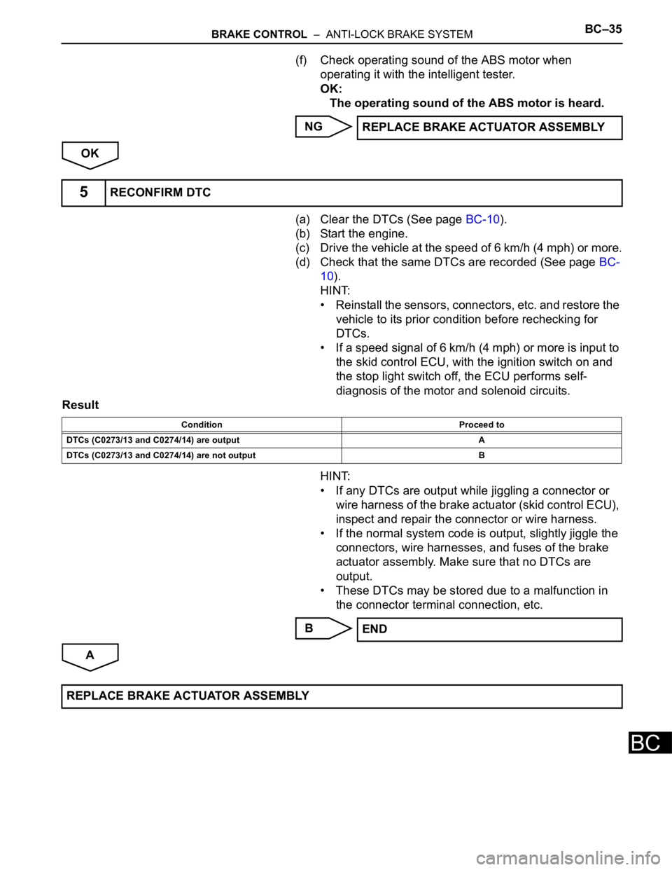
(f) Check operating sound of the ABS motor when
operating it with the intelligent tester.
OK:
The operating sound of the ABS motor is heard.
NG
OK
(a) Clear the DTCs (See page BC-10).
(b) Start the engine.
(c) Drive the vehicle at the speed of 6 km/h (4 mph) or more.
(d) Check that the same DTCs are recorded (See page BC-
10).
HINT:
• Reinstall the sensors, connectors, etc. and restore the
vehicle to its prior condition before rechecking for
DTCs.
• If a speed signal of 6 km/h (4 mph) or more is input to
the skid control ECU, with the ignition switch on and
the stop light switch off, the ECU performs self-
diagnosis of the motor and solenoid circuits.
Result
HINT:
• If any DTCs are output while jiggling a connector or
wire harness of the brake actuator (skid control ECU),
inspect and repair the connector or wire harness.
• If the normal system code is output, slightly jiggle the
connectors, wire harnesses, and fuses of the brake
actuator assembly. Make sure that no DTCs are
output.
• These DTCs may be stored due to a malfunction in
the connector terminal connection, etc.
B
AREPLACE BRAKE ACTUATOR ASSEMBLY
5RECONFIRM DTC
Condition Proceed to
DTCs (C0273/13 and C0274/14) are output A
DTCs (C0273/13 and C0274/14) are not output B
END
REPLACE BRAKE ACTUATOR ASSEMBLY
Page 2577 of 3000
BRAKE CONTROL – ANTI-LOCK BRAKE SYSTEMBC–37
BC
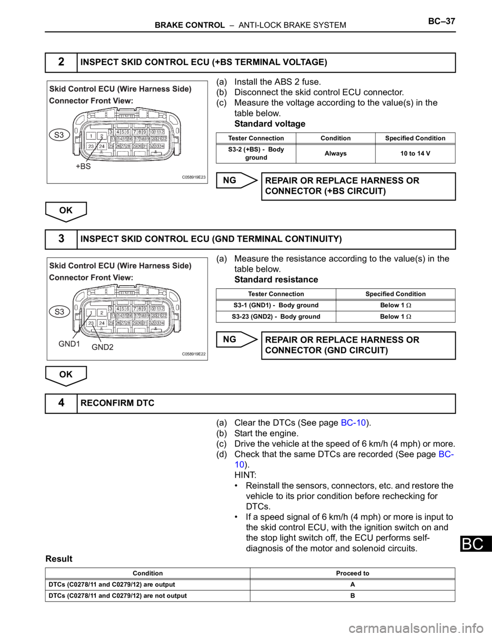
(a) Install the ABS 2 fuse.
(b) Disconnect the skid control ECU connector.
(c) Measure the voltage according to the value(s) in the
table below.
Standard voltage
NG
OK
(a) Measure the resistance according to the value(s) in the
table below.
Standard resistance
NG
OK
(a) Clear the DTCs (See page BC-10).
(b) Start the engine.
(c) Drive the vehicle at the speed of 6 km/h (4 mph) or more.
(d) Check that the same DTCs are recorded (See page BC-
10).
HINT:
• Reinstall the sensors, connectors, etc. and restore the
vehicle to its prior condition before rechecking for
DTCs.
• If a speed signal of 6 km/h (4 mph) or more is input to
the skid control ECU, with the ignition switch on and
the stop light switch off, the ECU performs self-
diagnosis of the motor and solenoid circuits.
Result
2INSPECT SKID CONTROL ECU (+BS TERMINAL VOLTAGE)
C058919E23
Tester Connection Condition Specified Condition
S3-2 (+BS) - Body
groundAlways 10 to 14 V
REPAIR OR REPLACE HARNESS OR
CONNECTOR (+BS CIRCUIT)
3INSPECT SKID CONTROL ECU (GND TERMINAL CONTINUITY)
C058919E22
Tester Connection Specified Condition
S3-1 (GND1) - Body ground Below 1
S3-23 (GND2) - Body ground Below 1
REPAIR OR REPLACE HARNESS OR
CONNECTOR (GND CIRCUIT)
4RECONFIRM DTC
Condition Proceed to
DTCs (C0278/11 and C0279/12) are output A
DTCs (C0278/11 and C0279/12) are not output B
Page 2578 of 3000
BC–38BRAKE CONTROL – ANTI-LOCK BRAKE SYSTEM
BC
HINT:
• If any DTCs are output while jiggling a connector or
wire harness of the brake actuator (skid control ECU),
inspect and repair the connector or wire harness.
• If the normal system code is output, slightly jiggle the
connectors, wire harnesses, and fuses of the brake
actuator assembly. Make sure that no DTCs are
output.
• These DTCs may be memorized due to a malfunction
in the connector terminal connection, etc.
B
AEND
REPLACE BRAKE ACTUATOR ASSEMBLY