Page 486 of 3000

ES–1802GR-FE ENGINE CONTROL SYSTEM – SFI SYSTEM
ES
OK
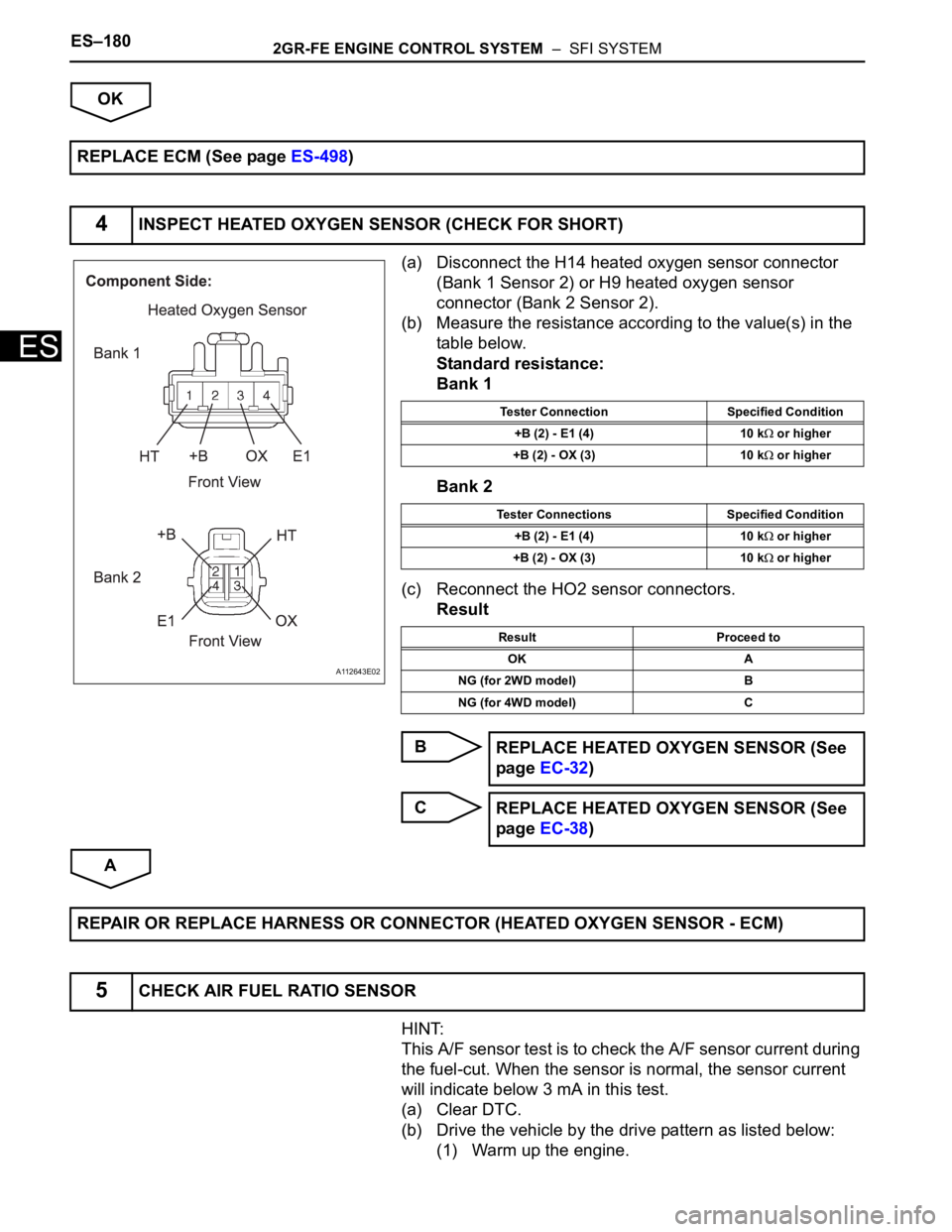
(a) Disconnect the H14 heated oxygen sensor connector
(Bank 1 Sensor 2) or H9 heated oxygen sensor
connector (Bank 2 Sensor 2).
(b) Measure the resistance according to the value(s) in the
table below.
Standard resistance:
Bank 1
Bank 2
(c) Reconnect the HO2 sensor connectors.
Result
B
C
A
HINT:
This A/F sensor test is to check the A/F sensor current during
the fuel-cut. When the sensor is normal, the sensor current
will indicate below 3 mA in this test.
(a) Clear DTC.
(b) Drive the vehicle by the drive pattern as listed below:
(1) Warm up the engine. REPLACE ECM (See page ES-498)
4INSPECT HEATED OXYGEN SENSOR (CHECK FOR SHORT)
A112643E02
Tester Connection Specified Condition
+B (2) - E1 (4) 10 k
or higher
+B (2) - OX (3) 10 k
or higher
Tester Connections Specified Condition
+B (2) - E1 (4) 10 k
or higher
+B (2) - OX (3) 10 k
or higher
Result Proceed to
OK A
NG (for 2WD model) B
NG (for 4WD model) C
REPLACE HEATED OXYGEN SENSOR (See
page EC-32)
REPLACE HEATED OXYGEN SENSOR (See
page EC-38)
REPAIR OR REPLACE HARNESS OR CONNECTOR (HEATED OXYGEN SENSOR - ECM)
5CHECK AIR FUEL RATIO SENSOR
Page 491 of 3000

2GR-FE ENGINE CONTROL SYSTEM – SFI SYSTEMES–185
ES
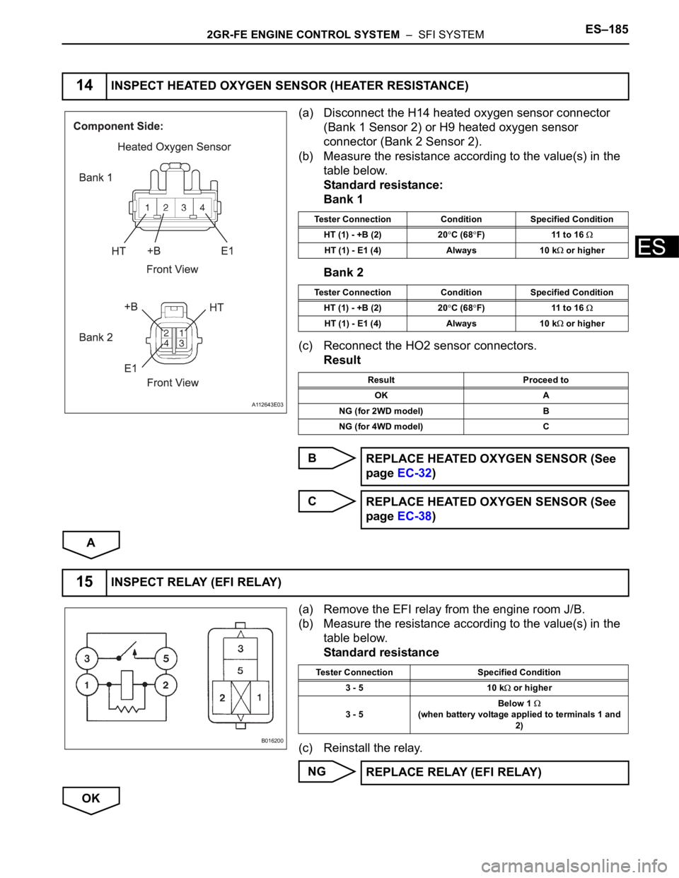
(a) Disconnect the H14 heated oxygen sensor connector
(Bank 1 Sensor 2) or H9 heated oxygen sensor
connector (Bank 2 Sensor 2).
(b) Measure the resistance according to the value(s) in the
table below.
Standard resistance:
Bank 1
Bank 2
(c) Reconnect the HO2 sensor connectors.
Result
B
C
A
(a) Remove the EFI relay from the engine room J/B.
(b) Measure the resistance according to the value(s) in the
table below.
Standard resistance
(c) Reinstall the relay.
NG
OK
14INSPECT HEATED OXYGEN SENSOR (HEATER RESISTANCE)
A112643E03
Tester Connection Condition Specified Condition
HT (1) - +B (2) 20
C (68F) 11 to 16
HT (1) - E1 (4) Always 10 k or higher
Tester Connection Condition Specified Condition
HT (1) - +B (2) 20
C (68F) 11 to 16
HT (1) - E1 (4) Always 10 k or higher
Result Proceed to
OK A
NG (for 2WD model) B
NG (for 4WD model) C
REPLACE HEATED OXYGEN SENSOR (See
page EC-32)
REPLACE HEATED OXYGEN SENSOR (See
page EC-38)
15INSPECT RELAY (EFI RELAY)
B016200
Tester Connection Specified Condition
3 - 5 10 k
or higher
3 - 5Below 1
(when battery voltage applied to terminals 1 and
2)
REPLACE RELAY (EFI RELAY)
Page 502 of 3000

ES–1962GR-FE ENGINE CONTROL SYSTEM – SFI SYSTEM
ES
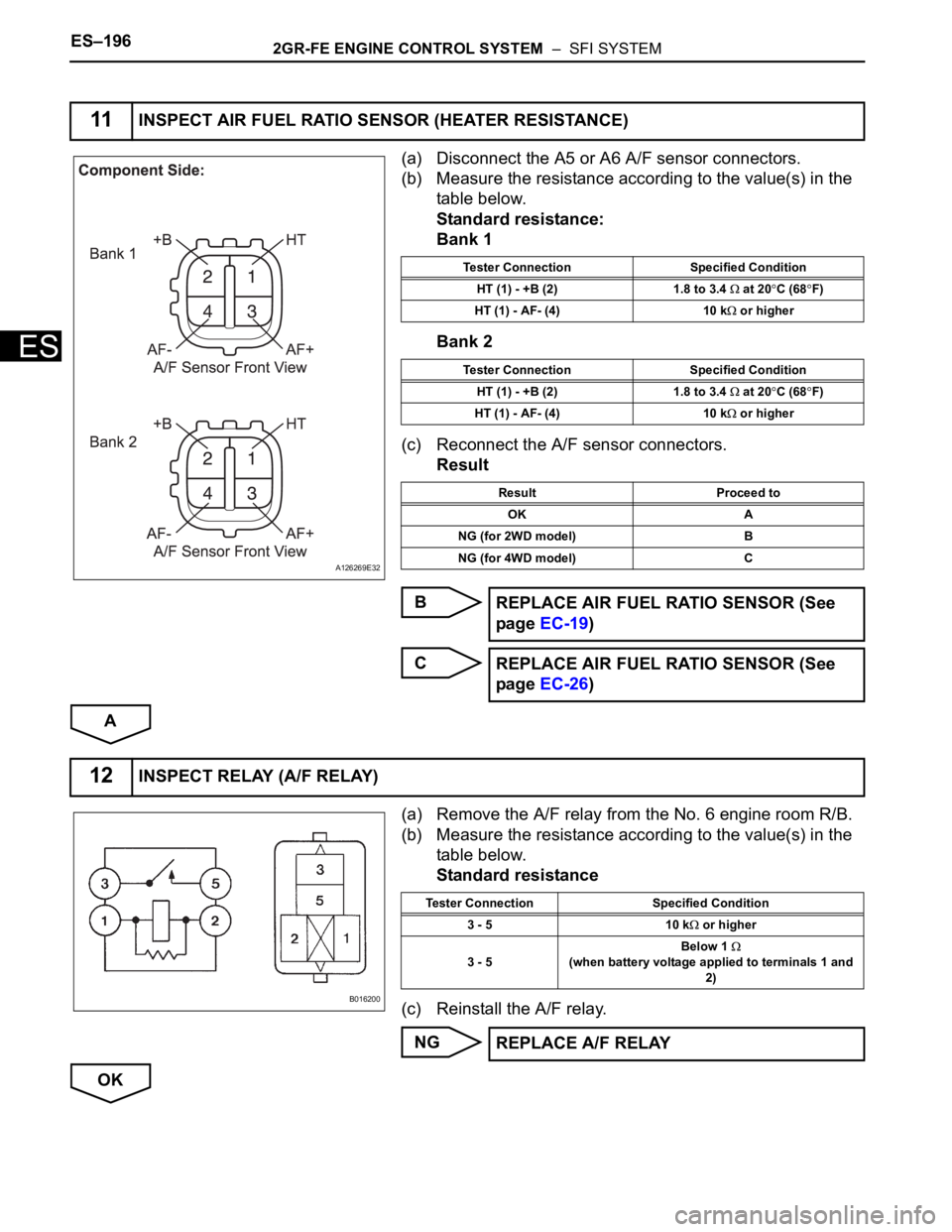
(a) Disconnect the A5 or A6 A/F sensor connectors.
(b) Measure the resistance according to the value(s) in the
table below.
Standard resistance:
Bank 1
Bank 2
(c) Reconnect the A/F sensor connectors.
Result
B
C
A
(a) Remove the A/F relay from the No. 6 engine room R/B.
(b) Measure the resistance according to the value(s) in the
table below.
Standard resistance
(c) Reinstall the A/F relay.
NG
OK
11INSPECT AIR FUEL RATIO SENSOR (HEATER RESISTANCE)
A126269E32
Tester Connection Specified Condition
HT (1) - +B (2) 1.8 to 3.4
at 20C (68F)
HT (1) - AF- (4) 10 k
or higher
Tester Connection Specified Condition
HT (1) - +B (2) 1.8 to 3.4
at 20C (68F)
HT (1) - AF- (4) 10 k
or higher
Result Proceed to
OK A
NG (for 2WD model) B
NG (for 4WD model) C
REPLACE AIR FUEL RATIO SENSOR (See
page EC-19)
REPLACE AIR FUEL RATIO SENSOR (See
page EC-26)
12INSPECT RELAY (A/F RELAY)
B016200
Tester Connection Specified Condition
3 - 5 10 k
or higher
3 - 5Below 1
(when battery voltage applied to terminals 1 and
2)
REPLACE A/F RELAY
Page 513 of 3000
2GR-FE ENGINE CONTROL SYSTEM – SFI SYSTEMES–207
ES
CONFIRMATION DRIVING PATTERN
1. Connect the intelligent tester to the DLC3.
2. Turn the ignition switch to the ON position.
3. Turn the tester on.
4. Record the DTC(s) and freeze frame data.
5. Using the tester, switch the ECM from normal mode to check mode (See page ES-43).
6. Read the misfire counts of each cylinder (CYL #1 to #6) with the engine in an idling condition. If any
misfire count is displayed, skip the following confirmation driving pattern.
A162495E02
Page 514 of 3000

ES–2082GR-FE ENGINE CONTROL SYSTEM – SFI SYSTEM
ES
7. Drive the vehicle several times with the conditions, such as engine rpm and engine load, shown in
MISFIRE RPM and MISFIRE LOAD in the Data List.
HINT:
• In order to store misfire DTCs, it is necessary to operate the vehicle for the period of time shown in
the table below, using the MISFIRE RPM and MISFIRE LOAD in the Data List.
8. Check whether misfires have occurred by checking DTCs and freeze frame data.
HINT:
Do not turn the ignition switch off until the stored DTC(s) and freeze frame data have been recorded.
When the ECM returns to normal mode (default), the stored DTC(s), freeze frame data and other data
will be erased.
9. Record the DTC(s), freeze frame data and misfire counts.
10.Turn the ignition switch OFF and wait for at least 5 seconds.
INSPECTION PROCEDURE
HINT:
• If any DTCs other than misfire DTCs are output, troubleshoot those DTCs first.
• Read freeze frame data using the intelligent tester or Techstream. Freeze frame data records the
engine condition when malfunctions are detected. When troubleshooting, freeze frame data can help
determine if the vehicle was moving or stationary, if the engine was warmed up or not, if the air-fuel
ratio was lean or rich, and other data from the time the malfunction occurred.
• If the misfire does not recur when the vehicle is brought to the workshop, reproduce the conditions
stored in the ECM as freeze frame data.
• If the misfire still cannot be reproduced even though the conditions stored in the ECM as freeze frame
data have been reproduced, one of the following factors is considered to be a possible cause of the
problem:
(a) There was insufficient fuel volume in the tank.
(b) Improper fuel is used.
(c) The spark plugs have been contaminated.
• After finishing repairs, check the misfire counts of the cylinders (CYL #1, #2, #3, #4, #5, #6).
• Be sure to confirm that no misfiring cylinder DTCs are set again by conducting the confirmation driving
pattern after finishing repairs.
• For 6 and 8 cylinder engines, the ECM intentionally does not set the specific misfiring cylinder DTCs at
high engine RPM. If misfires occur only in high engine RPM areas, only DTC P0300 is set.
In the event of DTC P0300 being present, perform the following operations:
(a) Clear the DTC (See page ES-39).
(b) Start the engine and conduct the confirmation driving pattern.
(c) Read the misfiring rates of each cylinder or DTC(s) using the tester.
(d) Repair the cylinder(s) that has a high misfiring rate or is indicated by the DTC.
(e) After finishing repairs, conduct the confirmation driving pattern again, in order to verify that DTC
P0300 is not set.
• When one of SHORT FT #1, LONG FT #1, SHORT FT #2 or LONG FT #2 in the freeze frame data is
outside the range of +/-20%, the air-fuel ratio may be Rich (-20% or less) or Lean (+20% or more).
• When the COOLANT TEMP in the freeze frame data is less than 75
C (167F), the misfire have
occurred only while warming up the engine.
Engine RPM Duration
Idling 3.5 minutes or more
1000 3 minutes or more
2000 1.5 minutes or more
3000 1 minute or more
Page 602 of 3000
2GR-FE ENGINE CONTROL SYSTEM – SFI SYSTEMES–309
ES
NOTICE:
In this operation, the engine must be cold (the same level
as the engine coolant temperature recorded in the freeze
frame data).
(a) Connect the intelligent tester to the DLC3.
(b) Turn the ignition switch to the ON position.
(c) Turn the tester on.
(d) Clear the DTCs (See page ES-39).
(e) Switch the ECM from normal mode to check mode using
the tester (See page ES-43).
(f) Start the engine to idle for a minute.
OK:
Stable fast idling.
(g) Read the DTCs.
OK:
No DTC output.
NEXT
15CHECK WHETHER DTC OUTPUT RECURS (DTC P050A)
END
Page 608 of 3000
2GR-FE ENGINE CONTROL SYSTEM – SFI SYSTEMES–315
ES
NEXT
NOTICE:
In this operation, the engine must be cold (the same level
as the engine coolant temperature recorded in the freeze
frame data).
(a) Connect the intelligent tester to the DLC3.
(b) Turn the ignition switch to the ON position.
(c) Turn the tester on.
(d) Clear the DTCs.
(e) Switch the ECM from normal mode to check mode using
the tester.
(f) Start the engine to idle for a minute.
OK:
Stable fast idling.
(g) Read the DTCs.
OK:
No DTC output.
NEXT
14REPAIR OR REPLACE THROTTLE BODY ASSEMBLY
Go to step 15
15CHECK WHETHER DTC OUTPUT RECURS (DTC P050B)
END
Page 616 of 3000

2GR-FE ENGINE CONTROL SYSTEM – SFI SYSTEMES–323
ES
OK
(a) Connect the intelligent tester to the DLC3.
(b) Start the engine and turn the tester on.
(c) Warm up the engine at an engine speed of 2500rpm for
approximately 90 seconds.
(d) Enter the following menus: DIAGNOSIS / ENHANCED II
/ ACTIVE TEST / A/F CONTROL.
(e) Perform the A/F CONTROL operation with the engine in
an idling condition (press the RIGHT or LEFT button to
change the fuel injection volume).
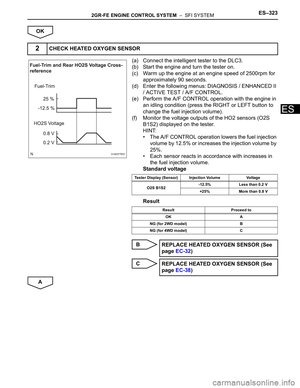
(f) Monitor the voltage outputs of the HO2 sensors (O2S
B1S2) displayed on the tester.
HINT:
• The A/F CONTROL operation lowers the fuel injection
volume by 12.5% or increases the injection volume by
25%.
• Each sensor reacts in accordance with increases in
the fuel injection volume.
Standard voltage
Result
B
C
A
2CHECK HEATED OXYGEN SENSOR
A142077E01
Tester Display (Sensor) Injection Volume Voltage
O2S B1S2-12.5% Less than 0.2 V
+25% More than 0.8 V
Result Proceed to
OK A
NG (for 2WD model) B
NG (for 4WD model) C
REPLACE HEATED OXYGEN SENSOR (See
page EC-32)
REPLACE HEATED OXYGEN SENSOR (See
page EC-38)