Page 2192 of 3000
SUSPENSION – REAR WHEEL ALIGNMENTSP–9
SP
REAR WHEEL ALIGNMENT
ADJUSTMENT
NOTICE:
For vehicles equipped with VSC, if wheel alignment has
been adjusted, and if suspension or underbody
components have been removed/installed or replaced, be
sure to perform the following initialization procedure in
order for the system to function normally:
1. Disconnect the negative battery terminal for more
than 2 seconds.
2. Reconnect the negative battery terminal.
3. Perform zero point calibration of the yaw rate and
acceleration sensor and test mode inspection.
HINT:
(See page BC-70)
1. INSPECT TIRE
HINT:
(See page TW-2)
2. MEASURE VEHICLE HEIGHT
NOTICE:
Before inspecting the wheel alignment, adjust the
vehicle height to the specified valve.
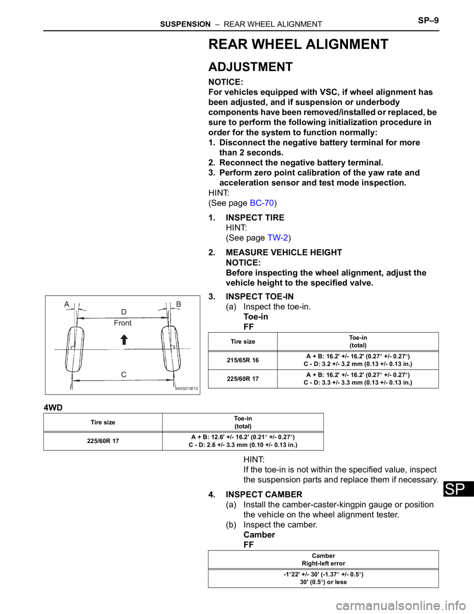
3. INSPECT TOE-IN
(a) Inspect the toe-in.
To e - i n
FF
4WD
HINT:
If the toe-in is not within the specified value, inspect
the suspension parts and replace them if necessary.
4. INSPECT CAMBER
(a) Install the camber-caster-kingpin gauge or position
the vehicle on the wheel alignment tester.
(b) Inspect the camber.
Camber
FF
SA03213E12
Tire sizeTo e - i n
(total)
215/65R 16A + B: 16.2' +/- 16.2' (0.27
+/- 0.27)
C - D: 3.2 +/- 3.2 mm (0.13 +/- 0.13 in.)
225/60R 17A + B: 16.2' +/- 16.2' (0.27
+/- 0.27)
C - D: 3.3 +/- 3.3 mm (0.13 +/- 0.13 in.)
Tire sizeTo e - i n
(total)
225/60R 17A + B: 12.6' +/- 16.2' (0.21
+/- 0.27)
C - D: 2.6 +/- 3.3 mm (0.10 +/- 0.13 in.)
Camber
Right-left error
-1
22' +/- 30' (-1.37 +/- 0.5)
30' (0.5
) or less
Page 2275 of 3000
TW–28TIRE AND WHEEL – TIRE PRESSURE WARNING SYSTEM
TW
TEST MODE PROCEDURE
1. ENTER TEST MODE
HINT:
• Operation of the tire pressure warning reset switch
can be checked in TEST MODE.
• During TEST MODE, the system is not initialized by
pushing the tire pressure warning reset switch. The
circuit of the tire pressure warning reset switch can be
inspected during this mode.
(a) Make sure that the ignition switch is off.
(b) Connect the intelligent tester to DLC3.
(c) Turn the ignition switch to the ON position.
(d) Check that the tire pressure warning light comes on
for 3 seconds and then goes off.
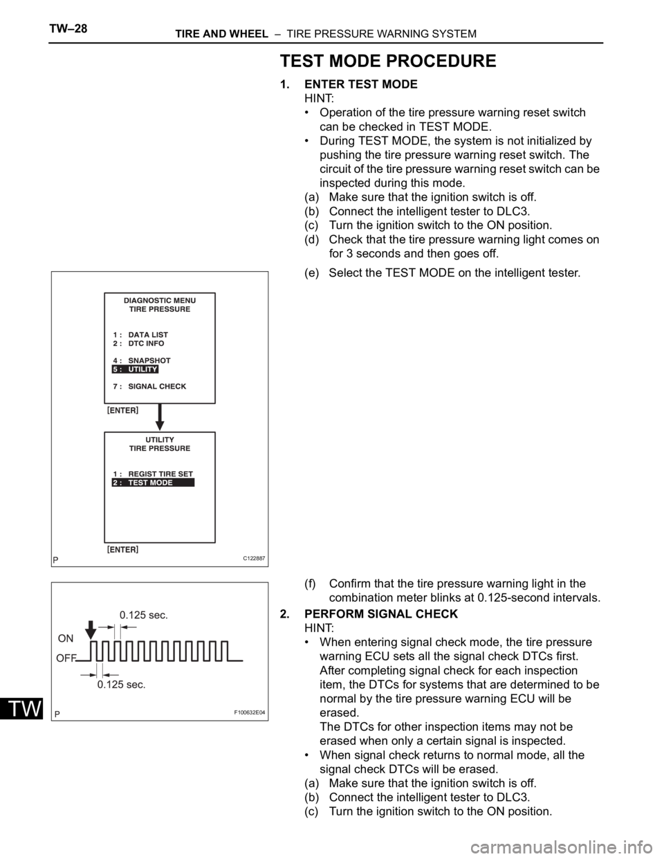
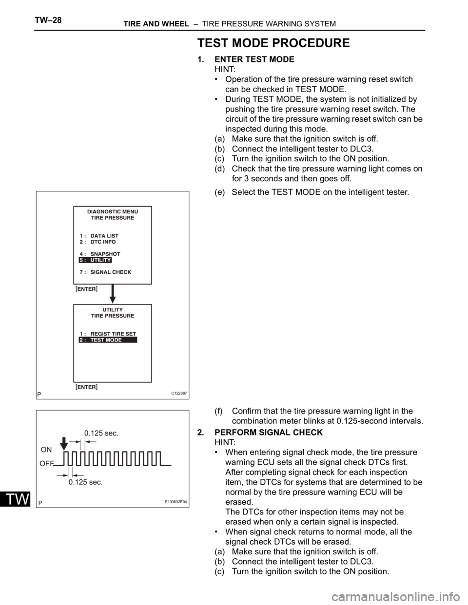
(e) Select the TEST MODE on the intelligent tester.
(f) Confirm that the tire pressure warning light in the
combination meter blinks at 0.125-second intervals.
2. PERFORM SIGNAL CHECK
HINT:
• When entering signal check mode, the tire pressure
warning ECU sets all the signal check DTCs first.
After completing signal check for each inspection
item, the DTCs for systems that are determined to be
normal by the tire pressure warning ECU will be
erased.
The DTCs for other inspection items may not be
erased when only a certain signal is inspected.
• When signal check returns to normal mode, all the
signal check DTCs will be erased.
(a) Make sure that the ignition switch is off.
(b) Connect the intelligent tester to DLC3.
(c) Turn the ignition switch to the ON position.
C122887
F100632E04
Page 2276 of 3000
TIRE AND WHEEL – TIRE PRESSURE WARNING SYSTEMTW–29
TW
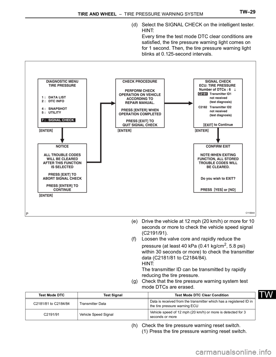
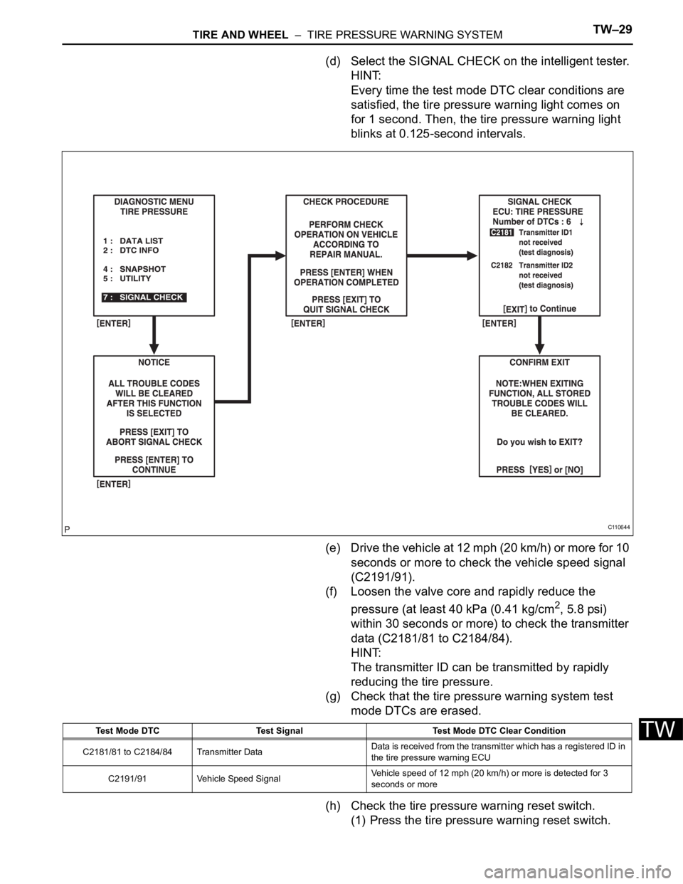
(d) Select the SIGNAL CHECK on the intelligent tester.
HINT:
Every time the test mode DTC clear conditions are
satisfied, the tire pressure warning light comes on
for 1 second. Then, the tire pressure warning light
blinks at 0.125-second intervals.
(e) Drive the vehicle at 12 mph (20 km/h) or more for 10
seconds or more to check the vehicle speed signal
(C2191/91).
(f) Loosen the valve core and rapidly reduce the
pressure (at least 40 kPa (0.41 kg/cm
2, 5.8 psi)
within 30 seconds or more) to check the transmitter
data (C2181/81 to C2184/84).
HINT:
The transmitter ID can be transmitted by rapidly
reducing the tire pressure.
(g) Check that the tire pressure warning system test
mode DTCs are erased.
(h) Check the tire pressure warning reset switch.
(1) Press the tire pressure warning reset switch.
C110644
Test Mode DTC Test Signal Test Mode DTC Clear Condition
C2181/81 to C2184/84 Transmitter DataData is received from the transmitter which has a registered ID in
the tire pressure warning ECU
C2191/91 Vehicle Speed SignalVehicle speed of 12 mph (20 km/h) or more is detected for 3
seconds or more
Page 2315 of 3000
TIRE AND WHEEL – TIRE PRESSURE WARNING SYSTEMTW–73
TW
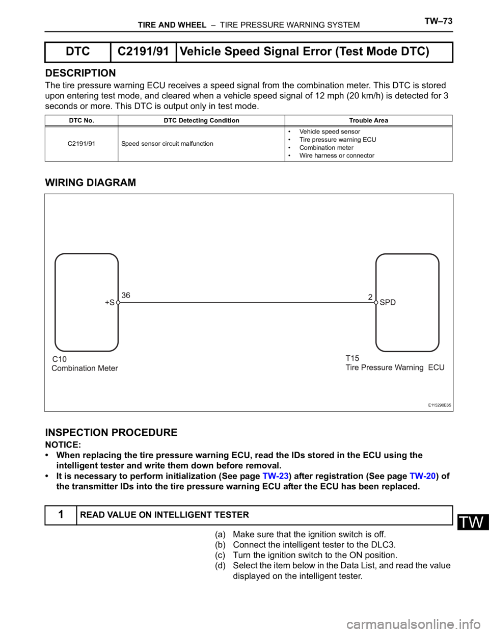
DESCRIPTION
The tire pressure warning ECU receives a speed signal from the combination meter. This DTC is stored
upon entering test mode, and cleared when a vehicle speed signal of 12 mph (20 km/h) is detected for 3
seconds or more. This DTC is output only in test mode.
WIRING DIAGRAM
INSPECTION PROCEDURE
NOTICE:
• When replacing the tire pressure warning ECU, read the IDs stored in the ECU using the
intelligent tester and write them down before removal.
• It is necessary to perform initialization (See page TW-23) after registration (See page TW-20) of
the transmitter IDs into the tire pressure warning ECU after the ECU has been replaced.
(a) Make sure that the ignition switch is off.
(b) Connect the intelligent tester to the DLC3.
(c) Turn the ignition switch to the ON position.
(d) Select the item below in the Data List, and read the value
displayed on the intelligent tester.
DTC C2191/91 Vehicle Speed Signal Error (Test Mode DTC)
DTC No. DTC Detecting Condition Trouble Area
C2191/91 Speed sensor circuit malfunction• Vehicle speed sensor
• Tire pressure warning ECU
• Combination meter
• Wire harness or connector
1READ VALUE ON INTELLIGENT TESTER
E115290E65
Page 2317 of 3000
TIRE AND WHEEL – TIRE PRESSURE WARNING SYSTEMTW–75
TW
DESCRIPTION
The ECU enters the initialization mode and performs initialization automatically, when the tire pressure
warning ECU receives the signal from the tire pressure warning reset switch. If the ECU receives the
signal, the tire pressure warning light blinks 3 times (1 second on, 1 second off).
WIRING DIAGRAM
INSPECTION PROCEDURE
(a) Perform the tire pressure warning reset switch test in
TEST MODE PROCEDURE (See page TW-25).
OK:
Reset switch ON:
Tire pressure warning light comes on.
Reset switch OFF:
Tire pressure warning light blinks.
NG
OK
Tire Pressure Warning Reset Switch Circuit
1CHECK TIRE PRESSURE WARNING RESET SWITCH FUNCTION
C148712E07
Go to step 2
END
Page 2340 of 3000
TW–28TIRE AND WHEEL – TIRE PRESSURE WARNING SYSTEM
TW
TEST MODE PROCEDURE
1. ENTER TEST MODE
HINT:
• Operation of the tire pressure warning reset switch
can be checked in TEST MODE.
• During TEST MODE, the system is not initialized by
pushing the tire pressure warning reset switch. The
circuit of the tire pressure warning reset switch can be
inspected during this mode.
(a) Make sure that the ignition switch is off.
(b) Connect the intelligent tester to DLC3.
(c) Turn the ignition switch to the ON position.
(d) Check that the tire pressure warning light comes on
for 3 seconds and then goes off.
(e) Select the TEST MODE on the intelligent tester.
(f) Confirm that the tire pressure warning light in the
combination meter blinks at 0.125-second intervals.
2. PERFORM SIGNAL CHECK
HINT:
• When entering signal check mode, the tire pressure
warning ECU sets all the signal check DTCs first.
After completing signal check for each inspection
item, the DTCs for systems that are determined to be
normal by the tire pressure warning ECU will be
erased.
The DTCs for other inspection items may not be
erased when only a certain signal is inspected.
• When signal check returns to normal mode, all the
signal check DTCs will be erased.
(a) Make sure that the ignition switch is off.
(b) Connect the intelligent tester to DLC3.
(c) Turn the ignition switch to the ON position.
C122887
F100632E04
Page 2341 of 3000
TIRE AND WHEEL – TIRE PRESSURE WARNING SYSTEMTW–29
TW
(d) Select the SIGNAL CHECK on the intelligent tester.
HINT:
Every time the test mode DTC clear conditions are
satisfied, the tire pressure warning light comes on
for 1 second. Then, the tire pressure warning light
blinks at 0.125-second intervals.
(e) Drive the vehicle at 12 mph (20 km/h) or more for 10
seconds or more to check the vehicle speed signal
(C2191/91).
(f) Loosen the valve core and rapidly reduce the
pressure (at least 40 kPa (0.41 kg/cm
2, 5.8 psi)
within 30 seconds or more) to check the transmitter
data (C2181/81 to C2184/84).
HINT:
The transmitter ID can be transmitted by rapidly
reducing the tire pressure.
(g) Check that the tire pressure warning system test
mode DTCs are erased.
(h) Check the tire pressure warning reset switch.
(1) Press the tire pressure warning reset switch.
C110644
Test Mode DTC Test Signal Test Mode DTC Clear Condition
C2181/81 to C2184/84 Transmitter DataData is received from the transmitter which has a registered ID in
the tire pressure warning ECU
C2191/91 Vehicle Speed SignalVehicle speed of 12 mph (20 km/h) or more is detected for 3
seconds or more
Page 2353 of 3000
TIRE AND WHEEL – TIRE PRESSURE WARNING SYSTEMTW–35
TW
3. DIAGNOSIS SYSTEM
(a) DTCs (Normal mode)
(1) DTCs are memorized in the tire pressure
warning ECU and read by the blinks of the tire
pressure warning light or by using the intelligent
tester (See page TW-34).
(b) Test mode
(1) By switching from normal mode into test mode
(input signal check), you can inspect the tire
pressure warning antenna and receiver, each
tire pressure warning valve and transmitter, and
vehicle speed sensor (See page TW-25).
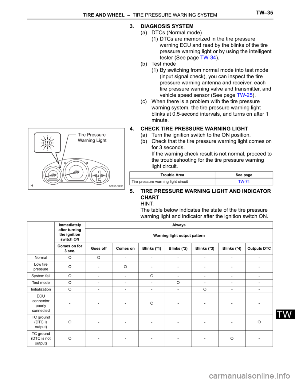
(c) When there is a problem with the tire pressure
warning system, the tire pressure warning light
blinks at 0.5-second intervals, and turns on after 1
minute.
4. CHECK TIRE PRESSURE WARNING LIGHT
(a) Turn the ignition switch to the ON position.
(b) Check that the tire pressure warning light comes on
for 3 seconds.
If the warning check result is not normal, proceed to
the troubleshooting for the tire pressure warning
light circuit.
5. TIRE PRESSURE WARNING LIGHT AND INDICATOR
CHART
HINT:
The table below indicates the state of the tire pressure
warning light and indicator after the ignition switch ON.
C159176E01
Trouble Area See page
Tire pressure warning light circuitTW-74
Immediately
after turning
the ignition
switch ONAlways
Warning light output pattern
Comes on for
3 sec.Goes off Comes on Blinks (*1) Blinks (*2) Blinks (*3) Blinks (*4) Outputs DTC
Normal
--- - - -
Low tire
pressure
--- - - -
System fail
---- - -
Te s t m o d e
------
Initialization
- -----
ECU
connector
poorly
connected---
-- - -
TC ground
(DTC is
output)
- --- - -
TC ground
(DTC is not
output)- --- --