2007 TOYOTA SIENNA ECO mode
[x] Cancel search: ECO modePage 2368 of 3000
BC–4BRAKE CONTROL – ANTI-LOCK BRAKE SYSTEM
BC
TEST MODE PROCEDURE
1. SPEED SENSOR SIGNAL CHECK (WHEN USING SST
CHECK WIRE):
HINT:
• If the ignition switch is turned from the ON to the ACC
or LOCK position during Test Mode, the DTCs of the
signal check function will be erased.
(a) Turn the ignition switch off.
(b) Check that the steering wheel is in the straight-
ahead position and move the shift lever to the P
position (Automatic Transmission) or apply the
parking brake (Manual Transmission).
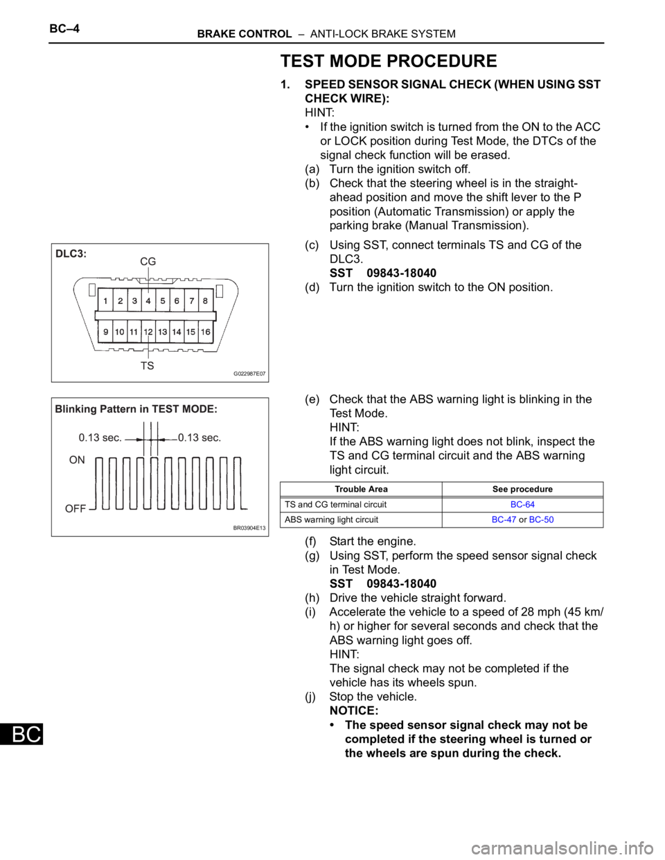
(c) Using SST, connect terminals TS and CG of the
DLC3.
SST 09843-18040
(d) Turn the ignition switch to the ON position.
(e) Check that the ABS warning light is blinking in the
Test Mode.
HINT:
If the ABS warning light does not blink, inspect the
TS and CG terminal circuit and the ABS warning
light circuit.
(f) Start the engine.
(g) Using SST, perform the speed sensor signal check
in Test Mode.
SST 09843-18040
(h) Drive the vehicle straight forward.
(i) Accelerate the vehicle to a speed of 28 mph (45 km/
h) or higher for several seconds and check that the
ABS warning light goes off.
HINT:
The signal check may not be completed if the
vehicle has its wheels spun.
(j) Stop the vehicle.
NOTICE:
• The speed sensor signal check may not be
completed if the steering wheel is turned or
the wheels are spun during the check.
G022987E07
BR03904E13
Trouble Area See procedure
TS and CG terminal circuitBC-64
ABS warning light circuitBC-47 or BC-50
Page 2369 of 3000
BRAKE CONTROL – ANTI-LOCK BRAKE SYSTEMBC–5
BC
• After the ABS warning light goes off and if
vehicle speed exceeds 50 mph (80 km/h), the
signal check code will be stored again.
Decelerate or stop the vehicle before the
speed reaches 50 mph (80 km/h).
• If the signal check has not been completed,
the ABS warning light blinks while driving
and the ABS system does not operate.
HINT:
When the signal check has been completed, the
ABS warning light goes off while driving and blinks
in the Test Mode pattern while stationary.
2. READ DTC
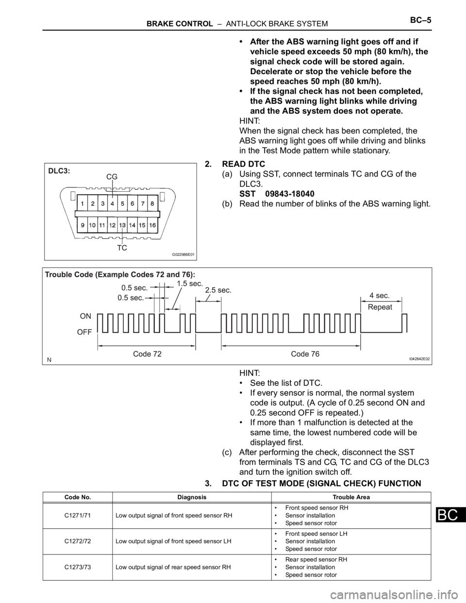
(a) Using SST, connect terminals TC and CG of the
DLC3.
SST 09843-18040
(b) Read the number of blinks of the ABS warning light.
HINT:
• See the list of DTC.
• If every sensor is normal, the normal system
code is output. (A cycle of 0.25 second ON and
0.25 second OFF is repeated.)
• If more than 1 malfunction is detected at the
same time, the lowest numbered code will be
displayed first.
(c) After performing the check, disconnect the SST
from terminals TS and CG, TC and CG of the DLC3
and turn the ignition switch off.
3. DTC OF TEST MODE (SIGNAL CHECK) FUNCTION
G022986E01
I042842E02
Code No. Diagnosis Trouble Area
C1271/71 Low output signal of front speed sensor RH• Front speed sensor RH
• Sensor installation
• Speed sensor rotor
C1272/72 Low output signal of front speed sensor LH• Front speed sensor LH
• Sensor installation
• Speed sensor rotor
C1273/73 Low output signal of rear speed sensor RH• Rear speed sensor RH
• Sensor installation
• Speed sensor rotor
Page 2370 of 3000
BC–6BRAKE CONTROL – ANTI-LOCK BRAKE SYSTEM
BC
HINT:
The codes in this table are output only in Test Mode
(signal check).
4. SPEED SENSOR SIGNAL CHECK (WHEN USING
INTELLIGENT TESTER):
HINT:
• If the ignition switch is turned from the ON to the ACC
or LOCK position during Test Mode, DTCs of the
signal check function will be erased.
• During Test Mode, the ECU records all DTCs of the
signal check function. By performing the signal check,
the codes are erased if normality is confirmed. The
remaining codes are the codes where an abnormality
was found.
(a) Turn the ignition switch off.
(b) Check that the steering wheel is in the straight-
ahead position.
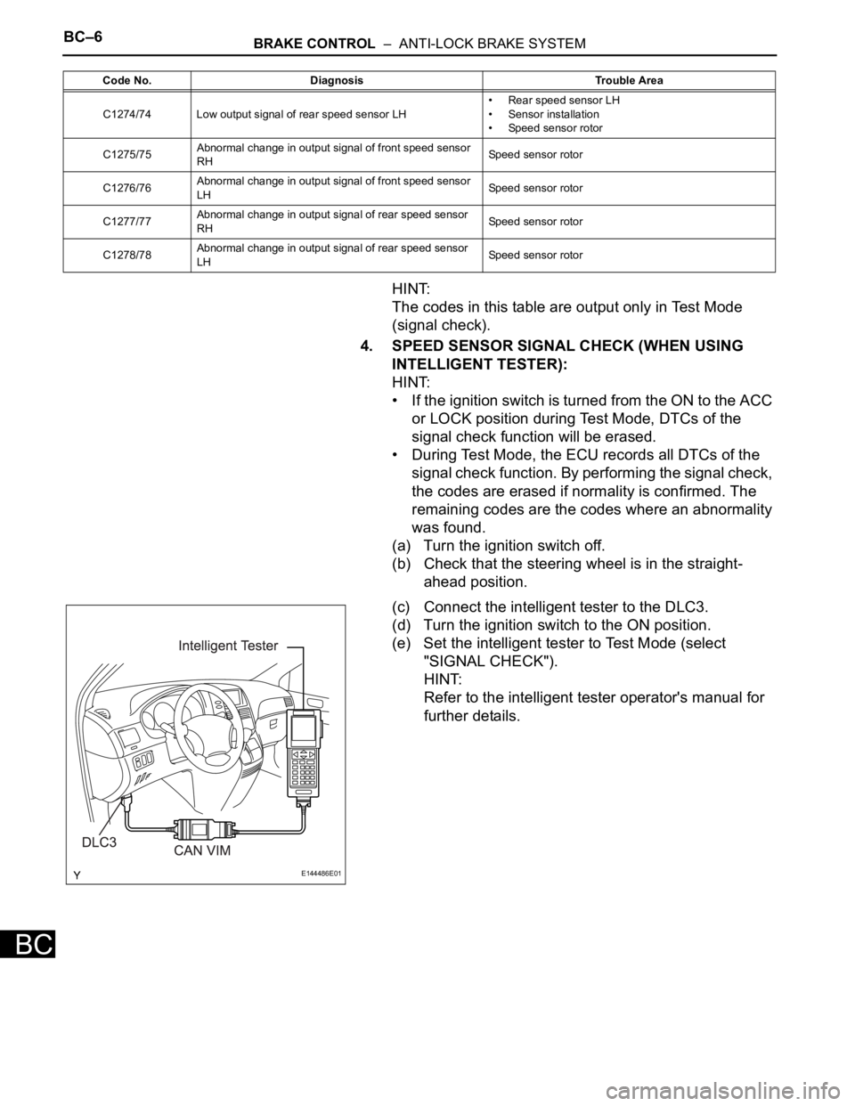
(c) Connect the intelligent tester to the DLC3.
(d) Turn the ignition switch to the ON position.
(e) Set the intelligent tester to Test Mode (select
"SIGNAL CHECK").
HINT:
Refer to the intelligent tester operator's manual for
further details.
C1274/74 Low output signal of rear speed sensor LH• Rear speed sensor LH
• Sensor installation
• Speed sensor rotor
C1275/75Abnormal change in output signal of front speed sensor
RHSpeed sensor rotor
C1276/76Abnormal change in output signal of front speed sensor
LHSpeed sensor rotor
C1277/77Abnormal change in output signal of rear speed sensor
RHSpeed sensor rotor
C1278/78Abnormal change in output signal of rear speed sensor
LHSpeed sensor rotor Code No. Diagnosis Trouble Area
E144486E01
Page 2371 of 3000
BRAKE CONTROL – ANTI-LOCK BRAKE SYSTEMBC–7
BC
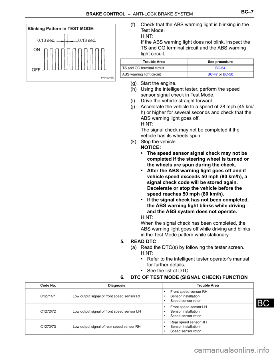
(f) Check that the ABS warning light is blinking in the
Test Mode.
HINT:
If the ABS warning light does not blink, inspect the
TS and CG terminal circuit and the ABS warning
light circuit.
(g) Start the engine.
(h) Using the intelligent tester, perform the speed
sensor signal check in Test Mode.
(i) Drive the vehicle straight forward.
(j) Accelerate the vehicle to a speed of 28 mph (45 km/
h) or higher for several seconds and check that the
ABS warning light goes off.
HINT:
The signal check may not be completed if the
vehicle has its wheels spun.
(k) Stop the vehicle.
NOTICE:
• The speed sensor signal check may not be
completed if the steering wheel is turned or
the wheels are spun during the check.
• After the ABS warning light goes off and if
vehicle speed exceeds 50 mph (80 km/h), a
signal check code will be stored again.
Decelerate or stop the vehicle before the
speed reaches 50 mph (80 km/h).
• If the signal check has not been completed,
the ABS warning light blinks while driving
and the ABS system does not operate.
HINT:
When the signal check has been completed, the
ABS warning light goes off while driving and blinks
in the Test Mode pattern while stationary.
5. READ DTC
(a) Read the DTC(s) by following the tester screen.
HINT:
• Refer to the intelligent tester operator's manual
for further details.
• See the list of DTC.
6. DTC OF TEST MODE (SIGNAL CHECK) FUNCTION
BR03904E13
Trouble Area See procedure
TS and CG terminal circuitBC-64
ABS warning light circuitBC-47 or BC-50
Code No. Diagnosis Trouble Area
C1271/71 Low output signal of front speed sensor RH• Front speed sensor RH
• Sensor installation
• Speed sensor rotor
C1272/72 Low output signal of front speed sensor LH• Front speed sensor LH
• Sensor installation
• Speed sensor rotor
C1273/73 Low output signal of rear speed sensor RH• Rear speed sensor RH
• Sensor installation
• Speed sensor rotor
Page 2373 of 3000

BRAKE CONTROL – ANTI-LOCK BRAKE SYSTEMBC–25
BC
DESCRIPTION
Refer to DTCs C0200/31, C0205/32, C1235/35, and C1236/36 (See page BC-17).
DTCs C1273/73 to C1278/78 can be deleted when the speed sensor sends a vehicle speed signal or the
Test Mode ends. DTCs C1273/73 to C1278/78 are output only in the Test Mode.
HINT:
• DTC C0210/33 and C1238/38 are for the rear speed sensor RH.
• DTC C0215/34 and C1239/39 are for the rear speed sensor LH.
DTC C0210/33 Rear Speed Sensor RH Circuit
DTC C0215/34 Rear Speed Sensor LH Circuit
DTC C1238/38Foreign Object is Attached on Tip of Rear
Speed Sensor RH
DTC C1239/39Foreign Object is Attached on Tip of Rear
Speed Sensor LH
DTC C1273/73Low Output Signal of Rear Speed Sensor RH
(Test Mode DTC)
DTC C1274/74Low Output Signal of Rear Speed Sensor LH
(Test Mode DTC)
DTC C1277/77Abnormal Change in Output Signal of Rear
Speed Sensor RH (Test Mode DTC)
DTC C1278/78Abnormal Change in Output Signal of Rear
Speed Sensor LH (Test Mode DTC)
DTC No. DTC Detection Condition Trouble Area
C0210/33
C0215/34With vehicle speed at 10 km/h (6 mph) or more, sensor
signal circuit of faulty wheel is open or short for 1
second or more.
• Momentary interruption of sensor signal of faulty
wheel has occurred 7 times or more.
• Sensor signal circuit is open for 0.5 seconds or
more.• Rear speed sensor RH/LH
• Rear speed sensor RH/LH circuit
• Speed sensor rotor
• Sensor installation
• Brake actuator assembly
C1238/38
C1239/39At vehicle speed of 20 km/h (12 mph) or more, condition
that noise is included in speed sensor signal continues
for 5 seconds or more.• Rear speed sensor RH/LH
• Speed sensor rotor
• Sensor installation
• Brake actuator assembly
Page 2387 of 3000
BC–20BRAKE CONTROL – ANTI-LOCK BRAKE SYSTEM
BC
HINT:
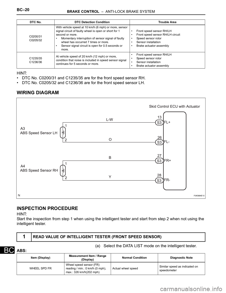
• DTC No. C0200/31 and C1235/35 are for the front speed sensor RH.
• DTC No. C0205/32 and C1236/36 are for the front speed sensor LH.
WIRING DIAGRAM
INSPECTION PROCEDURE
HINT:
Start the inspection from step 1 when using the intelligent tester and start from step 2 when not using the
intelligent tester.
(a) Select the DATA LIST mode on the intelligent tester.
ABS:
DTC No. DTC Detection Condition Trouble Area
C0200/31
C0205/32With vehicle speed at 10 km/h (6 mph) or more, sensor
signal circuit of faulty wheel is open or short for 1
second or more.
• Momentary interruption of sensor signal of faulty
wheel has occurred 7 times or more.
• Sensor signal circuit is open for 0.5 seconds or
more.• Front speed sensor RH/LH
• Front speed sensor RH/LH circuit
• Speed sensor rotor
• Sensor installation
• Brake actuator assembly
C1235/35
C1236/36At vehicle speed of 20 km/h (12 mph) or more,
condition that noise is included in speed sensor signal
continues for 5 seconds or more.• Front speed sensor RH/LH
• Speed sensor rotor
• Sensor installation
• Brake actuator assembly
1READ VALUE OF INTELLIGENT TESTER (FRONT SPEED SENSOR)
F040884E10
Item (Display)Measurement Item / Range
(Display)Normal Condition Diagnostic Note
WHEEL SPD FRWheel speed sensor (FR)
reading / min.: 0 km/h (0 mph),
max.: 326 km/h(202 mph)Actual wheel speedSimilar speed as indicated on
speedometer
Page 2395 of 3000
BC–34BRAKE CONTROL – ANTI-LOCK BRAKE SYSTEM
BC
NG
OK
(a) Install the ABS 1 fuse.
(b) Disconnect the skid control ECU connector.
(c) Measure the voltage according to the value(s) in the
table below.
Standard voltage
NG
OK
(a) Measure the resistance according to the value(s) in the
table below.
Standard resistance
NG
OK
(a) Reconnect the skid control ECU connector.
(b) Connect the intelligent tester to the DLC3.
(c) Turn the ignition switch to the ON position and turn the
intelligent tester main switch on.
(d) Start the engine.
(e) Select the ACTIVE TEST mode on the intelligent tester.
ABS:REPLACE FUSE (ABS 1 FUSE)
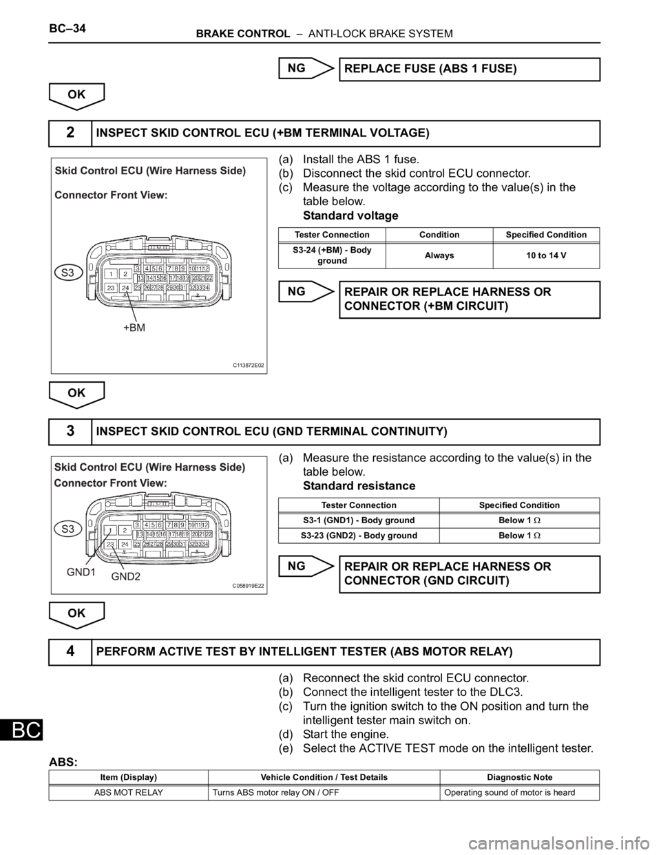
2INSPECT SKID CONTROL ECU (+BM TERMINAL VOLTAGE)
C113872E02
Tester Connection Condition Specified Condition
S3-24 (+BM) - Body
groundAlways 10 to 14 V
REPAIR OR REPLACE HARNESS OR
CONNECTOR (+BM CIRCUIT)
3INSPECT SKID CONTROL ECU (GND TERMINAL CONTINUITY)
C058919E22
Tester Connection Specified Condition
S3-1 (GND1) - Body ground Below 1
S3-23 (GND2) - Body ground Below 1
REPAIR OR REPLACE HARNESS OR
CONNECTOR (GND CIRCUIT)
4PERFORM ACTIVE TEST BY INTELLIGENT TESTER (ABS MOTOR RELAY)
Item (Display) Vehicle Condition / Test Details Diagnostic Note
ABS MOT RELAY Turns ABS motor relay ON / OFF Operating sound of motor is heard
Page 2408 of 3000
BRAKE CONTROL – ANTI-LOCK BRAKE SYSTEMBC–47
BC
DESCRIPTION
The motor relay (semiconductor relay) is housed in the brake actuator assembly and drives the pump
motor based on a signal from the skid control ECU.
WIRING DIAGRAM
Refer to DTCs C0273/13 and C0274/14 (See page BC-31).
INSPECTION PROCEDURE
HINT:
After step 1 is complete, start the inspection from step 2 when using the intelligent tester, and from step 3
when not using the intelligent tester.
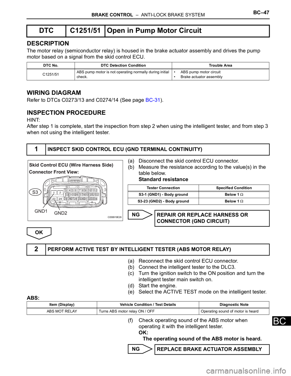
(a) Disconnect the skid control ECU connector.
(b) Measure the resistance according to the value(s) in the
table below.
Standard resistance
NG
OK
(a) Reconnect the skid control ECU connector.
(b) Connect the intelligent tester to the DLC3.
(c) Turn the ignition switch to the ON position and turn the
intelligent tester main switch on.
(d) Start the engine.
(e) Select the ACTIVE TEST mode on the intelligent tester.
ABS:
(f) Check operating sound of the ABS motor when
operating it with the intelligent tester.
OK:
The operating sound of the ABS motor is heard.
NG
DTC C1251/51 Open in Pump Motor Circuit
DTC No. DTC Detection Condition Trouble Area
C1251/51ABS pump motor is not operating normally during initial
check.• ABS pump motor circuit
• Brake actuator assembly
1INSPECT SKID CONTROL ECU (GND TERMINAL CONTINUITY)
C058919E26
Tester Connection Specified Condition
S3-1 (GND1) - Body ground Below 1
S3-23 (GND2) - Body ground Below 1
REPAIR OR REPLACE HARNESS OR
CONNECTOR (GND CIRCUIT)
2PERFORM ACTIVE TEST BY INTELLIGENT TESTER (ABS MOTOR RELAY)
Item (Display) Vehicle Condition / Test Details Diagnostic Note
ABS MOT RELAY Turns ABS motor relay ON / OFF Operating sound of motor is heard
REPLACE BRAKE ACTUATOR ASSEMBLY