2007 TOYOTA SIENNA ECO mode
[x] Cancel search: ECO modePage 50 of 3000

IN–38INTRODUCTION – HOW TO TROUBLESHOOT ECU CONTROLLED SYSTEMS
IN
HINT:
• In troubleshooting, confirm that the problem symptoms
have been accurately identified. Preconceptions should be
discarded in order to make an accurate judgment. To
clearly understand what the problem symptoms are, it is
extremely important to ask the customer about the
problem and the conditions at the time the malfunction
occurred.
• Gather as much information as possible for reference.
Past problems that seem unrelated may also help in some
cases.
• The following 5 items are important points in the problem
analysis:
3. SYMPTOM CONFIRMATION AND DIAGNOSTIC
TROUBLE CODE
HINT:
The diagnostic system in the SIENNA has various
functions.
• The first function is the Diagnostic Trouble Code
(DTC) check. A DTC is a code stored in the ECU
memory whenever a malfunction in the signal circuits
to the ECU occurs. In a DTC check, a previous
malfunction's DTC can be checked by a technician
during troubleshooting.
• Another function is the Input Signal Check, which
checks if the signals from various switches are sent to
the ECU correctly.
By using these functions, the problem areas can be
narrowed down and troubleshooting is more effective.
Diagnostic functions are incorporated in the following
system in the SIENNA.
What Vehicle model, system name
When Date, time, occurrence frequency
Where Road conditions
Under what conditions? Running conditions, driving conditions, weather conditions
How did it happen? Problem symptoms
SystemSYMPTOM CONFIRMATION AND DIAGNOSTIC TROUBLE CODE
DTC Check
(Normal Mode)DTC Check
(Check Mode)Sensor Check/
Test Mode
(Input Signal
Check)Data List Active Test
2GR-FE SFI System
X
U151E Automatic Transaxle SystemX
U151F Automatic Transaxle SystemX
Tire pressure warning systemXX
Anti-lock Brake System
X
Vehicle Stability Control SystemX
Air Conditioning System (for Manual Air
Conditioning System)XXXXX
Air Conditioning System (for Automatic Air
Conditioning System)
XX
Airbag SystemXX
Occupant Classification System
XXX
Page 57 of 3000

IN–50INTRODUCTION – TERMS
IN
GLOSSARY OF SAE AND TOYOTA
TERMS
This glossary lists all SAE-J1930 terms and abbreviations
used in this manual in compliance with SAE
recommendations, as well as their TOYOTA equivalents.
SAE
ABBREVIATIONSSAE TERMSTOYOTA TERMS
( )-ABBREVIATIONS
A/C Air Conditioning Air Conditioner
ACL Air Cleaner Air Cleaner, A/CL
AIR Secondary Air Injection Air Injection (AI)
AP Accelerator Pedal -
B+ Battery Positive Voltage +B, Battery Voltage
BARO Barometric Pressure HAC
CAC Charge Air Cooler Intercooler
CARB Carburetor Carburetor
CFI Continuous Fuel Injection -
CKP Crankshaft Position Crank Angle
CL Closed Loop Closed Loop
CMP Camshaft Position Cam Angle
CPP Clutch Pedal Position -
CTOX Continuous Trap Oxidizer -
CTP Closed Throttle Position LL ON, Idle ON
DFI Direct Fuel Injection Direct Injection (DI./INJ)
DI Distributor Ignition -
DLC3 Data Link Connector 3 OBD II Diagnostic Connector
DTC Diagnostic Trouble Code Diagnostic Trouble Code
DTM Diagnostic Test Mode -
ECL Engine Coolant Level -
ECM Engine Control Module Engine Electronic Control Unit (ECU)
ECT Engine Coolant Temperature Coolant Temperature, Water Temperature (THW)
EEPROM Electrically Erasable Programmable Read Only MemoryElectrically Erasable Programmable Read Only
Memory (EEPROM), Erasable Programmable Read
Only Memory (EPROM)
EFE Early Fuel Evaporation Cold Mixture Heater (CMH), Heat Control Valve (HCV)
EGR Exhaust Gas Recirculation Exhaust Gas Recirculation (EGR)
EI Electronic Ignition Distributorless Ignition (DLI)
EM Engine Modification Engine Modification (EM)
EPROM Erasable Programmable Read Only Memory Programmable Read Only Memory (PROM)
EVAP Evaporative Emission Evaporative Emission Control (EVAP)
FC Fan Control -
FEEPROMFlash Electrically Erasable Programmable Read Only
Memory-
FEPROM Flash Erasable Programmable Read Only Memory -
FF Flexible Fuel -
FP Fuel Pump Fuel Pump
GEN Generator Alternator
GND Ground Ground (GND)
HO2S Heated Oxygen SensorHeated Oxygen Sensor (HO
2S)
IAC Idle Air Control Idle Speed Control (ISC)
IAT Intake Air Temperature Intake or Inlet Air Temperature
ICM Ignition Control Module -
Page 68 of 3000

IN–38INTRODUCTION – HOW TO TROUBLESHOOT ECU CONTROLLED SYSTEMS
IN
HINT:
• In troubleshooting, confirm that the problem symptoms
have been accurately identified. Preconceptions should be
discarded in order to make an accurate judgment. To
clearly understand what the problem symptoms are, it is
extremely important to ask the customer about the
problem and the conditions at the time the malfunction
occurred.
• Gather as much information as possible for reference.
Past problems that seem unrelated may also help in some
cases.
• The following 5 items are important points in the problem
analysis:
3. SYMPTOM CONFIRMATION AND DIAGNOSTIC
TROUBLE CODE
HINT:
The diagnostic system in the SIENNA has various
functions.
• The first function is the Diagnostic Trouble Code
(DTC) check. A DTC is a code stored in the ECU
memory whenever a malfunction in the signal circuits
to the ECU occurs. In a DTC check, a previous
malfunction's DTC can be checked by a technician
during troubleshooting.
• Another function is the Input Signal Check, which
checks if the signals from various switches are sent to
the ECU correctly.
By using these functions, the problem areas can be
narrowed down and troubleshooting is more effective.
Diagnostic functions are incorporated in the following
system in the SIENNA.
What Vehicle model, system name
When Date, time, occurrence frequency
Where Road conditions
Under what conditions? Running conditions, driving conditions, weather conditions
How did it happen? Problem symptoms
SystemSYMPTOM CONFIRMATION AND DIAGNOSTIC TROUBLE CODE
DTC Check
(Normal Mode)DTC Check
(Check Mode)Sensor Check/
Test Mode
(Input Signal
Check)Data List Active Test
2GR-FE SFI System
X
U151E Automatic Transaxle SystemX
U151F Automatic Transaxle SystemX
Tire pressure warning systemXX
Anti-lock Brake System
X
Vehicle Stability Control SystemX
Air Conditioning System (for Manual Air
Conditioning System)XXXXX
Air Conditioning System (for Automatic Air
Conditioning System)
XX
Airbag SystemXX
Occupant Classification System
XXX
Page 180 of 3000

BC–4BRAKE CONTROL – ANTI-LOCK BRAKE SYSTEM
BC
TEST MODE PROCEDURE
1. SPEED SENSOR SIGNAL CHECK (WHEN USING SST
CHECK WIRE):
HINT:
• If the ignition switch is turned from the ON to the ACC
or LOCK position during Test Mode, the DTCs of the
signal check function will be erased.
(a) Turn the ignition switch off.
(b) Check that the steering wheel is in the straight-
ahead position and move the shift lever to the P
position (Automatic Transmission) or apply the
parking brake (Manual Transmission).
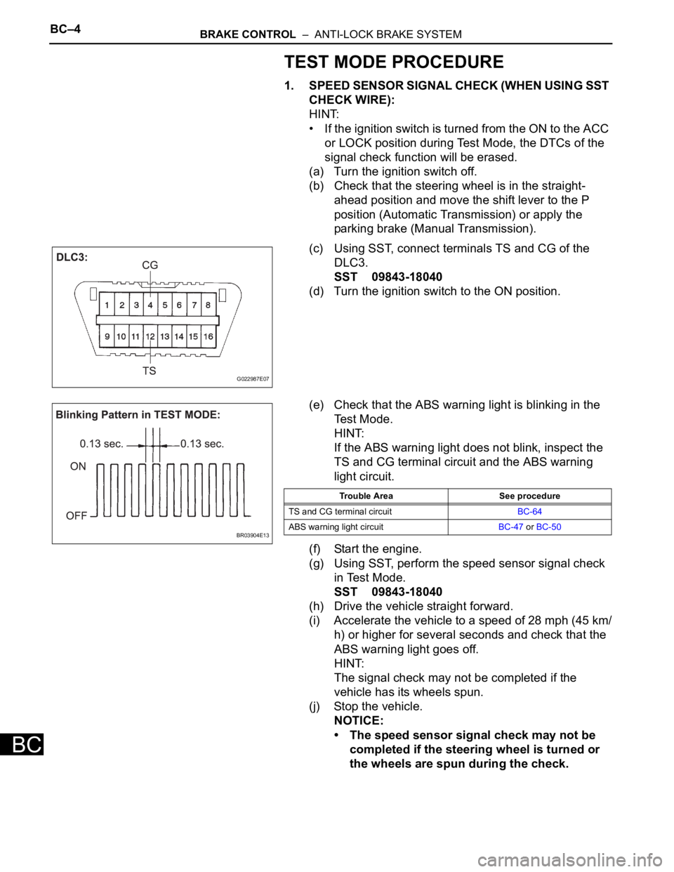
(c) Using SST, connect terminals TS and CG of the
DLC3.
SST 09843-18040
(d) Turn the ignition switch to the ON position.
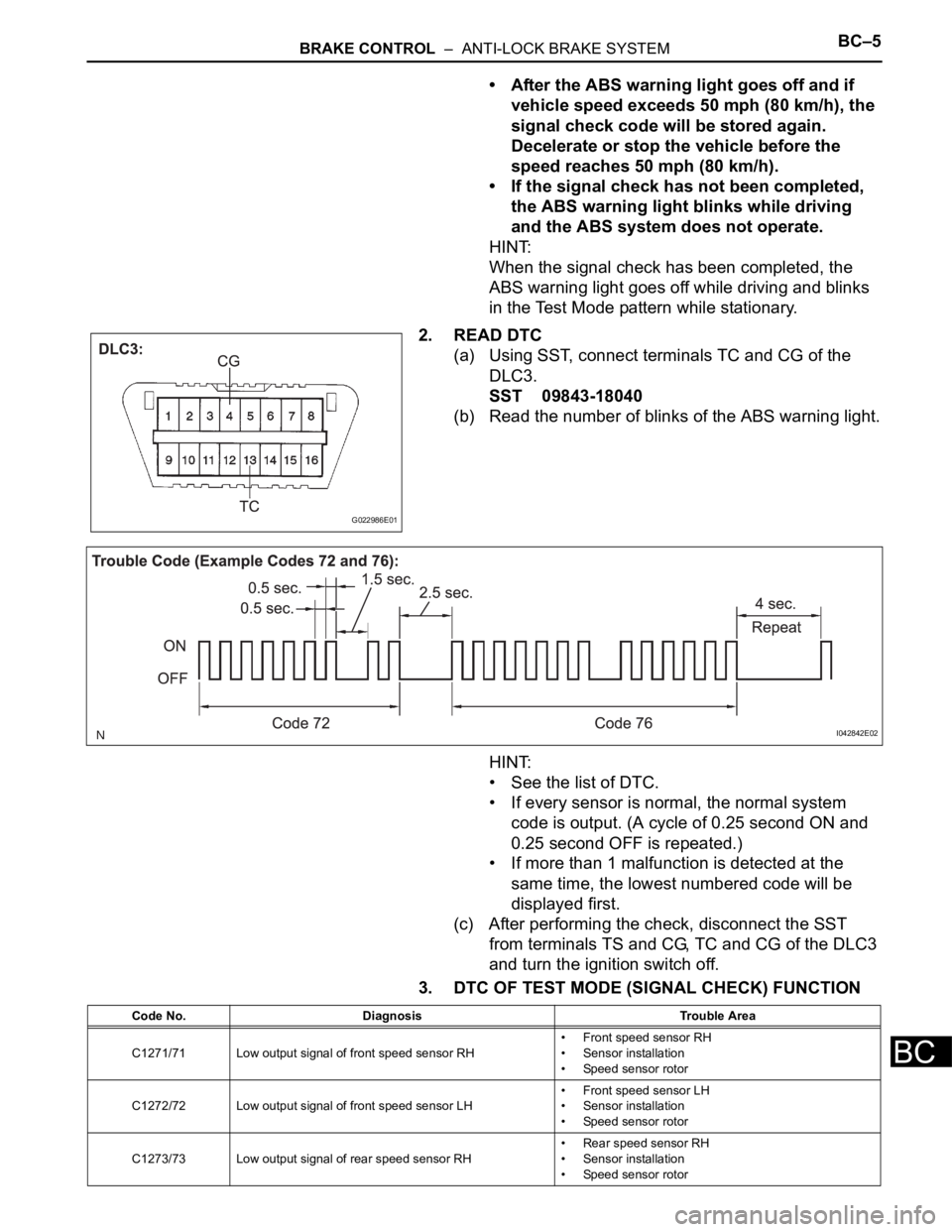
(e) Check that the ABS warning light is blinking in the
Test Mode.
HINT:
If the ABS warning light does not blink, inspect the
TS and CG terminal circuit and the ABS warning
light circuit.
(f) Start the engine.
(g) Using SST, perform the speed sensor signal check
in Test Mode.
SST 09843-18040
(h) Drive the vehicle straight forward.
(i) Accelerate the vehicle to a speed of 28 mph (45 km/
h) or higher for several seconds and check that the
ABS warning light goes off.
HINT:
The signal check may not be completed if the
vehicle has its wheels spun.
(j) Stop the vehicle.
NOTICE:
• The speed sensor signal check may not be
completed if the steering wheel is turned or
the wheels are spun during the check.
G022987E07
BR03904E13
Trouble Area See procedure
TS and CG terminal circuitBC-64
ABS warning light circuitBC-47 or BC-50
Page 181 of 3000

BRAKE CONTROL – ANTI-LOCK BRAKE SYSTEMBC–5
BC
• After the ABS warning light goes off and if
vehicle speed exceeds 50 mph (80 km/h), the
signal check code will be stored again.
Decelerate or stop the vehicle before the
speed reaches 50 mph (80 km/h).
• If the signal check has not been completed,
the ABS warning light blinks while driving
and the ABS system does not operate.
HINT:
When the signal check has been completed, the
ABS warning light goes off while driving and blinks
in the Test Mode pattern while stationary.
2. READ DTC
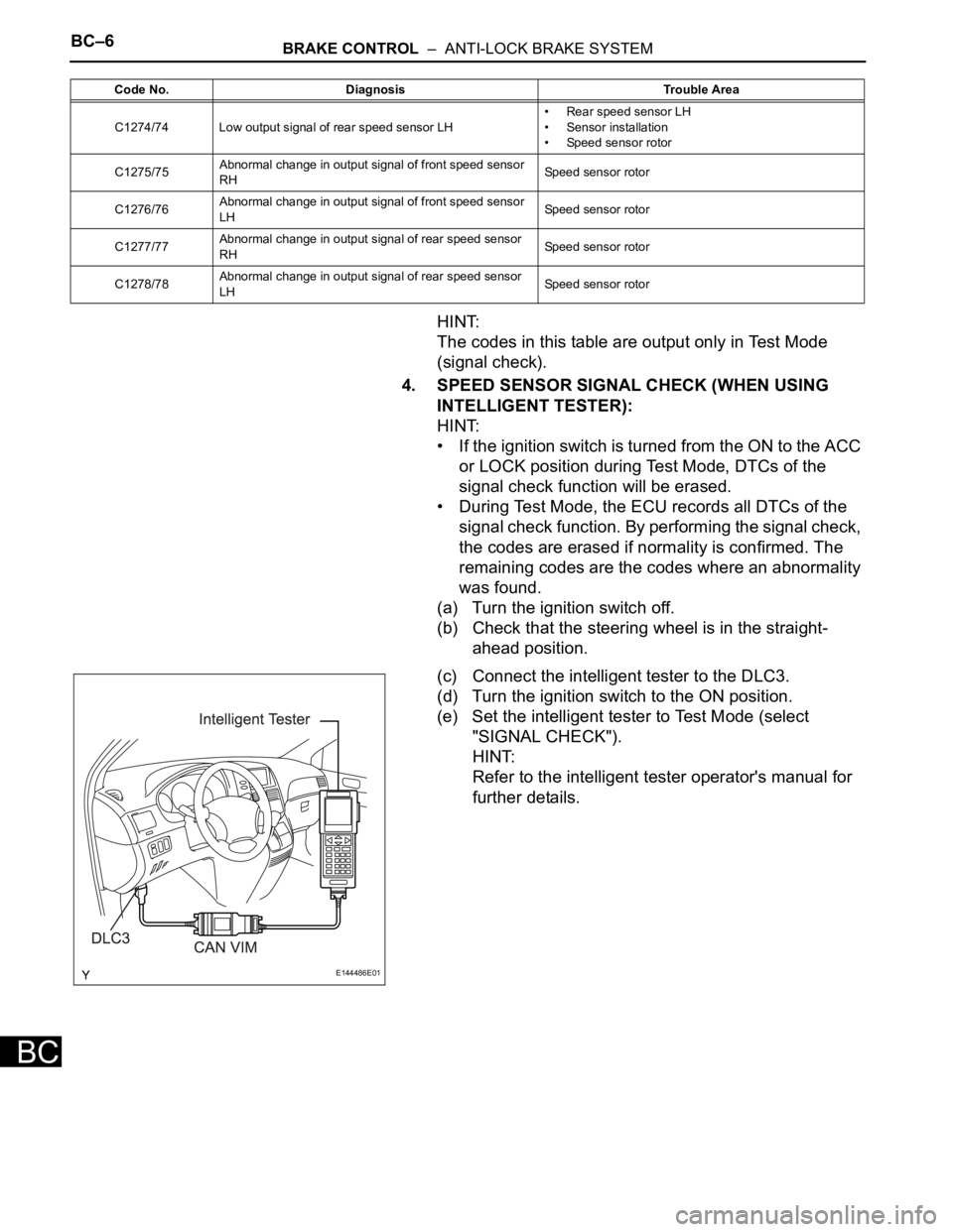
(a) Using SST, connect terminals TC and CG of the
DLC3.
SST 09843-18040
(b) Read the number of blinks of the ABS warning light.
HINT:
• See the list of DTC.
• If every sensor is normal, the normal system
code is output. (A cycle of 0.25 second ON and
0.25 second OFF is repeated.)
• If more than 1 malfunction is detected at the
same time, the lowest numbered code will be
displayed first.
(c) After performing the check, disconnect the SST
from terminals TS and CG, TC and CG of the DLC3
and turn the ignition switch off.
3. DTC OF TEST MODE (SIGNAL CHECK) FUNCTION
G022986E01
I042842E02
Code No. Diagnosis Trouble Area
C1271/71 Low output signal of front speed sensor RH• Front speed sensor RH
• Sensor installation
• Speed sensor rotor
C1272/72 Low output signal of front speed sensor LH• Front speed sensor LH
• Sensor installation
• Speed sensor rotor
C1273/73 Low output signal of rear speed sensor RH• Rear speed sensor RH
• Sensor installation
• Speed sensor rotor
Page 182 of 3000

BC–6BRAKE CONTROL – ANTI-LOCK BRAKE SYSTEM
BC
HINT:
The codes in this table are output only in Test Mode
(signal check).
4. SPEED SENSOR SIGNAL CHECK (WHEN USING
INTELLIGENT TESTER):
HINT:
• If the ignition switch is turned from the ON to the ACC
or LOCK position during Test Mode, DTCs of the
signal check function will be erased.
• During Test Mode, the ECU records all DTCs of the
signal check function. By performing the signal check,
the codes are erased if normality is confirmed. The
remaining codes are the codes where an abnormality
was found.
(a) Turn the ignition switch off.
(b) Check that the steering wheel is in the straight-
ahead position.
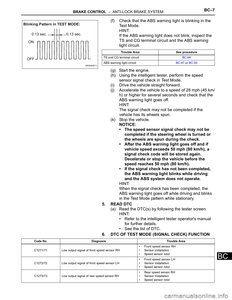
(c) Connect the intelligent tester to the DLC3.
(d) Turn the ignition switch to the ON position.
(e) Set the intelligent tester to Test Mode (select
"SIGNAL CHECK").
HINT:
Refer to the intelligent tester operator's manual for
further details.
C1274/74 Low output signal of rear speed sensor LH• Rear speed sensor LH
• Sensor installation
• Speed sensor rotor
C1275/75Abnormal change in output signal of front speed sensor
RHSpeed sensor rotor
C1276/76Abnormal change in output signal of front speed sensor
LHSpeed sensor rotor
C1277/77Abnormal change in output signal of rear speed sensor
RHSpeed sensor rotor
C1278/78Abnormal change in output signal of rear speed sensor
LHSpeed sensor rotor Code No. Diagnosis Trouble Area
E144486E01
Page 183 of 3000

BRAKE CONTROL – ANTI-LOCK BRAKE SYSTEMBC–7
BC
(f) Check that the ABS warning light is blinking in the
Test Mode.
HINT:
If the ABS warning light does not blink, inspect the
TS and CG terminal circuit and the ABS warning
light circuit.
(g) Start the engine.
(h) Using the intelligent tester, perform the speed
sensor signal check in Test Mode.
(i) Drive the vehicle straight forward.
(j) Accelerate the vehicle to a speed of 28 mph (45 km/
h) or higher for several seconds and check that the
ABS warning light goes off.
HINT:
The signal check may not be completed if the
vehicle has its wheels spun.
(k) Stop the vehicle.
NOTICE:
• The speed sensor signal check may not be
completed if the steering wheel is turned or
the wheels are spun during the check.
• After the ABS warning light goes off and if
vehicle speed exceeds 50 mph (80 km/h), a
signal check code will be stored again.
Decelerate or stop the vehicle before the
speed reaches 50 mph (80 km/h).
• If the signal check has not been completed,
the ABS warning light blinks while driving
and the ABS system does not operate.
HINT:
When the signal check has been completed, the
ABS warning light goes off while driving and blinks
in the Test Mode pattern while stationary.
5. READ DTC
(a) Read the DTC(s) by following the tester screen.
HINT:
• Refer to the intelligent tester operator's manual
for further details.
• See the list of DTC.
6. DTC OF TEST MODE (SIGNAL CHECK) FUNCTION
BR03904E13
Trouble Area See procedure
TS and CG terminal circuitBC-64
ABS warning light circuitBC-47 or BC-50
Code No. Diagnosis Trouble Area
C1271/71 Low output signal of front speed sensor RH• Front speed sensor RH
• Sensor installation
• Speed sensor rotor
C1272/72 Low output signal of front speed sensor LH• Front speed sensor LH
• Sensor installation
• Speed sensor rotor
C1273/73 Low output signal of rear speed sensor RH• Rear speed sensor RH
• Sensor installation
• Speed sensor rotor
Page 236 of 3000

THEFT DETERRENT – THEFT DETERRENT SYSTEMTD–3
TD
SYSTEM DESCRIPTION
1. OUTLINE OF THEFT DETERRENT SYSTEM
(a) When the theft deterrent system detects that the
vehicle is being tampered with, the system sets off
the alarm, causing the horns to sound and the lights
to light up or blink in order to alert people around the
vehicle to the theft.
(b) The theft deterrent system has 2 modes; one is the
active arming mode (see ACTIVE ARMING MODE)
and the other is passive arming mode (see
PASSIVE ARMING MODE). The passive arming
mode can be switched ON/OFF using the specified
method.
(c) Each mode has 4 states; a disarmed state, an
arming preparation state, an armed state and an
alarm sounding state.
(1) Disarmed state:
• The alarm function is not operating.
• The theft deterrent system is not operating.
(2) Arming preparation state:
• The time until the system goes into the armed
state.
• The theft deterrent system is not operating.
(3) Armed state:
• The theft deterrent system is operating.
(4) Alarm sounding state:
• Alarm function is operating.
Alarm time:
Approx. 60 sec.
Refer to table below for alarm method and time:
HINT:
If any of the doors are unlocked with no key in
the ignition key cylinder during the armed state,
a forced door lock signal will be output (see
FORCED DOOR LOCK CONTROL).
2. ACTIVE ARMING MODE
HINT:
• Active arming mode starts the alarm control
immediately after the doors are locked.
• This system activates as described in the diagram
below when one of items for each condition is met.
Alarm MethodHeadlight Blinking (approx. 0.4 second cycles)
Taillight Blinking (approx. 0.4 second cycles)
Hazard Warning Light Blinking (cycles of flasher relay)
Interior Light Illuminating
Vehicle HornSounding
(approx. 0.4 second cycles)
Security HornSounding
(approx. 0.4 second cycles)
Alarm Time Approx. 60 sec.