2007 TOYOTA SIENNA ECO mode
[x] Cancel search: ECO modePage 629 of 3000

ES–3362GR-FE ENGINE CONTROL SYSTEM – SFI SYSTEM
ES
DESCRIPTION
The park/neutral position switch detects the shift lever position and sends signals to the ECM.
HINT:
After confirming DTC P0705, use the intelligent tester to confirm the PNP switch signal in the ALL menu
(to reach the ALL menu: DIAGNOSIS / ENHANCED OBD II / DATA LIST / ALL).
WIRING DIAGRAM
Refer to DTC P0705 for 2WD model (See page AX-40) or 4WD model (See page AX-40).
INSPECTION PROCEDURE
Refer to DTC P0705 for 2WD model (See page AX-41) or 4WD model (See page AX-41).
HINT:
Read freeze frame data using the intelligent tester or OBD II scan tool. The ECM records vehicle and
driving condition information as freeze frame data the moment a DTC is stored. When troubleshooting,
freeze frame data can help determine if the vehicle was running or stopped, if the engine was warmed up
or not, if the air-fuel ratio was LEAN or RICH, and other data from the time the malfunction occurred.
DTC P0705Transmission Range Sensor Circuit Malfunc-
tion (PRNDL Input)
DTC No. DTC Detection Condition Trouble Area
P0705(A) Any 2 or more signals of the following are ON
simultaneously (2-trip detection logic)
• P input signal is ON.
• N input signal is ON.
• R input signal is ON.
• D input signal is ON.
(B) Any 2 ore more signals of the following are ON
simultaneously (2-trip detection logic)
• NSW input signal is ON.
• R input signal is ON.
• D input signal is ON.
(C) Any of following conditions is met for 2.0 sec. or more in
the S position (2-trip detection logic).
• NSW input signal is ON.
• P input signal is ON.
• N input signal is ON.
• R input signal is ON.
(D) All switches are OFF simultaneously for NSW, P, R, N and
D.• Open or short in park/neutral position switch circuit
• Park/neutral position switch
•ECM
Page 635 of 3000

ES–3422GR-FE ENGINE CONTROL SYSTEM – SFI SYSTEM
ES
*: System guard set when following conditions met
TYPICAL MALFUNCTION THRESHOLDS
P2111 (Throttle actuator stuck open):
P2112 (Throttle actuator stuck closed):
FA I L - S A F E
When either of these DTCs, as well as other DTCs relating to ETCS (Electronic Throttle Control System)
malfunctions, is set, the ECM enters fail-safe mode. During fail-safe mode, the ECM cuts the current to
the throttle actuator off, and the throttle valve is returned to a 6
throttle angle by the return spring. The
ECM then adjusts the engine output by controlling the fuel injection (intermittent fuel-cut) and ignition
timing, in accordance with the accelerator pedal opening angle, to allow the vehicle to continue at a
minimal speed.
If the accelerator pedal is depressed slowly, the vehicle can be driven slowly.
Fail-safe mode continues until a pass condition is detected, and the ignition switch is then turned off.
WIRING DIAGRAM
Refer to DTC P2102 (See page ES-331).
INSPECTION PROCEDURE
HINT:
Read freeze frame data using the intelligent tester. The ECM records vehicle and driving condition
information as freeze frame data the moment a DTC is stored. When troubleshooting, freeze frame data
can be helpful in determining whether the vehicle was running or stopped, whether the engine was
warmed up or not, whether the air-fuel ratio was lean or rich, as well as other data recorded at the time of
a malfunction.
(a) Connect the intelligent tester to the DLC3.
(b) Turn the ignition switch to the ON position.
(c) Turn the tester on.
(d) Select the following menu items: DIAGNOSIS /
ENHANCED OBD II / DTC INFO / CURRENT CODES.
(e) Read the DTCs.
Result
Throttle actuator open duty-cycle 80% or more
Throttle actuator ON
Throttle actuator duty calculation Executing
Throttle position sensor Fail determined
Throttle actuator current-cut operation Not executing
Throttle actuator power supply 4 V or more
Throttle actuator Fail determined
TP sensor voltage change No change
TP sensor voltage change No change
1CHECK ANY OTHER DTCS OUTPUT (IN ADDITION TO DTC P2111 OR P2112)
Display (DTC Output) Proceed to
P2111 or P2112 A
P2111 or P2112 and other DTCs B
Page 642 of 3000

2GR-FE ENGINE CONTROL SYSTEM – SFI SYSTEMES–349
ES
FAIL-SAFE
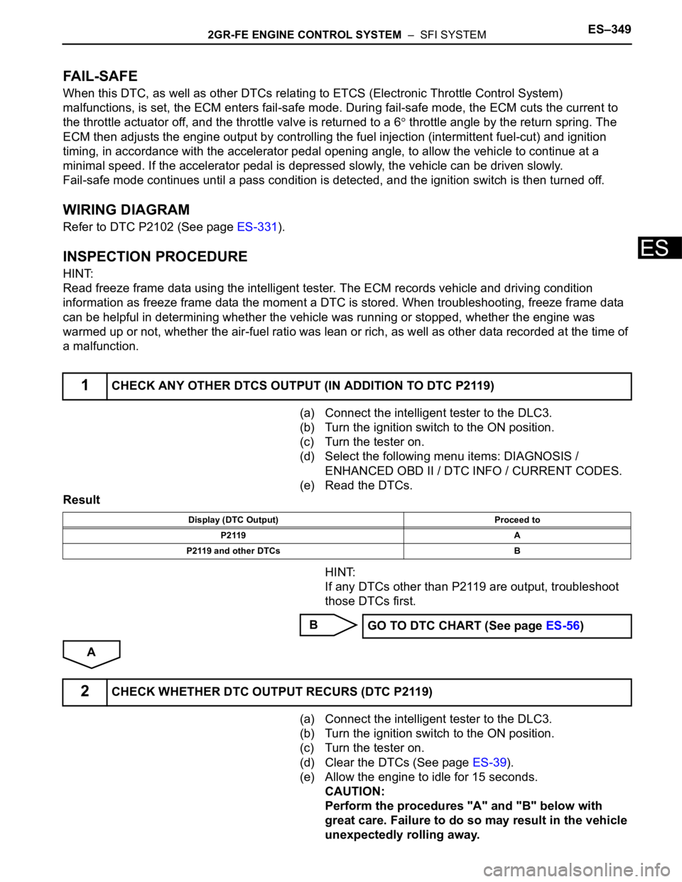
When this DTC, as well as other DTCs relating to ETCS (Electronic Throttle Control System)
malfunctions, is set, the ECM enters fail-safe mode. During fail-safe mode, the ECM cuts the current to
the throttle actuator off, and the throttle valve is returned to a 6
throttle angle by the return spring. The
ECM then adjusts the engine output by controlling the fuel injection (intermittent fuel-cut) and ignition
timing, in accordance with the accelerator pedal opening angle, to allow the vehicle to continue at a
minimal speed. If the accelerator pedal is depressed slowly, the vehicle can be driven slowly.
Fail-safe mode continues until a pass condition is detected, and the ignition switch is then turned off.
WIRING DIAGRAM
Refer to DTC P2102 (See page ES-331).
INSPECTION PROCEDURE
HINT:
Read freeze frame data using the intelligent tester. The ECM records vehicle and driving condition
information as freeze frame data the moment a DTC is stored. When troubleshooting, freeze frame data
can be helpful in determining whether the vehicle was running or stopped, whether the engine was
warmed up or not, whether the air-fuel ratio was lean or rich, as well as other data recorded at the time of
a malfunction.
(a) Connect the intelligent tester to the DLC3.
(b) Turn the ignition switch to the ON position.
(c) Turn the tester on.
(d) Select the following menu items: DIAGNOSIS /
ENHANCED OBD II / DTC INFO / CURRENT CODES.
(e) Read the DTCs.
Result
HINT:
If any DTCs other than P2119 are output, troubleshoot
those DTCs first.
B
A
(a) Connect the intelligent tester to the DLC3.
(b) Turn the ignition switch to the ON position.
(c) Turn the tester on.
(d) Clear the DTCs (See page ES-39).
(e) Allow the engine to idle for 15 seconds.
CAUTION:
Perform the procedures "A" and "B" below with
great care. Failure to do so may result in the vehicle
unexpectedly rolling away.
1CHECK ANY OTHER DTCS OUTPUT (IN ADDITION TO DTC P2119)
Display (DTC Output) Proceed to
P2119 A
P2119 and other DTCs B
GO TO DTC CHART (See page ES-56)
2CHECK WHETHER DTC OUTPUT RECURS (DTC P2119)
Page 652 of 3000

2GR-FE ENGINE CONTROL SYSTEM – SFI SYSTEMES–359
ES
HINT:
This DTC relates to the Accelerator Pedal Position (APP) sensor.
DESCRIPTION
Refer to DTC P2120 (See page ES-343).
MONITOR DESCRIPTION
The accelerator pedal position sensor is mounted on the accelerator pedal bracket. The accelerator pedal
position sensor has 2 sensor elements and 2 signal outputs: VPA and VPA2. VPA is used to detect the
actual accelerator pedal angle (used for engine control) and VPA2 is used to detect malfunctions in VPA.
When the difference between the voltage outputs of VPA and VPA2 deviates from the standard, the ECM
determines that the accelerator pedal position sensor is malfunctioning. The ECM turns on the MIL and
the DTC is set.
MONITOR STRATEGY
TYPICAL ENABLING CONDITIONS
TYPICAL MALFUNCTION THRESHOLDS
FAIL-SAFE
The accelerator pedal position sensor has 2 (main and sub) sensor circuits. If a malfunction occurs in
either of the sensor circuits, the ECM detects the abnormal signal voltage difference between the 2 sensor
circuits and switches to limp mode. In limp mode, the functioning circuit is used to calculate the
accelerator pedal opening angle to allow the vehicle to continue driving. If both circuits malfunction, the
ECM regards the opening angle of the accelerator pedal as being fully closed. In this case, the throttle
valve remains closed as if the engine is idling.
DTC P2121Throttle / Pedal Position Sensor / Switch "D"
Circuit Range / Performance
DTC No. DTC Detection Condition Trouble Area
P2121Difference between VPA and VPA2 is less than 0.4 V, or
more than 1.2 V for 0.5 seconds (1 trip detection logic)• Accelerator position (APP) sensor
•ECM
Related DTCs P2121: Accelerator pedal position (APP) sensor rationality
Required Sensors / Components (Main) APP sensor
Required Sensors / Components (Related) -
Frequency of Operation Continuous
Duration 0.5 seconds
MIL Operation Immediate
Sequence of Operation None
The monitor will run whenever these DTCs are not
presentNone
Either of the following conditions is met. Condition 1 or 2
1. Ignition switch ON
2. Electronic throttle actuator power ON
Difference between VPA1 voltage (learned value) and
VPA2 voltage (learned value)Less than 0.4 V, or more than 1.2 V
Page 668 of 3000

2GR-FE ENGINE CONTROL SYSTEM – SFI SYSTEMES–375
ES
B
A
(a) Has the vehicle run out of fuel in the past?.
NO
YES
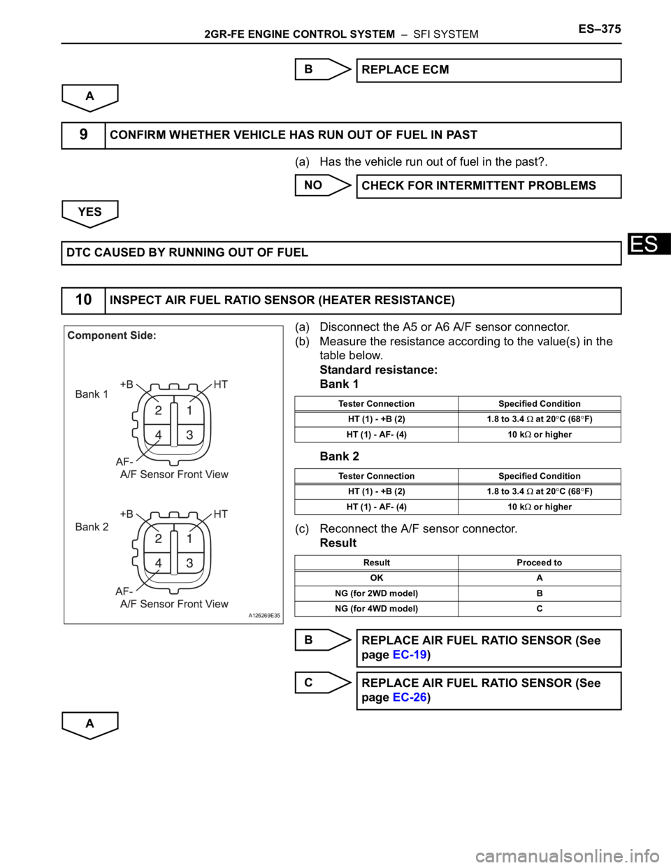
(a) Disconnect the A5 or A6 A/F sensor connector.
(b) Measure the resistance according to the value(s) in the
table below.
Standard resistance:
Bank 1
Bank 2
(c) Reconnect the A/F sensor connector.
Result
B
C
AREPLACE ECM
9CONFIRM WHETHER VEHICLE HAS RUN OUT OF FUEL IN PAST
CHECK FOR INTERMITTENT PROBLEMS
DTC CAUSED BY RUNNING OUT OF FUEL
10INSPECT AIR FUEL RATIO SENSOR (HEATER RESISTANCE)
A126269E35
Tester Connection Specified Condition
HT (1) - +B (2) 1.8 to 3.4
at 20C (68F)
HT (1) - AF- (4) 10 k
or higher
Tester Connection Specified Condition
HT (1) - +B (2) 1.8 to 3.4
at 20C (68F)
HT (1) - AF- (4) 10 k
or higher
Result Proceed to
OK A
NG (for 2WD model) B
NG (for 4WD model) C
REPLACE AIR FUEL RATIO SENSOR (See
page EC-19)
REPLACE AIR FUEL RATIO SENSOR (See
page EC-26)
Page 677 of 3000

ES–3842GR-FE ENGINE CONTROL SYSTEM – SFI SYSTEM
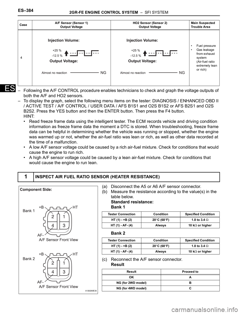
ES– Following the A/F CONTROL procedure enables technicians to check and graph the voltage outputs of
both the A/F and HO2 sensors.
– To display the graph, select the following menu items on the tester: DIAGNOSIS / ENHANCED OBD II
/ ACTIVE TEST / A/F CONTROL / USER DATA / AFS B1S1 and O2S B1S2 or AFS B2S1 and O2S
B2S2. Press the YES button and then the ENTER button. Then press the F4 button.
HINT:
• Read freeze frame data using the intelligent tester. The ECM records vehicle and driving condition
information as freeze frame data the moment a DTC is stored. When troubleshooting, freeze frame
data can be helpful in determining whether the vehicle was running or stopped, whether the engine
was warmed up or not, whether the air-fuel ratio was lean or rich, as well as other data recorded at
the time of a malfunction.
• A low A/F sensor voltage could be caused by a rich air-fuel mixture. Check for conditions that would
cause the engine to run rich.
• A high A/F sensor voltage could be caused by a lean air-fuel mixture. Check for conditions that
would cause the engine to run lean.
(a) Disconnect the A5 or A6 A/F sensor connector.
(b) Measure the resistance according to the value(s) in the
table below.
Standard resistance:
Bank 1
Bank 2
(c) Reconnect the A/F sensor connector.
Result
4•Fuel pressure
• Gas leakage
from exhaust
system
(Air-fuel ratio
extremely lean
or rich)
1INSPECT AIR FUEL RATIO SENSOR (HEATER RESISTANCE)
CaseA/F Sensor (Sensor 1)
Output VoltageHO2 Sensor (Sensor 2)
Output VoltageMain Suspected
Trouble Area
A126269E35
Tester Connection Condition Specified Condition
HT (1) - +B (2) 20
C (68F) 1.8 to 3.4
HT (1) - AF- (4) Always 10 k or higher
Tester Connection Condition Specified Condition
HT (1) - +B (2) 20
C (68F) 1.8 to 3.4
HT (1) - AF- (4) Always 10 k or higher
Result Proceed to
OK A
NG (for 2WD model) B
NG (for 4WD model) C
Page 694 of 3000

2GR-FE ENGINE CONTROL SYSTEM – SFI SYSTEMES–401
ES
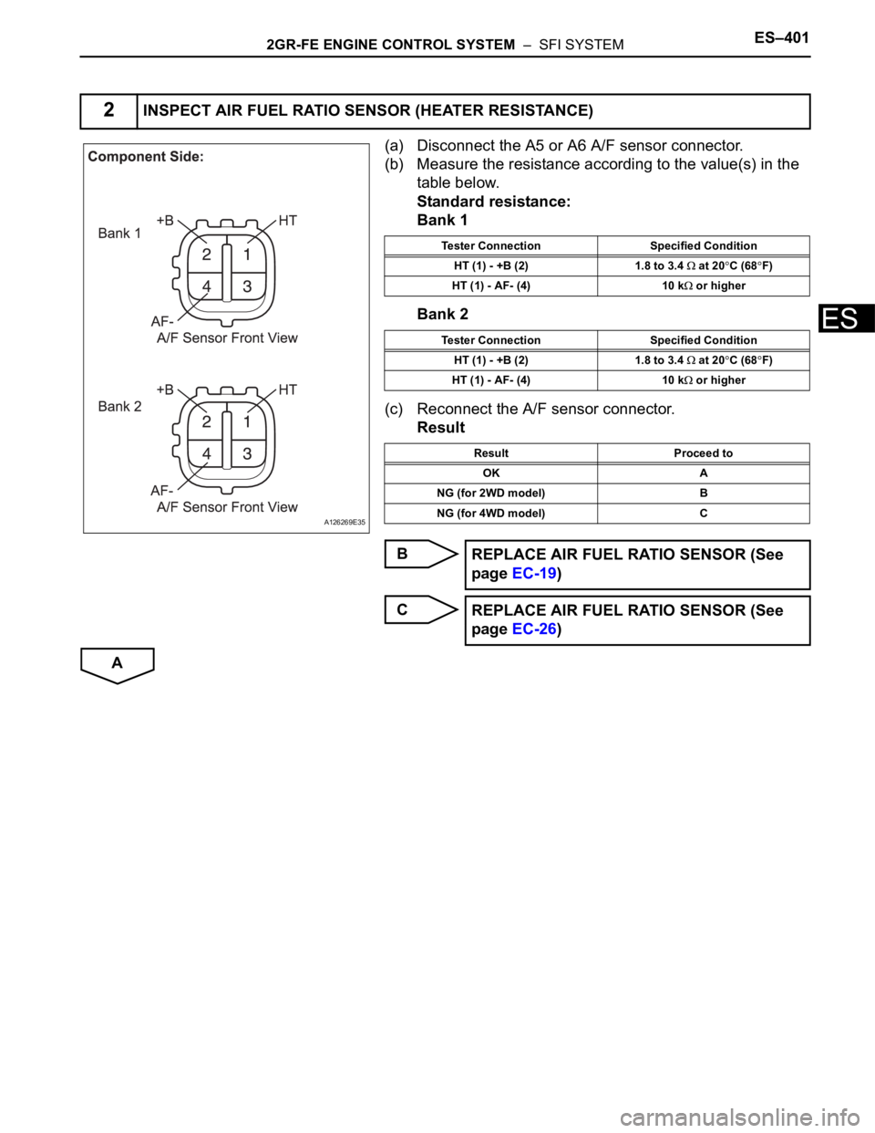
(a) Disconnect the A5 or A6 A/F sensor connector.
(b) Measure the resistance according to the value(s) in the
table below.
Standard resistance:
Bank 1
Bank 2
(c) Reconnect the A/F sensor connector.
Result
B
C
A
2INSPECT AIR FUEL RATIO SENSOR (HEATER RESISTANCE)
A126269E35
Tester Connection Specified Condition
HT (1) - +B (2) 1.8 to 3.4
at 20C (68F)
HT (1) - AF- (4) 10 k
or higher
Tester Connection Specified Condition
HT (1) - +B (2) 1.8 to 3.4
at 20C (68F)
HT (1) - AF- (4) 10 k
or higher
Result Proceed to
OK A
NG (for 2WD model) B
NG (for 4WD model) C
REPLACE AIR FUEL RATIO SENSOR (See
page EC-19)
REPLACE AIR FUEL RATIO SENSOR (See
page EC-26)
Page 824 of 3000

ES–422GR-FE ENGINE CONTROL SYSTEM – SFI SYSTEM
ES
In order to enhance OBD function on vehicles and
develop the Off-Board diagnosis system, CAN
communication is introduced in this system (CAN:
Controller Area Network). It minimizes a gap
between technician skills and vehicle technology.
CAN is a network, which uses a pair of data
transmission lines, spanning multiple computers
and sensors. It allows a high speed communication
between the systems and to simplify the wire
harness connection.
Since this system is equipped with the CAN
communication, connecting the CAN VIM (VIM:
Vehicle Interface Module) with an intelligent tester is
necessary to display any information from the ECM.
(Also the communication between the intelligent
tester and the ECM uses CAN communication
signal.) When confirming the DTCs and any data of
the ECM, connect the CAN VIM between the DLC3
and the intelligent tester.
2. NORMAL MODE AND CHECK MODE
(a) The diagnosis system operates in normal mode
during normal vehicle use. In normal mode, 2 trip
detection logic is used to ensure accurate detection
of malfunctions. Check mode is also available as an
option for technicians. In check mode, 1 trip
detection logic is used for simulating malfunction
symptoms and increasing the system's ability to
detect malfunctions, including intermittent problems
(intelligent tester only) (See page ES-43).
3. 2 TRIP DETECTION LOGIC
(a) When a malfunction is first detected, the
malfunction is temporarily stored in the ECM
memory (1st trip). If the same malfunction is
detected during the next subsequent drive cycle, the
MIL is illuminated (2nd trip).
4. FREEZE FRAME DATA
(a) The ECM records vehicle and driving condition
information as freeze frame data the moment a DTC
is stored. When troubleshooting, freeze frame data
can be helpful in determining whether the vehicle
was running or stopped, whether the engine was
warmed up or not, whether the air-fuel ratio was
lean or rich, as well as other data recorded at the
time of a malfunction.
A082779E02