2007 TOYOTA SIENNA ECO mode
[x] Cancel search: ECO modePage 827 of 3000
2GR-FE ENGINE CONTROL SYSTEM – SFI SYSTEMES–45
ES
DTC CHECK / CLEAR
NOTICE:
All the stored DTCs and freeze frame data are erased if:
1) the ECM is changed from normal mode to check mode
or vice versa; or 2) the ignition switch is turned from ON
to ACC or off while in check mode.
Before changing modes, always check and make a note
of any DTCs and freeze frame data.
HINT:
• DTCs which are stored in the ECM can be displayed on an
intelligent tester. An intelligent tester can display current
and pending DTCs.
• Some DTCs are not set if the ECM does not detect the
same malfunction again during the second consecutive
driving cycle. However, such malfunctions, detected on
only one occasion, are stored as pending DTCs.
1. CHECK DTC (Using an intelligent tester)
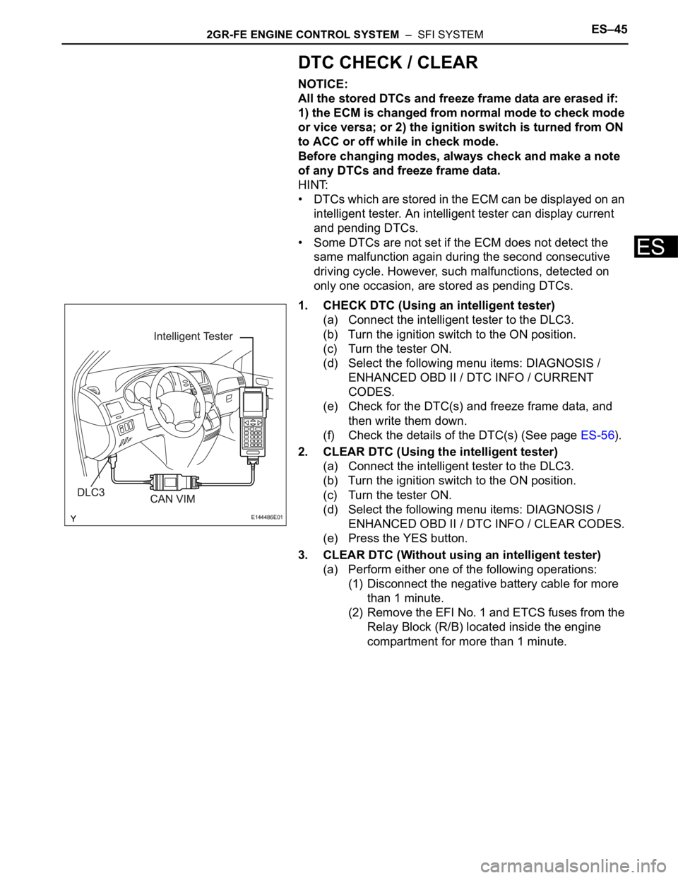
(a) Connect the intelligent tester to the DLC3.
(b) Turn the ignition switch to the ON position.
(c) Turn the tester ON.
(d) Select the following menu items: DIAGNOSIS /
ENHANCED OBD II / DTC INFO / CURRENT
CODES.
(e) Check for the DTC(s) and freeze frame data, and
then write them down.
(f) Check the details of the DTC(s) (See page ES-56).
2. CLEAR DTC (Using the intelligent tester)
(a) Connect the intelligent tester to the DLC3.
(b) Turn the ignition switch to the ON position.
(c) Turn the tester ON.
(d) Select the following menu items: DIAGNOSIS /
ENHANCED OBD II / DTC INFO / CLEAR CODES.
(e) Press the YES button.
3. CLEAR DTC (Without using an intelligent tester)
(a) Perform either one of the following operations:
(1) Disconnect the negative battery cable for more
than 1 minute.
(2) Remove the EFI No. 1 and ETCS fuses from the
Relay Block (R/B) located inside the engine
compartment for more than 1 minute.
E144486E01
Page 932 of 3000
EM–22GR-FE ENGINE MECHANICAL – ENGINE
EM
(c) When not using the intelligent tester:
Check the ignition timing.
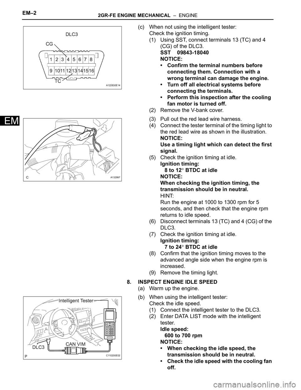
(1) Using SST, connect terminals 13 (TC) and 4
(CG) of the DLC3.
SST 09843-18040
NOTICE:
• Confirm the terminal numbers before
connecting them. Connection with a
wrong terminal can damage the engine.
• Turn off all electrical systems before
connecting the terminals.
• Perform this inspection after the cooling
fan motor is turned off.
(2) Remove the V-bank cover.
(3) Pull out the red lead wire harness.
(4) Connect the tester terminal of the timing light to
the red lead wire as shown in the illustration.
NOTICE:
Use a timing light which can detect the first
signal.
(5) Check the ignition timing at idle.
Ignition timing:
8 to 12
BTDC at idle
NOTICE:
When checking the ignition timing, the
transmission should be in neutral.
HINT:
Run the engine at 1000 to 1300 rpm for 5
seconds, and then check that the engine rpm
returns to idle speed.
(6) Disconnect terminals 13 (TC) and 4 (CG) of the
DLC3.
(7) Check the ignition timing at idle.
Ignition timing:
7 to 24
BTDC at idle
(8) Confirm that the ignition timing moves to the
advanced angle side when the engine rpm is
increased.
(9) Remove the timing light.
8. INSPECT ENGINE IDLE SPEED
(a) Warm up the engine.
(b) When using the intelligent tester:
Check the idle speed.
(1) Connect the intelligent tester to the DLC3.
(2) Enter DATA LIST mode with the intelligent
tester.
Idle speed:
600 to 700 rpm
NOTICE:
• When checking the idle speed, the
transmission should be in neutral.
• Check the idle speed with the cooling fan
off.
A122830E14
A132997
C110200E02
Page 934 of 3000

EM–42GR-FE ENGINE MECHANICAL – ENGINE
EM
(h) Install the 6 ignition coils.
Torque: 10 N*m (102 kgf*cm, 7 ft.*lbf)
(i) Install the intake air surge tank (See page ES-522).
10. INSPECT CO/HC
(a) Start the engine.
(b) Run the engine at 2500 rpm for approximately 180
seconds.
(c) Insert the CO/HC meter testing probe at least 40 cm
(1.3 ft.) into the tailpipe during idling.
(d) Check CO/HC concentration at idle and/or 2500
rpm.
HINT:
Check regulations and restrictions in your area
when performing 2 mode CO/HC concentration
testing (engine check at both idle speed and at 2500
rpm).
If the CO/HC concentration does not comply with
regulations, perform troubleshooting in the order
given below.
(1) Check air fuel ratio sensor and heated oxygen
sensor operation.
(2) See the table below for possible causes, and
then inspect and repair.
CO HC Problems Causes
Normal High Rough idle1. Faulty ignitions:
– Incorrect timing
– Fouled, shorted or improperly gapped plugs
2. Incorrect valve clearance
3. Leaks in intake and exhaust valves
4. Leaks in cylinders
Low HighRough idle
(fluctuating HC reading)1. Vacuum leaks:
– PCV hoses
– Intake manifold
– Throttle body
– Brake booster line
2. Lean mixture causing misfire
High HighRough idle
(black smoke from exhaust)1. Restricted air filter
2. Plugged PCV valve
3. Faulty SFI system:
– Faulty fuel pressure regulator
– Defective ECT sensor
– Defective MAF meter
–Faulty ECM
– Faulty injectors
– Faulty throttle position sensor
Page 1192 of 3000
EC–182GR-FE EMISSION CONTROL – AIR FUEL RATIO SENSOR (for 2WD)
EC
ON-VEHICLE INSPECTION
HINT:
The type of ignition switch on this model differs according to
the specifications of the vehicle. For the expressions used in
this section, refer to the "EXPRESSIONS OF IGNITION
SWITCH" precaution (See page ES-1).
1. CHECK AIR FUEL RATIO COMPENSATION SYSTEM
(a) Connect the intelligent tester to the DLC3.
(b) Turn the ignition switch to the ON position.
(c) Select the following menu items: Data List / A/FS B1
S1 and O2S B1 S2.
(d) Warm up the A/F sensor with the engine speed at
2500 rpm for approximately 2 minutes.
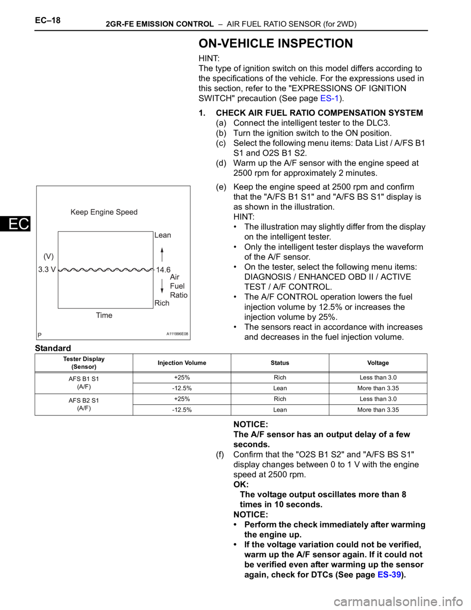
(e) Keep the engine speed at 2500 rpm and confirm
that the "A/FS B1 S1" and "A/FS BS S1" display is
as shown in the illustration.
HINT:
• The illustration may slightly differ from the display
on the intelligent tester.
• Only the intelligent tester displays the waveform
of the A/F sensor.
• On the tester, select the following menu items:
DIAGNOSIS / ENHANCED OBD II / ACTIVE
TEST / A/F CONTROL.
• The A/F CONTROL operation lowers the fuel
injection volume by 12.5% or increases the
injection volume by 25%.
• The sensors react in accordance with increases
and decreases in the fuel injection volume.
Standard
NOTICE:
The A/F sensor has an output delay of a few
seconds.
(f) Confirm that the "O2S B1 S2" and "A/FS BS S1"
display changes between 0 to 1 V with the engine
speed at 2500 rpm.
OK:
The voltage output oscillates more than 8
times in 10 seconds.
NOTICE:
• Perform the check immediately after warming
the engine up.
• If the voltage variation could not be verified,
warm up the A/F sensor again. If it could not
be verified even after warming up the sensor
again, check for DTCs (See page ES-39).
A111996E08
Tester Display
(Sensor)Injection Volume Status Voltage
AFS B1 S1
(A/F)+25% Rich Less than 3.0
-12.5% Lean More than 3.35
AFS B2 S1
(A/F)+25% Rich Less than 3.0
-12.5% Lean More than 3.35
Page 1196 of 3000
2GR-FE EMISSION CONTROL – AIR FUEL RATIO SENSOR (for 4WD)EC–25
EC
ON-VEHICLE INSPECTION
HINT:
The type of ignition switch on this model differs according to
the specifications of the vehicle. For the expressions used in
this section, refer to the "EXPRESSIONS OF IGNITION
SWITCH" precaution (See page ES-1).
1. CHECK AIR FUEL RATIO COMPENSATION SYSTEM
(a) Connect the intelligent tester to the DLC3.
(b) Turn the ignition switch to the ON position.
(c) Select the following menu items: Data List / A/FS B1
S1 and O2S B1 S2.
(d) Warm up the A/F sensor with the engine speed at
2500 rpm for approximately 2 minutes.
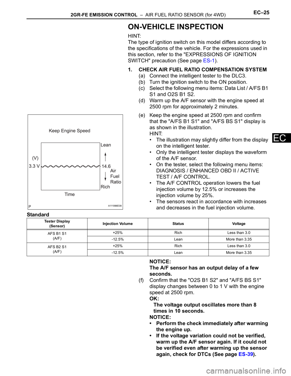
(e) Keep the engine speed at 2500 rpm and confirm
that the "A/FS B1 S1" and "A/FS BS S1" display is
as shown in the illustration.
HINT:
• The illustration may slightly differ from the display
on the intelligent tester.
• Only the intelligent tester displays the waveform
of the A/F sensor.
• On the tester, select the following menu items:
DIAGNOSIS / ENHANCED OBD II / ACTIVE
TEST / A/F CONTROL.
• The A/F CONTROL operation lowers the fuel
injection volume by 12.5% or increases the
injection volume by 25%.
• The sensors react in accordance with increases
and decreases in the fuel injection volume.
Standard
NOTICE:
The A/F sensor has an output delay of a few
seconds.
(f) Confirm that the "O2S B1 S2" and "A/FS BS S1"
display changes between 0 to 1 V with the engine
speed at 2500 rpm.
OK:
The voltage output oscillates more than 8
times in 10 seconds.
NOTICE:
• Perform the check immediately after warming
the engine up.
• If the voltage variation could not be verified,
warm up the A/F sensor again. If it could not
be verified even after warming up the sensor
again, check for DTCs (See page ES-39).
A111996E08
Tester Display
(Sensor)Injection Volume Status Voltage
AFS B1 S1
(A/F)+25% Rich Less than 3.0
-12.5% Lean More than 3.35
AFS B2 S1
(A/F)+25% Rich Less than 3.0
-12.5% Lean More than 3.35
Page 1402 of 3000
AX–32U151E AUTOMATIC TRANSAXLE – AUTOMATIC TRANSAXLE SYSTEM
AX
DTC CHECK / CLEAR
1. DTC CHECK (NORMAL MODE)
NOTICE:
When the diagnostic system is switched from the
normal mode to the check mode, all the DTCs and
freeze frame data recorded in the normal mode will
be erased. So before switching modes, always check
the DTCs and freeze frame data, and note them
down.
(a) Checking DTCs using the OBD II scan tool or
intelligent tester.
(1) Turn the ignition switch off.
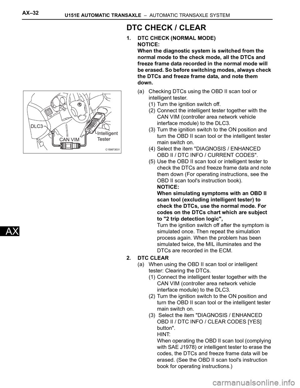
(2) Connect the intelligent tester together with the
CAN VIM (controller area network vehicle
interface module) to the DLC3.
(3) Turn the ignition switch to the ON position and
turn the OBD II scan tool or the intelligent tester
main switch on.
(4) Select the item "DIAGNOSIS / ENHANCED
OBD II / DTC INFO / CURRENT CODES".
(5) Use the OBD II scan tool or intelligent tester to
check the DTCs and freeze frame data and note
them down (For operating instructions, see the
OBD II scan tool's instruction book).
NOTICE:
When simulating symptoms with an OBD II
scan tool (excluding intelligent tester) to
check the DTCs, use the normal mode. For
codes on the DTCs chart which are subject
to "2 trip detection logic",
Turn the ignition switch off after the symptom is
simulated once. Then repeat the simulation
process again. When the problem has been
simulated twice, the MIL illuminates and the
DTCs are recorded in the ECM.
2. DTC CLEAR
(a) When using the OBD II scan tool or intelligent
tester: Clearing the DTCs.
(1) Connect the intelligent tester together with the
CAN VIM (controller area network vehicle
interface module) to the DLC3.
(2) Turn the ignition switch to the ON position and
turn the OBD II scan tool or the intelligent tester
main switch on.
(3) Select the item "DIAGNOSIS / ENHANCED
OBD II / DTC INFO / CLEAR CODES [YES]
button".
HINT:
When operating the OBD II scan tool (complying
with SAE J1978) or intelligent tester to erase the
codes, the DTCs and freeze frame data will be
erased. (See the OBD II scan tool's instruction
book for operating instructions.)
C159873E01
Page 1404 of 3000
AX–34U151E AUTOMATIC TRANSAXLE – AUTOMATIC TRANSAXLE SYSTEM
AX
CHECK MODE PROCEDURE
HINT:
Check mode has a higher sensitivity to malfunctions and can
detect malfunction that normal mode cannot detect. Check
mode can also detect all the malfunctions that normal mode
can detect. In check mode, DTCs are detected with 1-trip
detection logic.
1. DTC CHECK (CHECK MODE)
HINT:
Intelligent tester only: Compared to the normal mode, the
check mode is more sensitive for detecting malfunctions.
Furthermore, the same diagnostic items which are
detected in the normal mode can also be detected in the
check mode.
(a) Procedure for Check Mode using the intelligent
tester.
(1) Check the initial conditions.
• Battery positive voltage 11 V or more
• Throttle valve fully closed
• Transaxle in the P or N position
• A/C switch is off
(2) Turn the ignition switch off.
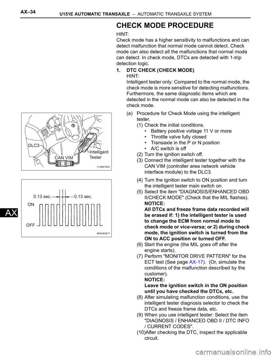
(3) Connect the intelligent tester together with the
CAN VIM (controller area network vehicle
interface module) to the DLC3.
(4) Turn the ignition switch to ON position and turn
the intelligent tester main switch on.
(5) Select the item "DIAGNOSIS/ENHANCED OBD
II/CHECK MODE" (Check that the MIL flashes).
NOTICE:
All DTCs and freeze frame data recorded will
be erased if: 1) the intelligent tester is used
to change the ECM from normal mode to
check mode or vice-versa; or 2) during check
mode, the ignition switch is turned from the
ON to ACC position or turned OFF.
(6) Start the engine (the MIL goes off after the
engine starts).
(7) Perform "MONITOR DRIVE PATTERN" for the
ECT test (See page AX-17). (Or, simulate the
conditions of the malfunction described by the
customer).
NOTICE:
Leave the ignition switch in the ON position
until you have checked the DTCs, etc.
(8) After simulating malfunction conditions, use the
intelligent tester diagnosis selector to check the
DTCs and freeze frame data, etc.
(9) When you use intelligent tester: Select the item
"DIAGNOSIS / ENHANCED OBD II / DTC INFO
/ CURRENT CODES".
(10)After checking the DTC, inspect the applicable
circuit.
C159873E01
BR03904E17
Page 1406 of 3000

AX–36U151E AUTOMATIC TRANSAXLE – AUTOMATIC TRANSAXLE SYSTEM
AX
FAIL-SAFE CHART
1. FAIL-SAFE
This function minimizes the loss of the ECT functions
when any malfunction occurs in a sensor or solenoid.
(a) ATF (Automatic Transmission Fluid) temperature
sensor:
When the ATF temperature sensor has a
malfunction, 5th upshift is prohibited.
(b) Counter gear speed sensor NC (Speed sensor NC):
When the counter gear speed sensor has a
malfunction, 5th upshift is prohibited.
(c) Shift solenoid valve DSL:
When the solenoid valve DSL has a malfunction, the
current to the solenoid valve is stopped.
This stops lock-up control, then fuel economy
decreases.
(d) Shift solenoid valve SL1, SL2, SL3 and S4:
Fail safe function:
If either of the shift solenoid valve circuits develops
an open or short, the ECM turns the other shift
solenoid "ON" and "OFF" in order to shift into the
gear positions shown in the table below.
Manual shifting as shown in the following table must
be done (In case of a short circuit, the ECM stops
sending the current to the short circuited solenoid).
Even if starting the engine in the fail-safe mode, the
gear position remains in the same position.
HINT:
FL: Flex Lock-up
NormalSolenoid ValveSL1 ON OFF ON OFF OFF
SL2 ON ON OFF FL FL
SL3 OFF OFF OFF ON ON
S4 OFF OFF OFF OFF ON
Gear Position 1st 2nd 3rd 4th 5th
SL1
Malfunction
(During driving
at 1st or 2nd)Solenoid ValveSL1 OFF
SL2 ON ON OFF to ON FL to ON FL to ON
SL3 OFF OFF OFF ON to OFF ON to OFF
S4 OFF OFF OFF OFF ON to OFF
Gear Position 1st to 2nd 2nd 3rd to 2nd 4th to 2nd 5th to 2nd
SL1
Malfunction
(During driving
at 3rd)Solenoid ValveSL1 OFF
SL2 ON to FL ON to FL OFF to FL FL FL
SL3 OFF OFF OFF ON to OFF ON to OFF
S4 OFF to ON OFF to ON OFF to ON OFF to ON ON
Gear Position 1st to 4th 2nd to 4th 3rd to 4th 4th 5th to 4th
SL1
Malfunction
(During driving
at 4th or 5th)Solenoid ValveSL1 OFF
SL2 ON to FL ON to FL OFF to FL FL FL
SL3 OFF to ON OFF to ON OFF to ON ON ON
S4 OFF OFF OFF OFF ON
Gear Position 1st to 4th 2nd to 4th 3rd to 4th 4th 5th to 4th