2007 TOYOTA SIENNA ECO mode
[x] Cancel search: ECO modePage 1542 of 3000
U151E AUTOMATIC TRANSAXLE – AUTOMATIC TRANSAXLE SYSTEMAX–29
AX
DIAGNOSIS SYSTEM
1. DESCRIPTION
(a) When troubleshooting OBD II vehicles, the only
difference from the usual troubleshooting procedure
is to connect an OBD II scan tool complying with
SAE J1987 or a intelligent tester to the vehicle, and
read off various data output from the vehicle's ECM.
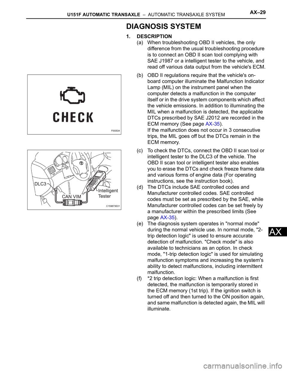
(b) OBD II regulations require that the vehicle's on-
board computer illuminate the Malfunction Indicator
Lamp (MIL) on the instrument panel when the
computer detects a malfunction in the computer
itself or in the drive system components whic h affect
the vehicle emissions. In addition to illuminating the
MIL when a malfunction is detected, the applicable
DTCs prescribed by SAE J2012 are recorded in the
ECM memory (See page AX-35).
If the malfunction does not occur in 3 consecutive
trips, the MIL goes off but the DTCs remain in the
ECM memory.
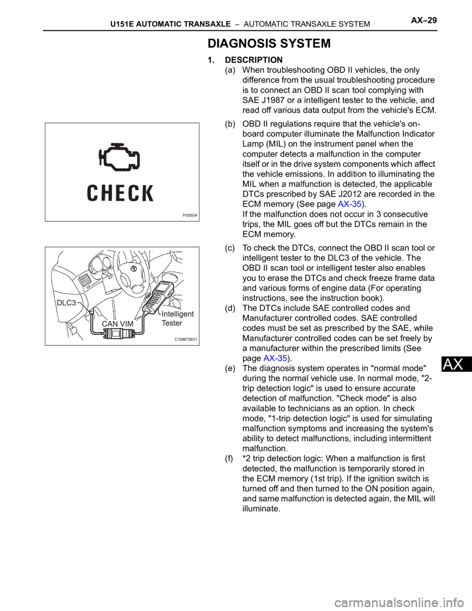
(c) To check the DTCs, connect the OBD II scan tool or
intelligent tester to the DLC3 of the vehicle. The
OBD II scan tool or intelligent tester also enables
you to erase the DTCs and check freeze frame data
and various forms of engine data (For operating
instructions, see the instruction book).
(d) The DTCs include SAE controlled codes and
Manufacturer controlled codes. SAE controlled
codes must be set as prescribed by the SAE, while
Manufacturer controlled codes can be set freely by
a manufacturer within the prescribed limits (See
page AX-35).
(e) The diagnosis system operates in "normal mode"
during the normal vehicle use. In normal mode, "2-
trip detection logic" is used to ensure accurate
detection of malfunction. "Check mode" is also
available to technicians as an option. In check
mode, "1-trip detection logic" is used for simulating
malfunction symptoms and increasing the system's
ability to detect malfunctions, including intermittent
malfunction.
(f) *2 trip detection logic: When a malfunction is first
detected, the malfunction is temporarily stored in
the ECM memory (1st trip). If the ignition switch is
turned off and then turned to the ON position again,
and same malfunction is detected again, the MIL will
illuminate.
FI00534
C159873E01
Page 1551 of 3000
AX–32U151E AUTOMATIC TRANSAXLE – AUTOMATIC TRANSAXLE SYSTEM
AX
DTC CHECK / CLEAR
1. DTC CHECK (NORMAL MODE)
NOTICE:
When the diagnostic system is switched from the
normal mode to the check mode, all the DTCs and
freeze frame data recorded in the normal mode will
be erased. So before switching modes, always check
the DTCs and freeze frame data, and note them
down.
(a) Checking DTCs using the OBD II scan tool or
intelligent tester.
(1) Turn the ignition switch off.
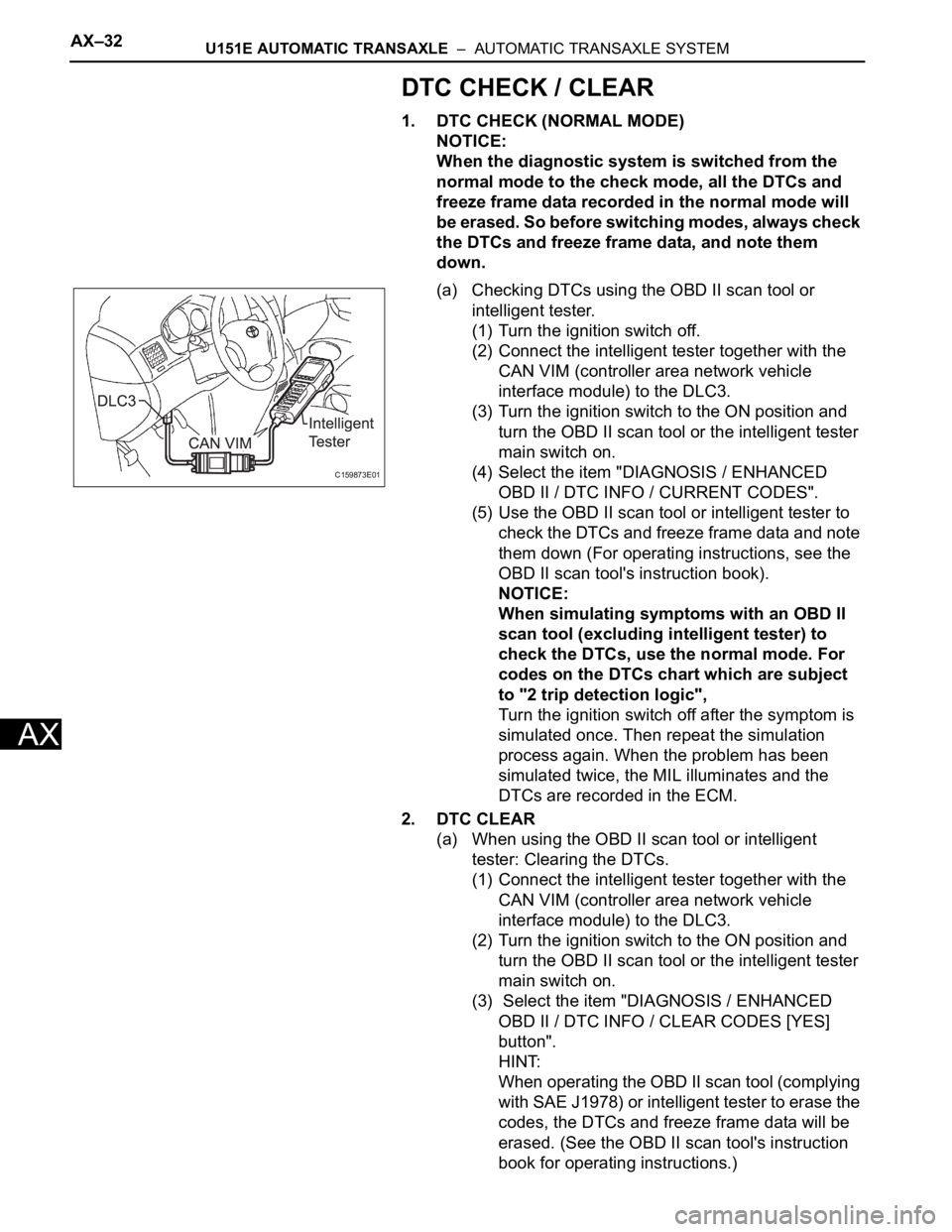
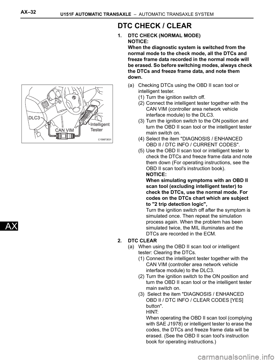
(2) Connect the intelligent tester together with the
CAN VIM (controller area network vehicle
interface module) to the DLC3.
(3) Turn the ignition switch to the ON position and
turn the OBD II scan tool or the intelligent tester
main switch on.
(4) Select the item "DIAGNOSIS / ENHANCED
OBD II / DTC INFO / CURRENT CODES".
(5) Use the OBD II scan tool or intelligent tester to
check the DTCs and freeze frame data and note
them down (For operating instructions, see the
OBD II scan tool's instruction book).
NOTICE:
When simulating symptoms with an OBD II
scan tool (excluding intelligent tester) to
check the DTCs, use the normal mode. For
codes on the DTCs chart which are subject
to "2 trip detection logic",
Turn the ignition switch off after the symptom is
simulated once. Then repeat the simulation
process again. When the problem has been
simulated twice, the MIL illuminates and the
DTCs are recorded in the ECM.
2. DTC CLEAR
(a) When using the OBD II scan tool or intelligent
tester: Clearing the DTCs.
(1) Connect the intelligent tester together with the
CAN VIM (controller area network vehicle
interface module) to the DLC3.
(2) Turn the ignition switch to the ON position and
turn the OBD II scan tool or the intelligent tester
main switch on.
(3) Select the item "DIAGNOSIS / ENHANCED
OBD II / DTC INFO / CLEAR CODES [YES]
button".
HINT:
When operating the OBD II scan tool (complying
with SAE J1978) or intelligent tester to erase the
codes, the DTCs and freeze frame data will be
erased. (See the OBD II scan tool's instruction
book for operating instructions.)
C159873E01
Page 1708 of 3000
AX–32U151F AUTOMATIC TRANSAXLE – AUTOMATIC TRANSAXLE SYSTEM
AX
DTC CHECK / CLEAR
1. DTC CHECK (NORMAL MODE)
NOTICE:
When the diagnostic system is switched from the
normal mode to the check mode, all the DTCs and
freeze frame data recorded in the normal mode will
be erased. So before switching modes, always check
the DTCs and freeze frame data, and note them
down.
(a) Checking DTCs using the OBD II scan tool or
intelligent tester.
(1) Turn the ignition switch off.
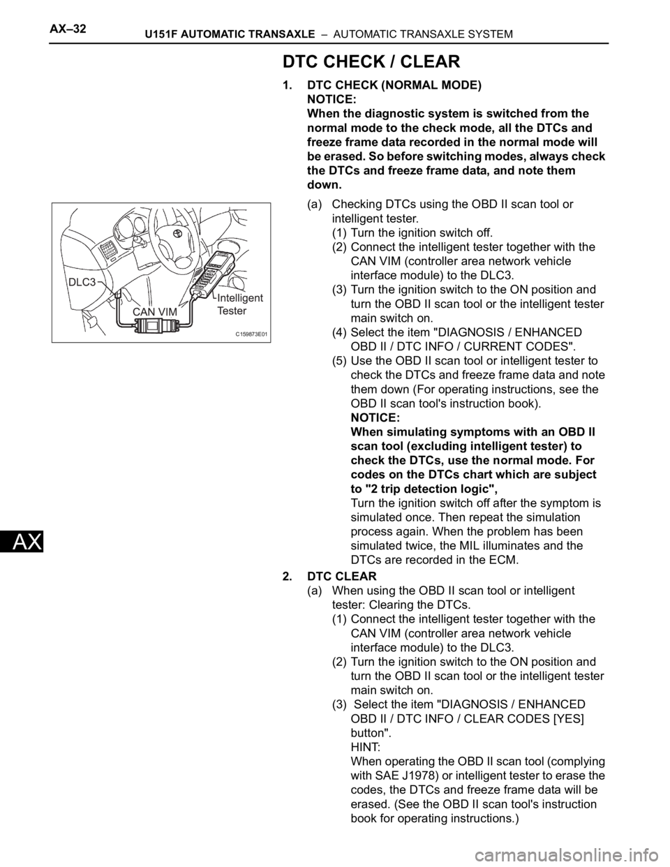
(2) Connect the intelligent tester together with the
CAN VIM (controller area network vehicle
interface module) to the DLC3.
(3) Turn the ignition switch to the ON position and
turn the OBD II scan tool or the intelligent tester
main switch on.
(4) Select the item "DIAGNOSIS / ENHANCED
OBD II / DTC INFO / CURRENT CODES".
(5) Use the OBD II scan tool or intelligent tester to
check the DTCs and freeze frame data and note
them down (For operating instructions, see the
OBD II scan tool's instruction book).
NOTICE:
When simulating symptoms with an OBD II
scan tool (excluding intelligent tester) to
check the DTCs, use the normal mode. For
codes on the DTCs chart which are subject
to "2 trip detection logic",
Turn the ignition switch off after the symptom is
simulated once. Then repeat the simulation
process again. When the problem has been
simulated twice, the MIL illuminates and the
DTCs are recorded in the ECM.
2. DTC CLEAR
(a) When using the OBD II scan tool or intelligent
tester: Clearing the DTCs.
(1) Connect the intelligent tester together with the
CAN VIM (controller area network vehicle
interface module) to the DLC3.
(2) Turn the ignition switch to the ON position and
turn the OBD II scan tool or the intelligent tester
main switch on.
(3) Select the item "DIAGNOSIS / ENHANCED
OBD II / DTC INFO / CLEAR CODES [YES]
button".
HINT:
When operating the OBD II scan tool (complying
with SAE J1978) or intelligent tester to erase the
codes, the DTCs and freeze frame data will be
erased. (See the OBD II scan tool's instruction
book for operating instructions.)
C159873E01
Page 1710 of 3000
AX–34U151F AUTOMATIC TRANSAXLE – AUTOMATIC TRANSAXLE SYSTEM
AX
CHECK MODE PROCEDURE
HINT:
Check mode has a higher sensitivity to malfunctions and can
detect malfunction that normal mode cannot detect. Check
mode can also detect all the malfunctions that normal mode
can detect. In check mode, DTCs are detected with 1-trip
detection logic.
1. DTC CHECK (CHECK MODE)
HINT:
Intelligent tester only: Compared to the normal mode, the
check mode is more sensitive for detecting malfunctions.
Furthermore, the same diagnostic items which are
detected in the normal mode can also be detected in the
check mode.
(a) Procedure for Check Mode using the intelligent
tester.
(1) Check the initial conditions.
• Battery positive voltage 11 V or more
• Throttle valve fully closed
• Transaxle in the P or N position
• A/C switch is off
(2) Turn the ignition switch off.
(3) Connect the intelligent tester together with the
CAN VIM (controller area network vehicle
interface module) to the DLC3.
(4) Turn the ignition switch to ON position and turn
the intelligent tester main switch on.
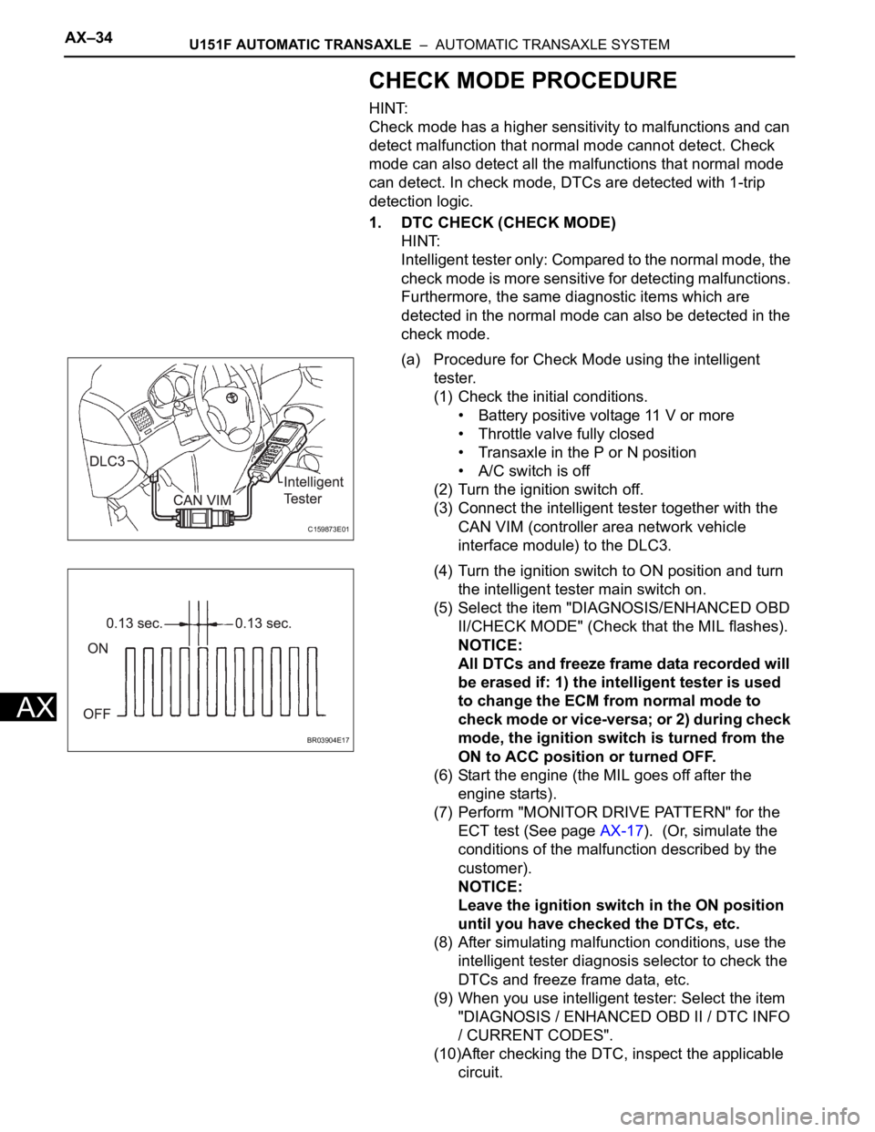
(5) Select the item "DIAGNOSIS/ENHANCED OBD
II/CHECK MODE" (Check that the MIL flashes).
NOTICE:
All DTCs and freeze frame data recorded will
be erased if: 1) the intelligent tester is used
to change the ECM from normal mode to
check mode or vice-versa; or 2) during check
mode, the ignition switch is turned from the
ON to ACC position or turned OFF.
(6) Start the engine (the MIL goes off after the
engine starts).
(7) Perform "MONITOR DRIVE PATTERN" for the
ECT test (See page AX-17). (Or, simulate the
conditions of the malfunction described by the
customer).
NOTICE:
Leave the ignition switch in the ON position
until you have checked the DTCs, etc.
(8) After simulating malfunction conditions, use the
intelligent tester diagnosis selector to check the
DTCs and freeze frame data, etc.
(9) When you use intelligent tester: Select the item
"DIAGNOSIS / ENHANCED OBD II / DTC INFO
/ CURRENT CODES".
(10)After checking the DTC, inspect the applicable
circuit.
C159873E01
BR03904E17
Page 1712 of 3000

AX–36U151F AUTOMATIC TRANSAXLE – AUTOMATIC TRANSAXLE SYSTEM
AX
FAIL-SAFE CHART
1. FAIL-SAFE
This function minimizes the loss of the ECT functions
when any malfunction occurs in a sensor or solenoid.
(a) ATF (Automatic Transmission Fluid) temperature
sensor:
When the ATF temperature sensor has a
malfunction, 5th upshift is prohibited.
(b) Counter gear speed sensor NC (Speed sensor NC):
When the counter gear speed sensor has a
malfunction, 5th upshift is prohibited.
(c) Shift solenoid valve DSL:
When the solenoid valve DSL has a malfunction, the
current to the solenoid valve is stopped.
This stops lock-up control, then fuel economy
decreases.
(d) Shift solenoid valve SL1, SL2, SL3 and S4:
Fail safe function:
If either of the shift solenoid valve circuits develops
an open or short, the ECM turns the other shift
solenoid "ON" and "OFF" in order to shift into the
gear positions shown in the table below.
Manual shifting as shown in the following table must
be done (In case of a short circuit, the ECM stops
sending the current to the short circuited solenoid).
Even if starting the engine in the fail-safe mode, the
gear position remains in the same position.
HINT:
FL: Flex Lock-up
NormalSolenoid ValveSL1 ON OFF ON OFF OFF
SL2 ON ON OFF FL FL
SL3 OFF OFF OFF ON ON
S4 OFF OFF OFF OFF ON
Gear Position 1st 2nd 3rd 4th 5th
SL1
Malfunction
(During driving
at 1st or 2nd)Solenoid ValveSL1 OFF
SL2 ON ON OFF to ON FL to ON FL to ON
SL3 OFF OFF OFF ON to OFF ON to OFF
S4 OFF OFF OFF OFF ON to OFF
Gear Position 1st to 2nd 2nd 3rd to 2nd 4th to 2nd 5th to 2nd
SL1
Malfunction
(During driving
at 3rd)Solenoid ValveSL1 OFF
SL2 ON to FL ON to FL OFF to FL FL FL
SL3 OFF OFF OFF ON to OFF ON to OFF
S4 OFF to ON OFF to ON OFF to ON OFF to ON ON
Gear Position 1st to 4th 2nd to 4th 3rd to 4th 4th 5th to 4th
SL1
Malfunction
(During driving
at 4th or 5th)Solenoid ValveSL1 OFF
SL2 ON to FL ON to FL OFF to FL FL FL
SL3 OFF to ON OFF to ON OFF to ON ON ON
S4 OFF OFF OFF OFF ON
Gear Position 1st to 4th 2nd to 4th 3rd to 4th 4th 5th to 4th
Page 1845 of 3000
U151F AUTOMATIC TRANSAXLE – AUTOMATIC TRANSAXLE SYSTEMAX–29
AX
DIAGNOSIS SYSTEM
1. DESCRIPTION
(a) When troubleshooting OBD II vehicles, the only
difference from the usual troubleshooting procedure
is to connect an OBD II scan tool complying with
SAE J1987 or a intelligent tester to the vehicle, and
read off various data output from the vehicle's ECM.
(b) OBD II regulations require that the vehicle's on-
board computer illuminate the Malfunction Indicator
Lamp (MIL) on the instrument panel when the
computer detects a malfunction in the computer
itself or in the drive system components whic h affect
the vehicle emissions. In addition to illuminating the
MIL when a malfunction is detected, the applicable
DTCs prescribed by SAE J2012 are recorded in the
ECM memory (See page AX-35).
If the malfunction does not occur in 3 consecutive
trips, the MIL goes off but the DTCs remain in the
ECM memory.
(c) To check the DTCs, connect the OBD II scan tool or
intelligent tester to the DLC3 of the vehicle. The
OBD II scan tool or intelligent tester also enables
you to erase the DTCs and check freeze frame data
and various forms of engine data (For operating
instructions, see the instruction book).
(d) The DTCs include SAE controlled codes and
Manufacturer controlled codes. SAE controlled
codes must be set as prescribed by the SAE, while
Manufacturer controlled codes can be set freely by
a manufacturer within the prescribed limits (See
page AX-35).
(e) The diagnosis system operates in "normal mode"
during the normal vehicle use. In normal mode, "2-
trip detection logic" is used to ensure accurate
detection of malfunction. "Check mode" is also
available to technicians as an option. In check
mode, "1-trip detection logic" is used for simulating
malfunction symptoms and increasing the system's
ability to detect malfunctions, including intermittent
malfunction.
(f) *2 trip detection logic: When a malfunction is first
detected, the malfunction is temporarily stored in
the ECM memory (1st trip). If the ignition switch is
turned off and then turned to the ON position again,
and same malfunction is detected again, the MIL will
illuminate.
FI00534
C159873E01
Page 1854 of 3000
AX–32U151F AUTOMATIC TRANSAXLE – AUTOMATIC TRANSAXLE SYSTEM
AX
DTC CHECK / CLEAR
1. DTC CHECK (NORMAL MODE)
NOTICE:
When the diagnostic system is switched from the
normal mode to the check mode, all the DTCs and
freeze frame data recorded in the normal mode will
be erased. So before switching modes, always check
the DTCs and freeze frame data, and note them
down.
(a) Checking DTCs using the OBD II scan tool or
intelligent tester.
(1) Turn the ignition switch off.
(2) Connect the intelligent tester together with the
CAN VIM (controller area network vehicle
interface module) to the DLC3.
(3) Turn the ignition switch to the ON position and
turn the OBD II scan tool or the intelligent tester
main switch on.
(4) Select the item "DIAGNOSIS / ENHANCED
OBD II / DTC INFO / CURRENT CODES".
(5) Use the OBD II scan tool or intelligent tester to
check the DTCs and freeze frame data and note
them down (For operating instructions, see the
OBD II scan tool's instruction book).
NOTICE:
When simulating symptoms with an OBD II
scan tool (excluding intelligent tester) to
check the DTCs, use the normal mode. For
codes on the DTCs chart which are subject
to "2 trip detection logic",
Turn the ignition switch off after the symptom is
simulated once. Then repeat the simulation
process again. When the problem has been
simulated twice, the MIL illuminates and the
DTCs are recorded in the ECM.
2. DTC CLEAR
(a) When using the OBD II scan tool or intelligent
tester: Clearing the DTCs.
(1) Connect the intelligent tester together with the
CAN VIM (controller area network vehicle
interface module) to the DLC3.
(2) Turn the ignition switch to the ON position and
turn the OBD II scan tool or the intelligent tester
main switch on.
(3) Select the item "DIAGNOSIS / ENHANCED
OBD II / DTC INFO / CLEAR CODES [YES]
button".
HINT:
When operating the OBD II scan tool (complying
with SAE J1978) or intelligent tester to erase the
codes, the DTCs and freeze frame data will be
erased. (See the OBD II scan tool's instruction
book for operating instructions.)
C159873E01
Page 2186 of 3000
SP–4SUSPENSION – FRONT WHEEL ALIGNMENT
SP
FRONT WHEEL ALIGNMENT
ADJUSTMENT
NOTICE:
For vehicles equipped with VSC, if wheel alignment has
been adjusted, and if suspension or underbody
components have been removed/installed or replaced, be
sure to perform the following initialization procedure in
order for the system to function normally:
1. Disconnect the negative battery terminal for more
than 2 seconds.
2. Reconnect the negative battery terminal.
3. Perform zero point calibration of the yaw rate and
acceleration sensor and test mode inspection.
HINT:
(See page BC-70)
1. INSPECT TIRE
HINT:
(See page TW-2)
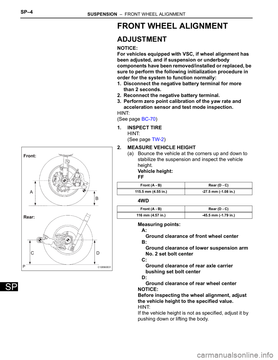
2. MEASURE VEHICLE HEIGHT
(a) Bounce the vehicle at the corners up and down to
stabilize the suspension and inspect the vehicle
height.
Vehicle height:
FF
4WD
Measuring points:
A:
Ground clearance of front wheel center
B:
Ground clearance of lower suspension arm
No. 2 set bolt center
C:
Ground clearance of rear axle carrier
bushing set bolt center
D:
Ground clearance of rear wheel center
NOTICE:
Before inspecting the wheel alignment, adjust
the vehicle height to the specified value.
HINT:
If the vehicle height is not as specified, adjust it by
pushing down or lifting the body.
C128560E01
Front (A - B) Rear (D - C)
115.5 mm (4.55 in.) -27.5 mm (-1.08 in.)
Front (A - B) Rear (D - C)
116 mm (4.57 in.) -45.5 mm (-1.79 in.)