2007 TOYOTA SIENNA ECO mode
[x] Cancel search: ECO modePage 360 of 3000

ES–422GR-FE ENGINE CONTROL SYSTEM – SFI SYSTEM
ES
In order to enhance OBD function on vehicles and
develop the Off-Board diagnosis system, CAN
communication is introduced in this system (CAN:
Controller Area Network). It minimizes a gap
between technician skills and vehicle technology.
CAN is a network, which uses a pair of data
transmission lines, spanning multiple computers
and sensors. It allows a high speed communication
between the systems and to simplify the wire
harness connection.
Since this system is equipped with the CAN
communication, connecting the CAN VIM (VIM:
Vehicle Interface Module) with an intelligent tester is
necessary to display any information from the ECM.
(Also the communication between the intelligent
tester and the ECM uses CAN communication
signal.) When confirming the DTCs and any data of
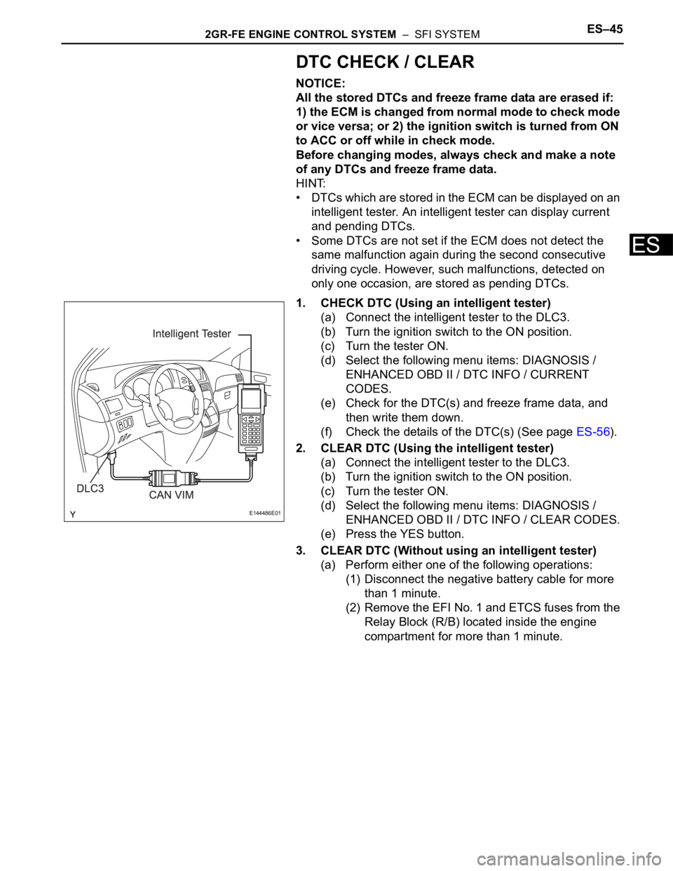
the ECM, connect the CAN VIM between the DLC3
and the intelligent tester.
2. NORMAL MODE AND CHECK MODE
(a) The diagnosis system operates in normal mode
during normal vehicle use. In normal mode, 2 trip
detection logic is used to ensure accurate detection
of malfunctions. Check mode is also available as an
option for technicians. In check mode, 1 trip
detection logic is used for simulating malfunction
symptoms and increasing the system's ability to
detect malfunctions, including intermittent problems
(intelligent tester only) (See page ES-43).
3. 2 TRIP DETECTION LOGIC
(a) When a malfunction is first detected, the
malfunction is temporarily stored in the ECM
memory (1st trip). If the same malfunction is
detected during the next subsequent drive cycle, the
MIL is illuminated (2nd trip).
4. FREEZE FRAME DATA
(a) The ECM records vehicle and driving condition
information as freeze frame data the moment a DTC
is stored. When troubleshooting, freeze frame data
can be helpful in determining whether the vehicle
was running or stopped, whether the engine was
warmed up or not, whether the air-fuel ratio was
lean or rich, as well as other data recorded at the
time of a malfunction.
A082779E02
Page 363 of 3000

2GR-FE ENGINE CONTROL SYSTEM – SFI SYSTEMES–45
ES
DTC CHECK / CLEAR
NOTICE:
All the stored DTCs and freeze frame data are erased if:
1) the ECM is changed from normal mode to check mode
or vice versa; or 2) the ignition switch is turned from ON
to ACC or off while in check mode.
Before changing modes, always check and make a note
of any DTCs and freeze frame data.
HINT:
• DTCs which are stored in the ECM can be displayed on an
intelligent tester. An intelligent tester can display current
and pending DTCs.
• Some DTCs are not set if the ECM does not detect the
same malfunction again during the second consecutive
driving cycle. However, such malfunctions, detected on
only one occasion, are stored as pending DTCs.
1. CHECK DTC (Using an intelligent tester)
(a) Connect the intelligent tester to the DLC3.
(b) Turn the ignition switch to the ON position.
(c) Turn the tester ON.
(d) Select the following menu items: DIAGNOSIS /
ENHANCED OBD II / DTC INFO / CURRENT
CODES.
(e) Check for the DTC(s) and freeze frame data, and
then write them down.
(f) Check the details of the DTC(s) (See page ES-56).
2. CLEAR DTC (Using the intelligent tester)
(a) Connect the intelligent tester to the DLC3.
(b) Turn the ignition switch to the ON position.
(c) Turn the tester ON.
(d) Select the following menu items: DIAGNOSIS /
ENHANCED OBD II / DTC INFO / CLEAR CODES.
(e) Press the YES button.
3. CLEAR DTC (Without using an intelligent tester)
(a) Perform either one of the following operations:
(1) Disconnect the negative battery cable for more
than 1 minute.
(2) Remove the EFI No. 1 and ETCS fuses from the
Relay Block (R/B) located inside the engine
compartment for more than 1 minute.
E144486E01
Page 413 of 3000

2GR-FE ENGINE CONTROL SYSTEM – SFI SYSTEMES–107
ES
MONITOR STRATEGY
TYPICAL ENABLING CONDITIONS
All:
P0016 and P0018:
P0017 and P0019:
TYPICAL MALFUNCTION THRESHOLDS
P0016 and P0018:
P0017 and P0019:
WIRING DIAGRAM
Refer to DTC P0335 (See page ES-222).
INSPECTION PROCEDURE
HINT:
Read freeze frame data using the intelligent tester. The ECM records vehicle and driving condition
information as freeze frame data the moment a DTC is stored. When troubleshooting, freeze frame data
can be helpful in determining whether the vehicle was running or stopped, whether the engine was
warmed up or not, whether the air-fuel ratio was lean or rich, as well as other data recorded at the time of
a malfunction.
Related DTCsP0016: Deviation in crankshaft position sensor signal and camshaft position sensor
signal (Bank 1)
P0017: Deviation in crankshaft position sensor signal and camshaft position sensor
signal (Bank 1 Sensor 2)
P0018: Deviation in crankshaft position sensor signal and camshaft position sensor
signal (Bank 2)
P0019: Deviation in crankshaft position sensor signal and camshaft position sensor
signal (Bank 2 Sensor 2)
Required Sensors / Components (Main)P0016 and P0018: VVT actuator
P0017 and P0019: Timing chain/belt
Required Sensors / Components (Related)P0016 and P0018: Camshaft position sensor, Crankshaft position sensor
P0017 and P0019: None
Frequency of Operation Once per driving cycle
Duration Less than 60 seconds
MIL Operation 2 driving cycles
Sequence of Operation None
The monitor will run whenever these DTCs are not
presentP0011, P0012 (VVT System 1-Advance, Retard), P0021, P0022 (VVT System 2-
Adavance, Retard), P0115, P0116, P0117, P0118 (ECT Sensor)
Engine RPM 500 to 1000 rpm
VVT feedback mode Executing
VVT Maximum advanced position
Engine RPM 500 to 1000 rpm
One of the following conditions is met: Condition 1 or 2
1. VVT learning value at maximum retarded valve
timingLess than 18.5
CA
2. VVT learning value at maximum retarded valve
timingMore than 43.5
CA
One of the following conditions is met: Condition 1 or 2
1. VVT learning value Less than 77
CA
2. VVT learning value More than 102
CA
Page 418 of 3000

ES–1122GR-FE ENGINE CONTROL SYSTEM – SFI SYSTEM
ES
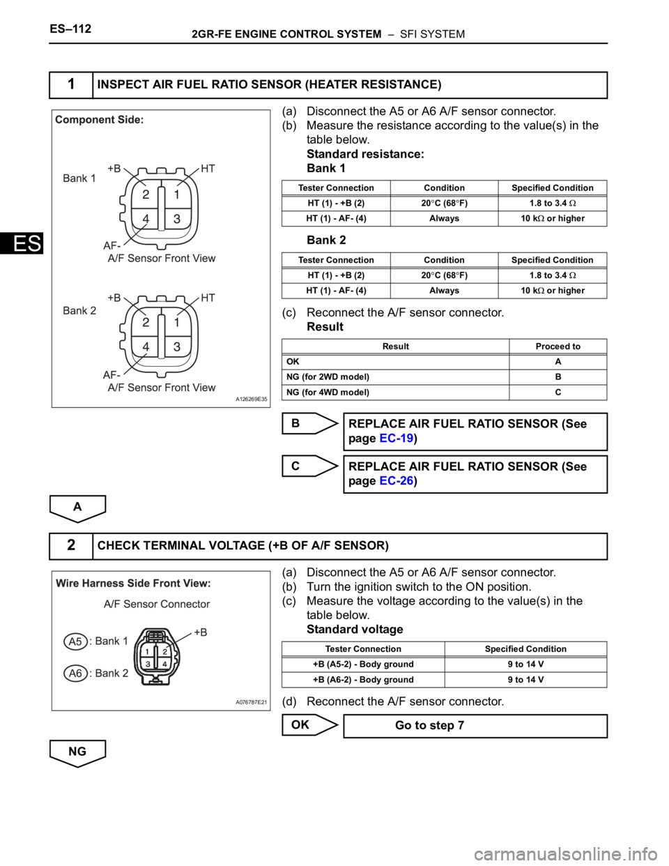
(a) Disconnect the A5 or A6 A/F sensor connector.
(b) Measure the resistance according to the value(s) in the
table below.
Standard resistance:
Bank 1
Bank 2
(c) Reconnect the A/F sensor connector.
Result
B
C
A
(a) Disconnect the A5 or A6 A/F sensor connector.
(b) Turn the ignition switch to the ON position.
(c) Measure the voltage according to the value(s) in the
table below.
Standard voltage
(d) Reconnect the A/F sensor connector.
OK
NG
1INSPECT AIR FUEL RATIO SENSOR (HEATER RESISTANCE)
A126269E35
Tester Connection Condition Specified Condition
HT (1) - +B (2) 20
C (68F) 1.8 to 3.4
HT (1) - AF- (4) Always 10 k or higher
Tester Connection Condition Specified Condition
HT (1) - +B (2) 20
C (68F) 1.8 to 3.4
HT (1) - AF- (4) Always 10 k or higher
Result Proceed to
OK A
NG (for 2WD model) B
NG (for 4WD model) C
REPLACE AIR FUEL RATIO SENSOR (See
page EC-19)
REPLACE AIR FUEL RATIO SENSOR (See
page EC-26)
2CHECK TERMINAL VOLTAGE (+B OF A/F SENSOR)
A076787E21
Tester Connection Specified Condition
+B (A5-2) - Body ground 9 to 14 V
+B (A6-2) - Body ground 9 to 14 V
Go to step 7
Page 430 of 3000

ES–1242GR-FE ENGINE CONTROL SYSTEM – SFI SYSTEM
ES
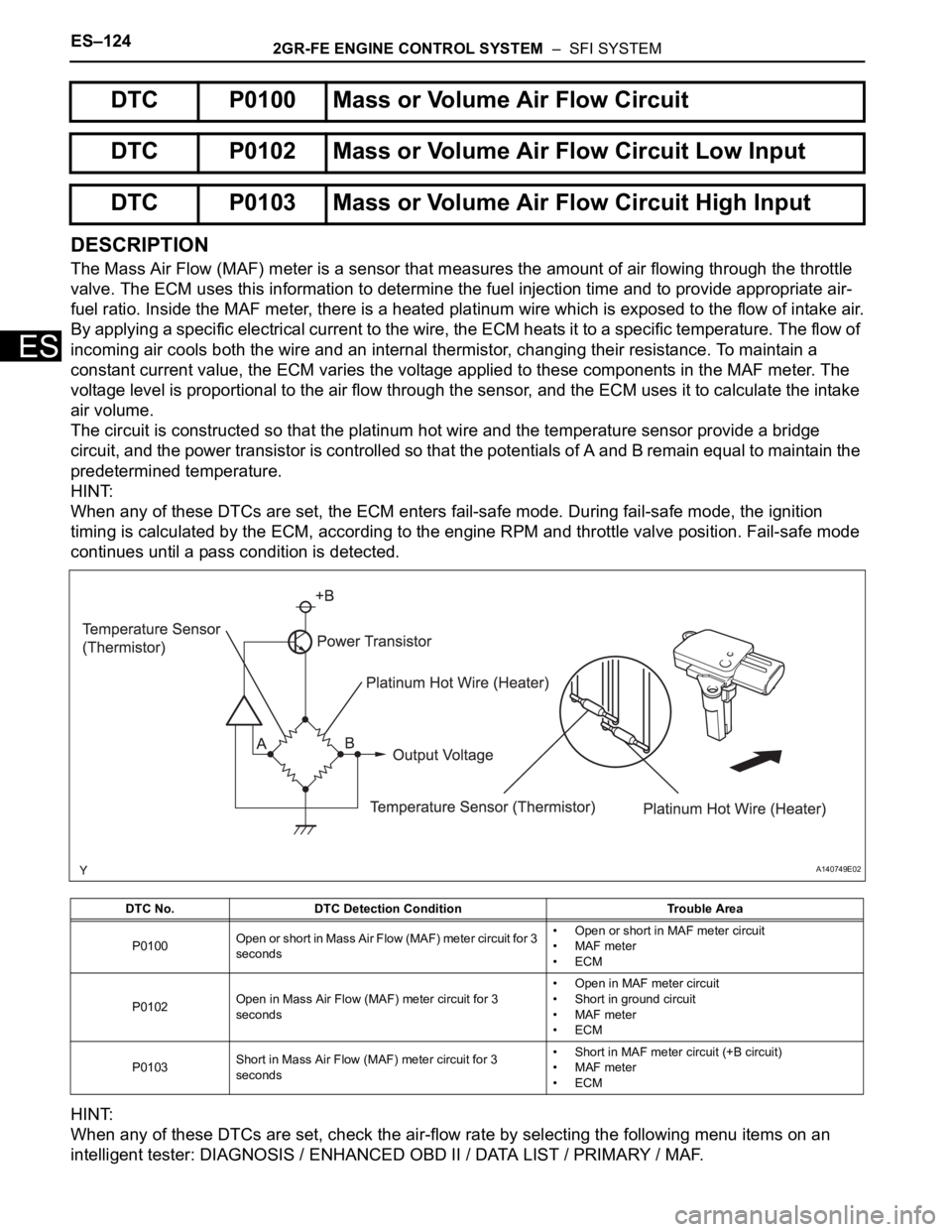
DESCRIPTION
The Mass Air Flow (MAF) meter is a sensor that measures the amount of air flowing through the throttle
valve. The ECM uses this information to determine the fuel injection time and to provide appropriate air-
fuel ratio. Inside the MAF meter, there is a heated platinum wire which is exposed to the flow of intake air.
By applying a specific electrical current to the wire, the ECM heats it to a specific temperature. The flow of
incoming air cools both the wire and an internal thermistor, changing their resistance. To maintain a
constant current value, the ECM varies the voltage applied to these components in the MAF meter. The
voltage level is proportional to the air flow through the sensor, and the ECM uses it to calculate the intake
air volume.
The circuit is constructed so that the platinum hot wire and the temperature sensor provide a bridge
circuit, and the power transistor is controlled so that the potentials of A and B remain equal to maintain the
predetermined temperature.
HINT:
When any of these DTCs are set, the ECM enters fail-safe mode. During fail-safe mode, the ignition
timing is calculated by the ECM, according to the engine RPM and throttle valve position. Fail-safe mode
continues until a pass condition is detected.
HINT:
When any of these DTCs are set, check the air-flow rate by selecting the following menu items on an
intelligent tester: DIAGNOSIS / ENHANCED OBD II / DATA LIST / PRIMARY / MAF.
DTC P0100 Mass or Volume Air Flow Circuit
DTC P0102 Mass or Volume Air Flow Circuit Low Input
DTC P0103 Mass or Volume Air Flow Circuit High Input
DTC No. DTC Detection Condition Trouble Area
P0100Open or short in Mass Air Flow (MAF) meter circuit for 3
seconds• Open or short in MAF meter circuit
• MAF meter
•ECM
P0102Open in Mass Air Flow (MAF) meter circuit for 3
seconds• Open in MAF meter circuit
• Short in ground circuit
• MAF meter
•ECM
P0103Short in Mass Air Flow (MAF) meter circuit for 3
seconds• Short in MAF meter circuit (+B circuit)
• MAF meter
•ECM
A140749E02
Page 438 of 3000

ES–1322GR-FE ENGINE CONTROL SYSTEM – SFI SYSTEM
ES
DESCRIPTION
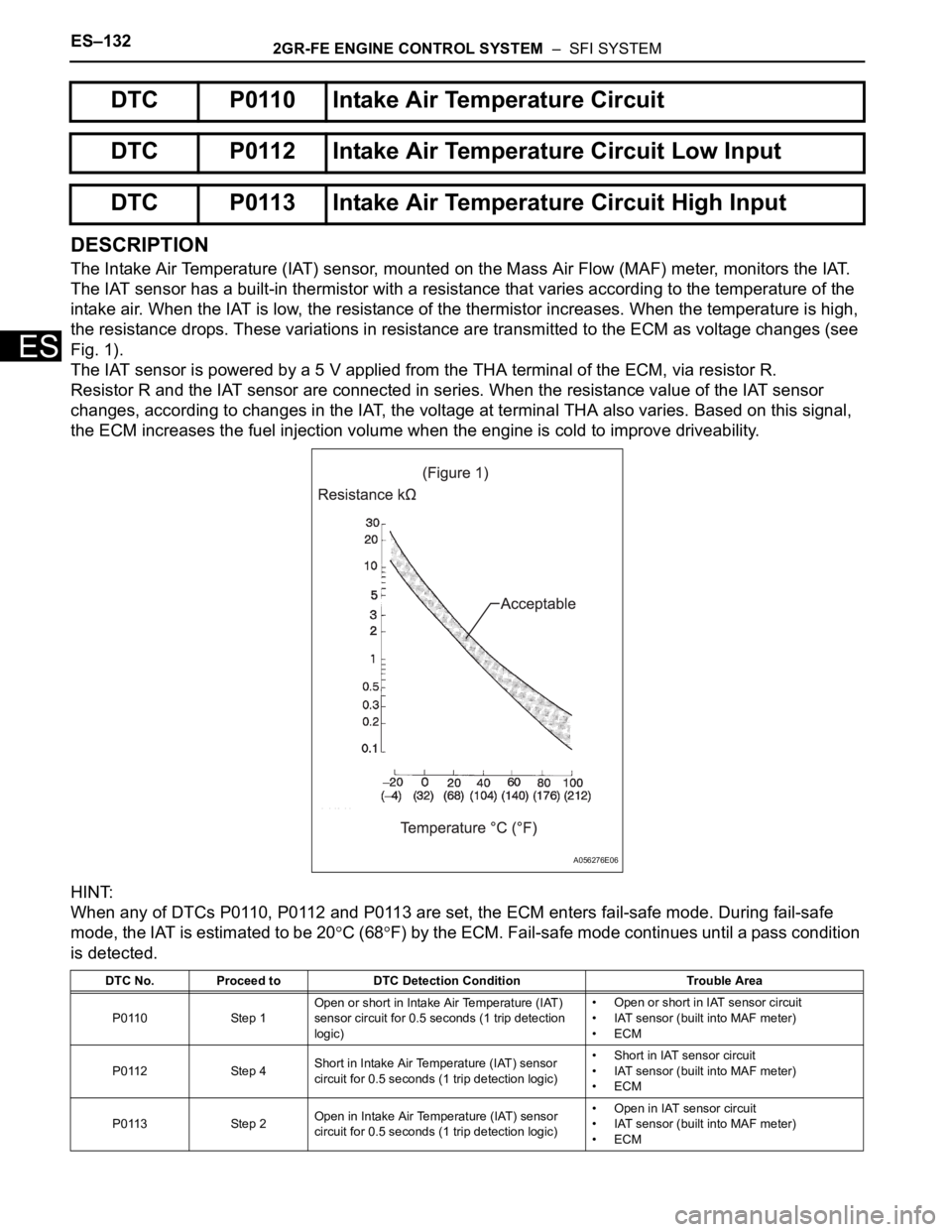
The Intake Air Temperature (IAT) sensor, mounted on the Mass Air Flow (MAF) meter, monitors the IAT.
The IAT sensor has a built-in thermistor with a resistance that varies according to the temperature of the
intake air. When the IAT is low, the resistance of the thermistor increases. When the temperature is high,
the resistance drops. These variations in resistance are transmitted to the ECM as voltage changes (see
Fig. 1).
The IAT sensor is powered by a 5 V applied from the THA terminal of the ECM, via resistor R.
Resistor R and the IAT sensor are connected in series. When the resistance value of the IAT sensor
changes, according to changes in the IAT, the voltage at terminal THA also varies. Based on this signal,
the ECM increases the fuel injection volume when the engine is cold to improve driveability.
HINT:
When any of DTCs P0110, P0112 and P0113 are set, the ECM enters fail-safe mode. During fail-safe
mode, the IAT is estimated to be 20
C (68F) by the ECM. Fail-safe mode continues until a pass condition
is detected.
DTC P0110 Intake Air Temperature Circuit
DTC P0112 Intake Air Temperature Circuit Low Input
DTC P0113 Intake Air Temperature Circuit High Input
DTC No. Proceed to DTC Detection Condition Trouble Area
P0110 Step 1Open or short in Intake Air Temperature (IAT)
sensor circuit for 0.5 seconds (1 trip detection
logic)• Open or short in IAT sensor circuit
• IAT sensor (built into MAF meter)
•ECM
P0112 Step 4Short in Intake Air Temperature (IAT) sensor
circuit for 0.5 seconds (1 trip detection logic)• Short in IAT sensor circuit
• IAT sensor (built into MAF meter)
•ECM
P0113 Step 2Open in Intake Air Temperature (IAT) sensor
circuit for 0.5 seconds (1 trip detection logic)• Open in IAT sensor circuit
• IAT sensor (built into MAF meter)
•ECM
A056276E06
Page 447 of 3000

2GR-FE ENGINE CONTROL SYSTEM – SFI SYSTEMES–141
ES
DESCRIPTION
A thermistor is built into the Engine Coolant Temperature (ECT) sensor, of which the resistance value
varies according to the ECT.
The structure of the sensor and its connection to the ECM are the same as those of the Intake Air
Temperature (IAT) sensor.
HINT:
When any of DTCs P0115, P0117 and P0118 are set, the ECM enters fail-safe mode. During fail-safe
mode, the ECT is estimated to be 80
C (176F) by the ECM. Fail-safe mode continues until a pass
condition is detected.
HINT:
When any of these DTCs are set, check the ECT by selecting the following menu items on the intelligent
tester: DIAGNOSIS / ENHANCED OBD II / DATA LIST / PRIMARY / COOLANT TEMP.
MONITOR DESCRIPTION
The Engine Coolant Temperature (ECT) sensor is used to monitor the ECT. The ECT sensor has a
thermistor with a resistance that varies according to the temperature of the engine coolant. When the
coolant temperature becomes low, the resistance in the thermistor increases. When the temperature
becomes high, the resistance drops.
These variations in resistance are reflected in the voltage output from the sensor. The ECM monitors the
sensor voltage and uses this value to calculate the ECT. When the sensor output voltage deviates from
the normal operating range, the ECM interprets this as a fault in the ECT sensor and sets a DTC.
Example:
If the sensor voltage output is -40
C (-40F) for 0.5 seconds or more, the ECM determines that there is an
open in the ECT sensor circuit, and sets DTC P0118. Conversely, if the voltage output is more than 140
C
(284
F) for 0.5 seconds or more, the ECM determines that there is a short in the sensor circuit, and sets
DTC P0117.
If the malfunction is not repaired successfully, a DTC is set 0.5 seconds after the engine is next started.
MONITOR STRATEGY
DTC P0115 Engine Coolant Temperature Circuit
DTC P0117 Engine Coolant Temperature Circuit Low Input
DTC P0118 Engine Coolant Temperature Circuit High Input
DTC No. Proceed to DTC Detection Condition Trouble Area
P0115 Step 1Open or short in Engine Coolant Temperature
(ECT) sensor circuit for 0.5 seconds (1 trip
detection logic)• Open or short in ECT sensor circuit
• ECT sensor
•ECM
P0117 Step 4Short in Engine Coolant Temperature (ECT)
sensor circuit for 0.5 seconds (1 trip detection
logic)• Short in ECT sensor circuit
• ECT sensor
•ECM
P0118 Step 2Open in Engine Coolant Temperature (ECT)
sensor circuit for 0.5 seconds (1 trip detection
logic)• Open in ECT sensor circuit
• ECT sensor
•ECM
Temperature Displayed Malfunctions
-40
C (-40F) Open circuit
140
C (284F) or higher Short circuit
Related DTCsP0115: Engine coolant temperature sensor open/short (Fluctuating)
P0117: Engine coolant temperature sensor short (Low electrical voltage)
P0118: Engine coolant temperature sensor open (High electrical voltage)
Page 467 of 3000

2GR-FE ENGINE CONTROL SYSTEM – SFI SYSTEMES–161
ES
FAIL-SAFE
When this DTC, as well as other DTCs relating to ETCS (Electronic Throttle Control System)
malfunctions, is set, the ECM enters fail-safe mode. During fail-safe mode, the ECM cuts the current to
the throttle actuator off, and the throttle valve is returned to a 6.5
throttle angle by the return spring. The
ECM then adjusts the engine output by controlling the fuel injection (intermittent fuel-cut) and ignition
timing, in accordance with the accelerator pedal opening angle, to allow the vehicle to continue at a
minimal speed. If the accelerator pedal is depressed slowly, the vehicle can be driven slowly.
Fail-safe mode continues until a pass condition is detected, and the ignition switch is then turned off.
INSPECTION PROCEDURE
HINT:
Read freeze frame data using the intelligent tester. The ECM records vehicle and driving condition
information as freeze frame data the moment a DTC is stored. When troubleshooting, freeze frame data
can be helpful in determining whether the vehicle was running or stopped, whether the engine was
warmed up or not, whether the air-fuel ratio was lean or rich, as well as other data recorded at the time of
a malfunction.
(a) Connect the intelligent tester to the DLC3.
(b) Turn the ignition switch to the ON position.
(c) Turn the tester ON.
(d) Enter the following menus: DIAGNOSIS / ENHANCED
OBD II / DTC INFO / CURRENT CODES.
(e) Read the DTC.
Result
HINT:
If any DTCs other than P0121 are output, troubleshoot
those DTCs first.
B
A
1CHECK ANY OTHER DTC OUTPUT (IN ADDITION TO DTC P0121)
Display (DTC output) Proceed to
P0121 A
P0121 and other DTCs B
GO TO DTC CHART
REPLACE THROTTLE BODY