2006 LAND ROVER FRELANDER 2 service
[x] Cancel search: servicePage 2546 of 3229
Publis hed: 11-May-2011
Front End Sheet Metal Repairs - Front Side Member and Suspension Top Mount
AssemblyRemoval and Ins tallat ion
Removal
• NO TE: The front s ide member and suspens ion t op mount as sembly is an ass embly of the front s ide member closing panel, fenderapron panel reinforcement, fender apron panel front ext ens ion, fender apron lower panel, front s ide member and fender apronpanel and the s uspens ion t op mount .
• NO TE: The service panel is not fully welded.
• NO TE: The panel is serviced les s it s weld s tuds
1. The front side member and suspens ion t op mount as sembly isreplaced in conjunct ion wit h:
Front bumper cover
Front bumper armat ure
Hood lat ch panel
Both front fenders
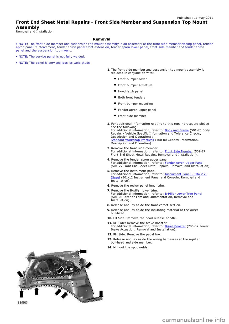
Front bumper mount ing
Fender apron upper panel
Front side member
2. For addit ional information relating t o t his repair procedure pleas es ee t he following:For addit ional informat ion, refer to: Body and Frame (501-26 BodyRepairs - Vehicle Specific Informat ion and Tolerance Checks ,Des cript ion and O perat ion) /Standard W orkshop Pract ices (100-00 General Informat ion,Des cript ion and O perat ion).
3. Remove t he front s ide member.For addit ional informat ion, refer to: Front Side Member (501-27Front End Sheet Met al Repairs, Removal and Ins t allat ion).
4. Remove t he fender apron upper panel.For addit ional informat ion, refer to: Fender Apron Upper Panel(501-27 Front End Sheet Met al Repairs, Removal and Ins t allat ion).
5. Remove t he ins t rument panel.For addit ional informat ion, refer to: Inst rument Panel - TD4 2.2LDiesel (501-12 Inst rument Panel and Cons ole, Removal andIns t allat ion).
6. Remove t he rocker panel inner t rim.
7. Remove t he B-pillar lower t rim.For addit ional informat ion, refer to: B-Pillar Lower Trim Panel(501-05 Int erior Trim and Ornamentat ion, Removal andIns t allat ion).
8. Releas e and lay as ide t he front carpet sect ion.
9. Releas e and lay as ide t he ins ulat ing mat erial at t he out erbulkhead.
10. LH Side: Remove the hood releas e handle.
11. RH Side: Remove the brake boost er.For addit ional informat ion, refer to: Brake Boost er (206-07 PowerBrake Act uat ion, Removal and Ins t allat ion).
12. RH Side: Remove the pedal box.
13. Release and lay aside t he wiring harnes ses at t he a-pillar,bulkhead and s ide member.
14. Mill out t he spot welds .
Page 2557 of 3229
Publ is hed: 11-May-2011
Front End Sheet Metal Repairs - Front Side Member Section
Removal and Installation
Removal
• NOTE: The front side member section is cut from the front side member service panel.
• NOTE: The RH section is slightly shorter than the LH due to the location of the engine mounting.
• NOTE: Due to the combined thickness of the panels, it is recommended that spot welds are replaced with MIG plug welds
in this repair.
1. The front s ide member s ect ion is replaced in conjunct ion wit h:
Front bumper cover
Front bumpe r a rma t ure
Hood lat ch panel
Both front fenders
Front bumpe r mount i ng
• NOTE: It is also necessary to remove the engine and suspension as an assembly.
2. Fo r a d d i t i o na l i nf o rma t i o n re l a t i ng t o t hi s re p a i r p ro ce d ure
please see the following:
Fo r a d d i t i o na l i nf o rma t i o n, re f e r t o : Body and Frame
(501-26
Body Repairs - Vehicle Specific Information and Tolerance
Checks, Description and Operation) /
St a nd a rd W o rks ho p P ra ct i ce s
(100-00 Ge ne ra l I nf o rma t i o n,
Description and Operation).
3. Re move t he f ront bumpe r mount i ng.
Fo r a d d i t i o na l i nf o rma t i o n, re f e r t o : Front Bumper Mount ing
(501-27 Front End Sheet Met al Re pai rs , Removal and
Installation).
4. Remove the radiator cooling pack.
Fo r a d d i t i o na l i nf o rma t i o n, re f e r t o : Radiator
(303-03A Engi ne
Cooling - I6 3.2L Petrol, Removal and Installation).
5. Remove the engine and front suspension as an assembly.
6. LH Side: Remove the air intake pipe.
7. LH Side: Release the battery junction box and position aside.
8. RH Side: Remove the windshield washer reservoir.
Fo r a d d i t i o na l i nf o rma t i o n, re f e r t o : Windshield Washer
Res ervoi r (501-16 W i pers and W as hers , Removal and
Installation).
9. Release and lay aside the wiring harness.
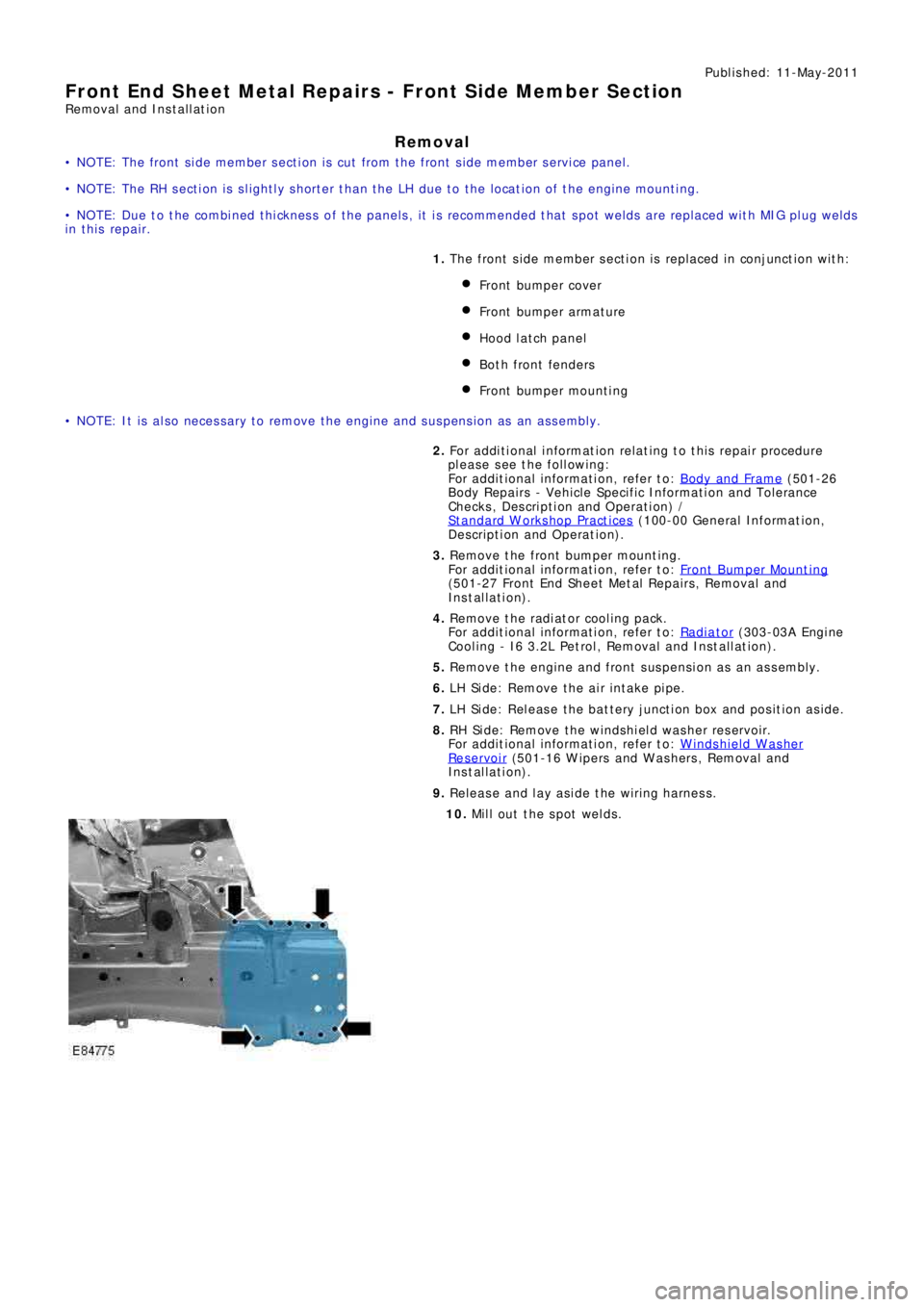
10. Mill out the spot welds.
Page 2558 of 3229
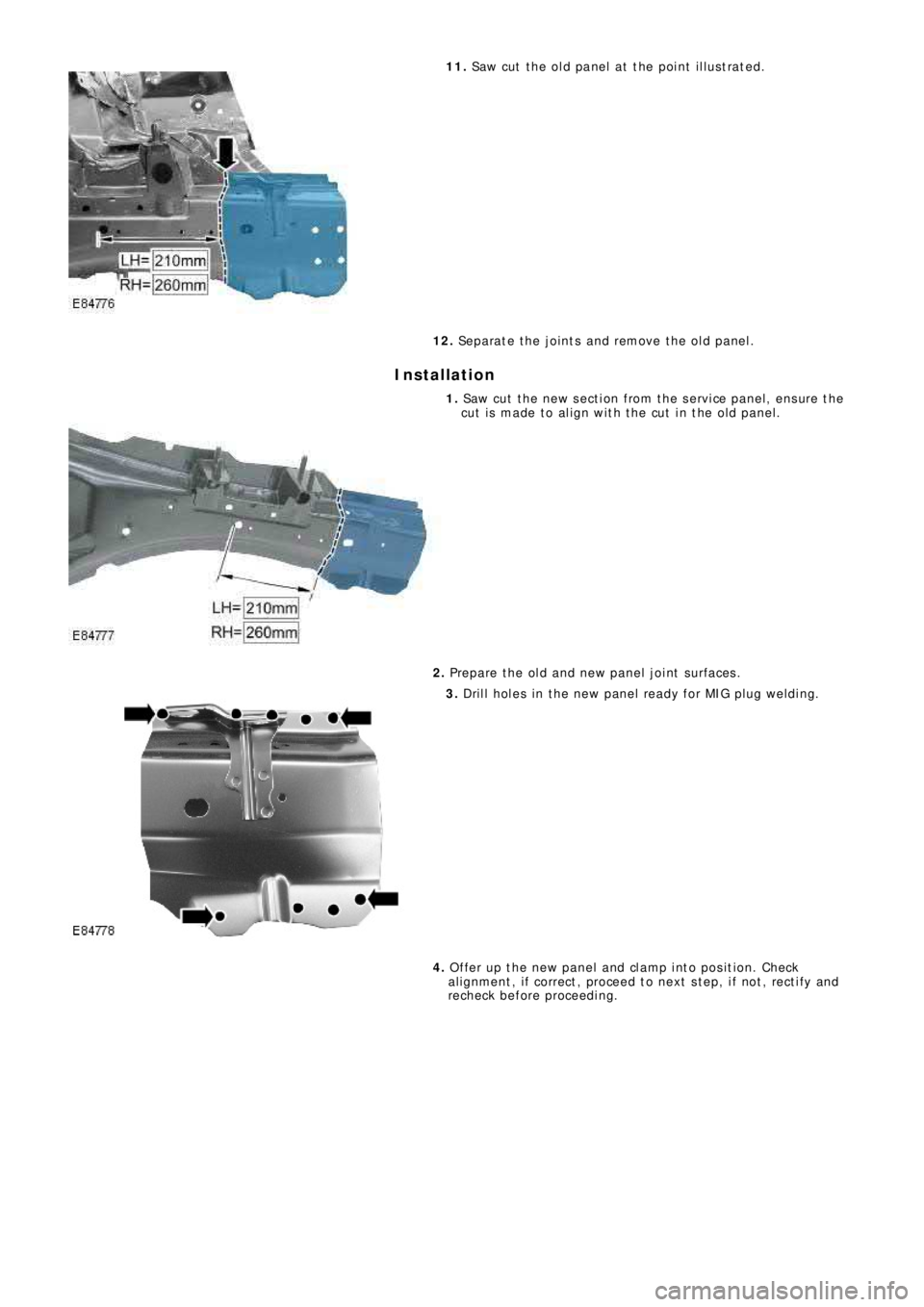
11. Saw cut the old panel at the point illustrated.
12. Separate the joints and remove the old panel.
Installation
1. Saw cut the new section from the service panel, ensure the
cut is made to align with the cut in the old panel.
2. Prepare the old and new panel joint surfaces.
3. Drill holes in the new panel ready for MIG plug welding.
4. Offer up the new panel and clamp into position. Check
al ignment , i f correct , proceed t o next s t ep, i f not , rect i fy and
recheck before proceeding.
Page 2560 of 3229

Publ is hed: 11-May-2011
Front End Sheet Metal Repairs - Fender Apron Panel
Removal and Installation
Removal
• NOTE: The fender apron panel is serviced as a separate weld-on panel. It is an assembly of the fender apron panel
reinforcement, fender apron lower panel and fender apron panel front extension.
• NOTE: The panel is serviced less its weld studs
1. The fender apron panel is replaced in conjunction with:
Front bumper cover
Hood lat ch panel
Both front fenders
Fender apron upper panel
2. Fo r a d d i t i o na l i nf o rma t i o n re l a t i ng t o t hi s re p a i r p ro ce d ure
please see the following:
Fo r a d d i t i o na l i nf o rma t i o n, re f e r t o : Body and Frame
(501-26
Body Repairs - Vehicle Specific Information and Tolerance
Checks, Description and Operation) /
St a nd a rd W o rks ho p P ra ct i ce s
(100-00 Ge ne ra l I nf o rma t i o n,
Description and Operation).
3. Remove the fender apron upper panel.
Fo r a d d i t i o na l i nf o rma t i o n, re f e r t o : Fender Apron Upper Panel
(501-27 Front End Sheet Met al Re pai rs , Removal and
Installation).
4. L H Si d e : Re mo ve t he a i r cl e a ne r.
Fo r a d d i t i o na l i nf o rma t i o n, re f e r t o : Air Cleaner
(303-12A
I nt a ke A i r Di s t ri b ut i o n a nd Fi l t e ri ng - I 6 3. 2L P e t ro l , Re mo va l
and Installation).
5. LH Side: Remove the air intake pipe.
6. LH Side: Remove the bat tery t ray.
Fo r a d d i t i o na l i nf o rma t i o n, re f e r t o : Battery Tray
(414-01
Battery, Mounting and Cables, Removal and Installation).
7. LH Side: Remove the engine lower support insulator.
Fo r a d d i t i o na l i nf o rma t i o n, re f e r t o : Engine Lower Support
Insulator (303-01A Engi ne - I6 3.2L Pet rol, Removal and
Installation).
8. LH Side: Release the battery junction box and position aside.
9. RH Side: Drain the cooling system.
Fo r a d d i t i o na l i nf o rma t i o n, re f e r t o : Cooling Sys tem Draining,
Filling and Bleeding (303-03A Engine Cooling - I6 3.2L Petrol,
General Procedures ).
10. RH Side: Evacuate the A/C system.
Fo r a d d i t i o na l i nf o rma t i o n, re f e r t o : Air Conditioning (A/C)
System Recovery, Evacuation and Charging (412-00 Cl i mat e
Co nt ro l Sys t e m - Ge ne ra l I nf o rma t i o n, Ge ne ra l P ro ce d ure s ).
11. RH Si d e : Re mo ve t he p o we r s t e e ri ng re s e rvo i r.
Fo r a d d i t i o na l i nf o rma t i o n, re f e r t o : P o we r St e e ri ng Fl ui d
Res ervoi r (211-02 Power St eeri ng, Removal and Ins t al lat i on).
12. RH Side: Release the coolant expansion tank and position
aside.
13. RH Side: Remove the engine mounting bracket.
Fo r a d d i t i o na l i nf o rma t i o n, re f e r t o : Engine Mount RH
(303-01A
Engine - I6 3.2L Petrol, Removal and Installation).
14. RH Side: Remove the windshield washer reservoir.
Fo r a d d i t i o na l i nf o rma t i o n, re f e r t o : Windshield Washer
Res ervoi r (501-16 W i pers and W as hers , Removal and
Installation).
15. RH Side: Remove the fender apron A/C pipes.
16. Remove the shock absorber and spring assembly.
Fo r a d d i t i o na l i nf o rma t i o n, re f e r t o : Sho ck A b s o rb e r a nd Sp ri ng
Assembly (204-01 Front Sus pens i on, Removal and
Installation).
17. Release and lay aside the wiring harness.
Page 2564 of 3229
Publ is hed: 11-May-2011
Front End Sheet Metal Repairs - Fender Apron Panel Reinforcement
Removal and Installation
Removal
• NOTE: The fender apron panel reinforcement has to be unpicked from the fender apron panel service panel, it is not
available separately.
• NOTE: The RH panel is serviced less its weld studs 1. T he f e nd e r a p ro n p a ne l re i nf o rce me nt i s re p l a ce d i n
conjunct ion wit h:
Front bumper cover
Hood lat ch panel
Both front fenders
Fender apron upper panel
2. Fo r a d d i t i o na l i nf o rma t i o n re l a t i ng t o t hi s re p a i r p ro ce d ure
please see the following:
Fo r a d d i t i o na l i nf o rma t i o n, re f e r t o : Body and Frame
(501-26
Body Repairs - Vehicle Specific Information and Tolerance
Checks, Description and Operation) /
St a nd a rd W o rks ho p P ra ct i ce s
(100-00 Ge ne ra l I nf o rma t i o n,
Description and Operation).
3. Remove the fender apron upper panel.
Fo r a d d i t i o na l i nf o rma t i o n, re f e r t o : Fender Apron Upper Panel
(501-27 Front End Sheet Met al Re pai rs , Removal and
Installation).
4. Remove the front shock absorber.
Fo r a d d i t i o na l i nf o rma t i o n, re f e r t o : Front Shock Abs orber
(204-01 Front Suspension, Removal and Installation).
5. LH Side: Remove the engine support insulator.
Fo r a d d i t i o na l i nf o rma t i o n, re f e r t o : Engine Upper Support
Insulator (303-01B Engi ne - TD4 2.2L Di es el, Removal and
Installation).
6. LH Side: Remove the bat tery t ray.
Fo r a d d i t i o na l i nf o rma t i o n, re f e r t o : Battery Tray
(414-01
Battery, Mounting and Cables, Removal and Installation).
7. LH Side: Remove the air intake pipe.
8. LH Side: Release the battery junction box and position aside.
9. RH Side: Remove the windshield washer reservoir.
Fo r a d d i t i o na l i nf o rma t i o n, re f e r t o : Windshield Washer
Res ervoi r (501-16 W i pers and W as hers , Removal and
Installation).
10. RH Side: Remove the engine mounting bracket.
Fo r a d d i t i o na l i nf o rma t i o n, re f e r t o : Engine Mount RH
(303-01B
Engine - TD4 2.2L Diesel, Removal and Installation).
11. RH Side: Release the coolant expansion tank and lay it
aside.
12. RH Side: Evacuate the A/C system.
Fo r a d d i t i o na l i nf o rma t i o n, re f e r t o : Air Conditioning (A/C)
System Recovery, Evacuation and Charging (412-00 Cl i mat e
Co nt ro l Sys t e m - Ge ne ra l I nf o rma t i o n, Ge ne ra l P ro ce d ure s ).
13. RH Side: Remove the fender apron A/C pipes.
14. RH Side: Release and lay aside the insulating material at the
bulkhead.
15. Release and lay aside the wiring harness.
Page 2567 of 3229
Publ is hed: 11-May-2011
Front End Sheet Metal Repairs - Fender Apron Panel Front Extension
Removal and Installation
Removal
• NOTE: The fender apron panel front extension has to be unpicked from the fender apron panel, it is not serviced
separately.
1. The fender apron panel front extension is replaced in
conjunct ion wit h:
Front bumper cover
Hood lat ch panel
Both front fenders
2. Fo r a d d i t i o na l i nf o rma t i o n re l a t i ng t o t hi s re p a i r p ro ce d ure
please see the following:
Fo r a d d i t i o na l i nf o rma t i o n, re f e r t o : Body and Frame
(501-26
Body Repairs - Vehicle Specific Information and Tolerance
Checks, Description and Operation) /
St a nd a rd W o rks ho p P ra ct i ce s
(100-00 Ge ne ra l I nf o rma t i o n,
Description and Operation).
3. Remove t he hood l at ch panel.
Fo r a d d i t i o na l i nf o rma t i o n, re f e r t o : H o o d L a t ch P a ne l (501-27,
Removal and Installation).
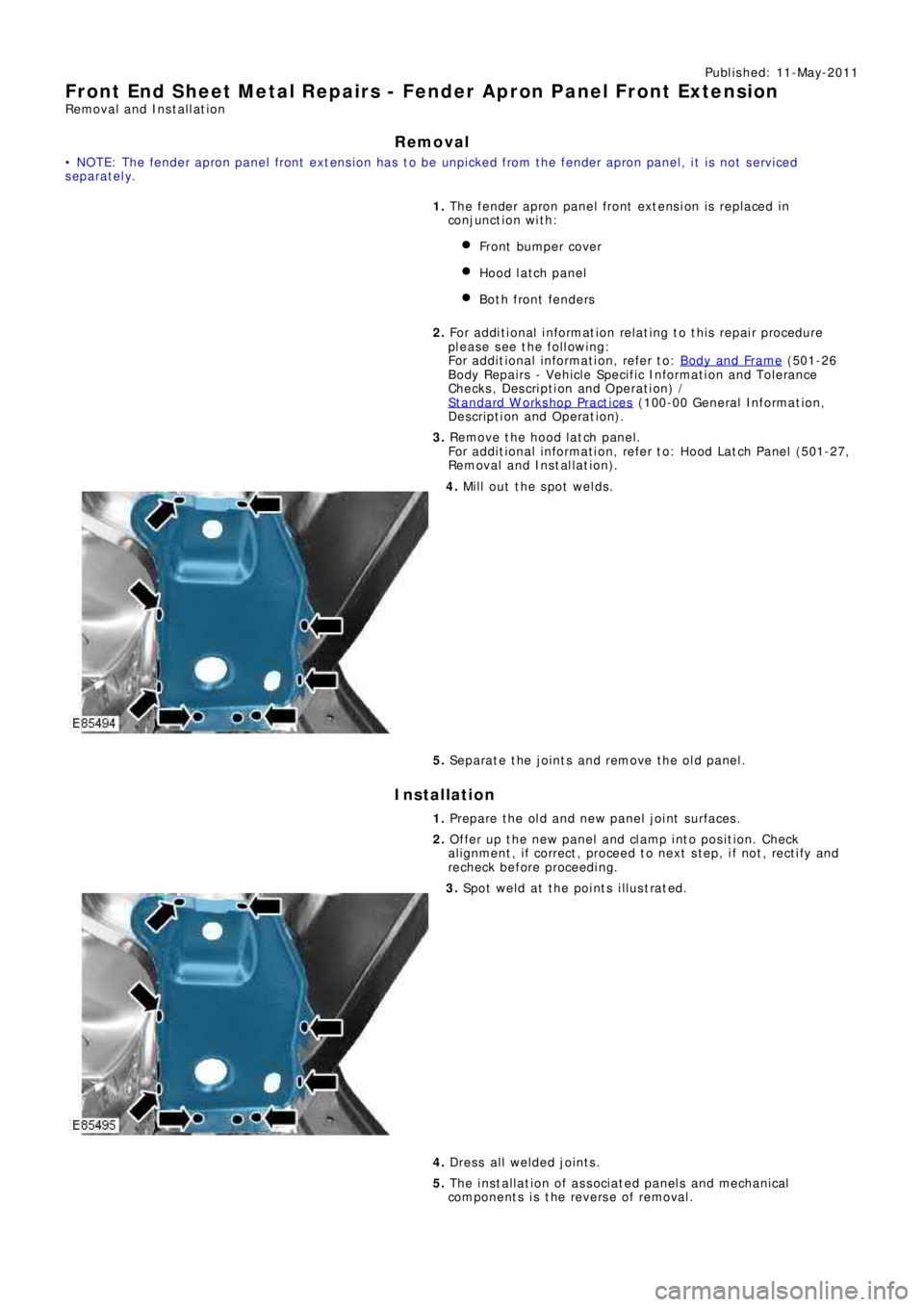
4. Mill out the spot welds.
5. Separate the joints and remove the old panel.
Installation
1. Prepare the old and new panel joint surfaces.
2. Offer up the new panel and clamp into position. Check
al ignment , i f correct , proceed t o next s t ep, i f not , rect i fy and
recheck before proceeding.
3. Spot weld at the points illustrated.
4. Dress all welded joints.
5. The installation of associated panels and mechanical
components is the reverse of removal.
Page 2568 of 3229
Publ is hed: 11-May-2011
Front End Sheet Metal Repairs - Fender Apron Lower Panel
Removal and Installation
Removal
• NOTE: The fender apron lower panel is to be removed from the fender apron panel service panel; it is not available
separately.
• NOTE: The panel is serviced less its weld studs
1. T he f e nd e r a p ro n l o we r p a ne l i s re p l a ce d i n co nj unct i o n w i t h:
Front bumper cover
Hood lat ch panel
Both front fenders
2. Fo r a d d i t i o na l i nf o rma t i o n re l a t i ng t o t hi s re p a i r p ro ce d ure
please see the following:
Fo r a d d i t i o na l i nf o rma t i o n, re f e r t o : Body and Frame
(501-26
Body Repairs - Vehicle Specific Information and Tolerance
Checks, Description and Operation) /
St a nd a rd W o rks ho p P ra ct i ce s
(100-00 Ge ne ra l I nf o rma t i o n,
Description and Operation).
3. Remove t he hood l at ch panel.
Fo r a d d i t i o na l i nf o rma t i o n, re f e r t o : H o o d L a t ch P a ne l (501-27,
Removal and Installation).
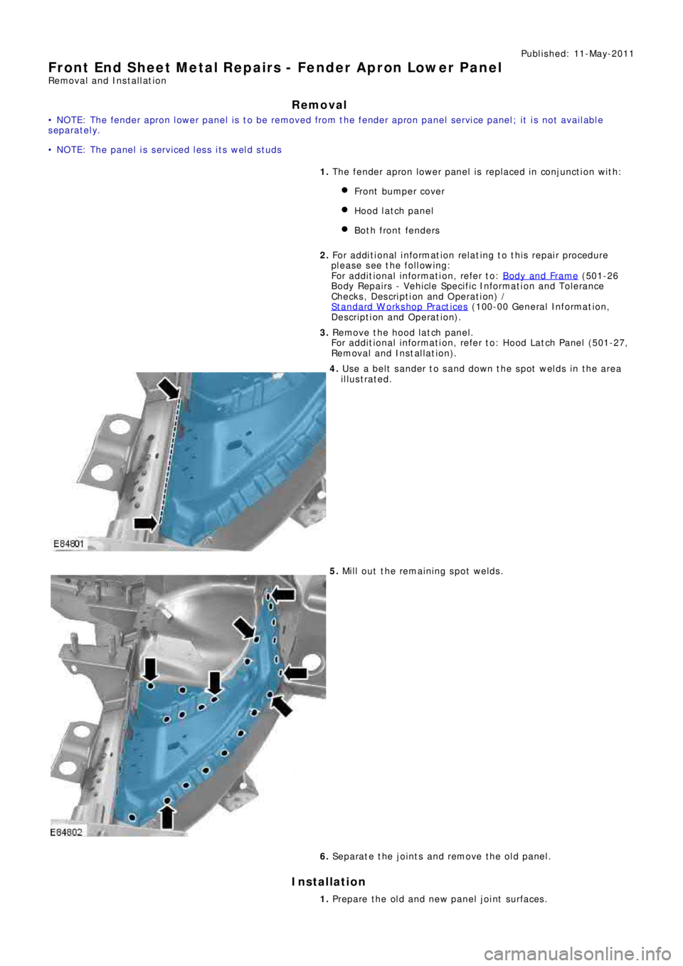
4. Use a belt sander to sand down the spot welds in the area
illustrated.
5. Mill out the remaining spot welds.
6. Separate the joints and remove the old panel.
Installation
1. Prepare the old and new panel joint surfaces.
Page 2570 of 3229
Publ is hed: 11-May-2011
Front End Sheet Metal Repairs - Fender Apron Upper Panel
Removal and Installation
Removal
• NOTE: The fender apron upper panel is s erviced as a s eparat e weld-on panel.
• NOTE: The service panel is not fully welded.
• NOTE: There is an NVH element attached inside this panel, it is not serviced on the new panel. Therefore, if damaged, a
new element will be required.
1. The fender apron upper panel is replaced in conjunct ion wit h:
Front bumper cover
Hood
Hood lat ch panel
Both front fenders
2. Fo r a d d i t i o na l i nf o rma t i o n re l a t i ng t o t hi s re p a i r p ro ce d ure
please see the following:
Fo r a d d i t i o na l i nf o rma t i o n, re f e r t o : Body and Frame
(501-26
Body Repairs - Vehicle Specific Information and Tolerance
Checks, Description and Operation) /
St a nd a rd W o rks ho p P ra ct i ce s
(100-00 Ge ne ra l I nf o rma t i o n,
Description and Operation).
3. Remove t he hood l at ch panel.
Fo r a d d i t i o na l i nf o rma t i o n, re f e r t o : H o o d L a t ch P a ne l (501-27,
Removal and Installation).
4. Remove the hood.
5. Remove the plenum chamber panel.
Fo r a d d i t i o na l i nf o rma t i o n, re f e r t o : Plenum Chamber
(412-01
Climate Control, Removal and Installation).
6. LH Side: Remove the air intake pipe.
7. RH Side: Release and lay aside the wiring harness.
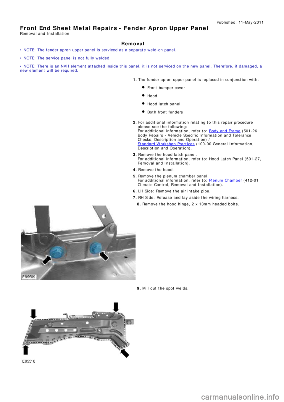
8. Remove t he hood hi nge, 2 x 13mm headed bol t s .
9. Mill out the spot welds.