2006 LAND ROVER FRELANDER 2 service
[x] Cancel search: servicePage 516 of 3229

wheel i s read by the opt ical-di git al s ens ors t o produce s teeri ng wheel rotat ional speed s ignals . The s teering angle s ens oris abl e t o meas ure a rot at ion range of +/- 720 degrees , alt hough t he s teering mechani s m wi ll only al low the s t eeringwheel t o rotat e a maxi mum of +/-540 degrees .
Signals from t he st eeri ng angl e s ens or are trans mi tt ed on t he vehicle hi gh s peed CAN bus , and received and proces sed byother s yst ems s uch as DSC. The trans mi tt ed i nformat ion i ncl udes det ails of st eering wheel angle and s t eering wheelrot ati onal s peed, along wit h s ignal i ntegri ty informati on.
If a fault occurs wi thi n t he st eeri ng angl e s ens or, a DTC wi ll be s et and s tored in t he s teering angle s ens or memory. Thes teeri ng angle s ensor faul t is al s o s tored in the ABS modul e memory that i lluminates t he appropri at e warning i ndi cat orlamps , depending on the sys tem functi ons affect ed (DSC/ETC, ABS, EBA/EBD, HDC). A warni ng chi me i s als o s ounded t oalert the driver to the fault condi ti on.
For vehicles ins tall ed wit h a high-l ine i ns t rument clus ter, a mes s age is di spl ayed in t he mes sage center, onl y if t he faul taffect s t he HDC funct ion.
For addit ional informat ion, refer t o:
Ins trument Clus ter (413-01 Ins t rument Clus t er, Descripti on and Operat ion),Informat ion and Mes s age Cent er (413-08 Informati on and Mes sage Cent er, Descripti on and Operat ion).
The s teeri ng angle s ensor and ABS modul e are abl e t o be i nt errogat ed us ing t he Land Rover approved diagnos t icequi pment.
Clockspring
The clocks pri ng is a rot ary coupling that provides t he electrical connect ion bet ween the fixed s t eering wheel module, andt he st eeri ng wheel mount ed cont rols and Supplement al Res t raint Sys tem (SRS) dri ver's ai rbag.
A colored indicator i s provided wi thi n the cl ocks pring and is vis i bl e t hrough a t rans parent pers pex cover when the s t eeringwheel i s removed, and t he st eeri ng angl e s ens or is aligned t o t he cent ral posi ti on. The indicator makes s ure t he s teeringangl e s ensor and s t eering s ys tem are correct ly al igned fol lowi ng repairs t o the st eeri ng mechanis m.
Service Information
Before s eparat ing the s t eering component s from the connect ing s t eering column, t he clocks pri ng mus t be ali gned to thecent er pos i ti on (i ndi cat or vi s ible) and t he wheels point ing s t raight ahead. The clockspring i s ret ained i n the cent ralposi ti on wit h a locki ng s crew.
INSTRUMENT CLUSTER INDICATOR LAMPS
Page 520 of 3229
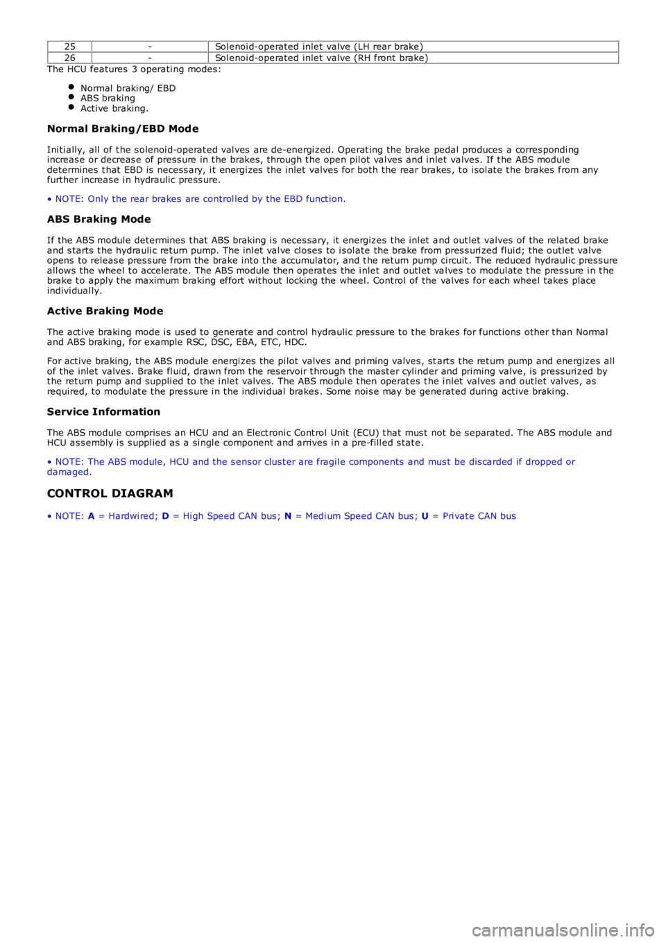
25-Sol enoi d-operated inlet valve (LH rear brake)
26-Sol enoi d-operated inlet valve (RH front brake)
The HCU features 3 operati ng modes:
Normal braki ng/ EBDABS brakingActi ve braking.
Normal Braking/EBD Mod e
Ini ti ally, all of t he s olenoi d-operat ed val ves are de-energi zed. Operat ing the brake pedal produces a corres pondi ngincreas e or decreas e of press ure in t he brakes , through t he open pil ot val ves and i nlet valves. If t he ABS moduledetermines t hat EBD is necess ary, i t energi zes the i nlet valves for both the rear brakes , t o i sol at e t he brakes from anyfurther increas e i n hydraulic press ure.
• NOTE: Only the rear brakes are control led by the EBD funct ion.
ABS Braking Mode
If the ABS modul e determines t hat ABS braking i s neces sary, it energizes t he inl et and out let valves of the relat ed brakeand s tarts t he hydrauli c ret urn pump. The i nl et val ve cl oses to i s ol ate the brake from pres s uri zed flui d; the out let valveopens to releas e pres s ure from the brake int o t he accumulat or, and t he ret urn pump ci rcuit . The reduced hydraul ic pres s ureall ows the wheel t o accelerate. The ABS module then operat es the i nlet and outl et val ves t o modul at e t he pres s ure i n t hebrake t o apply t he maximum braking effort wit hout locki ng the wheel . Cont rol of the val ves for each wheel takes placeindivi dual ly.
Active Braking Mode
The act ive braki ng mode i s us ed to generat e and control hydrauli c pres s ure t o t he brakes for funct ions other t han Normaland ABS braking, for example RSC, DSC, EBA, ETC, HDC.
For act ive braking, t he ABS module energi zes the pi lot valves and pri ming valves , start s t he ret urn pump and energizes allof the inlet valves. Brake fl uid, drawn from t he res ervoir t hrough the mast er cyl inder and priming valve, is press uri zed byt he ret urn pump and suppli ed to the i nlet valves. The ABS modul e t hen operat es t he inl et valves and out let val ves , asrequired, to modul at e t he pres s ure i n t he indivi dual brakes . Some noi s e may be generat ed during act ive braki ng.
Service Information
The ABS module compris es an HCU and an Elect roni c Cont rol Unit (ECU) t hat mus t not be s eparated. The ABS module andHCU as s embly i s s uppl ied as a si ngl e component and arrives i n a pre-fill ed s tat e.
• NOTE: The ABS module, HCU and the s ens or clus t er are fragil e components and mus t be dis carded if dropped ordamaged.
CONTROL DIAGRAM
• NOTE: A = Hardwi red; D = Hi gh Speed CAN bus ; N = Medi um Speed CAN bus ; U = Pri vat e CAN bus
Page 603 of 3229
Publi s hed: 23-Aug-2011
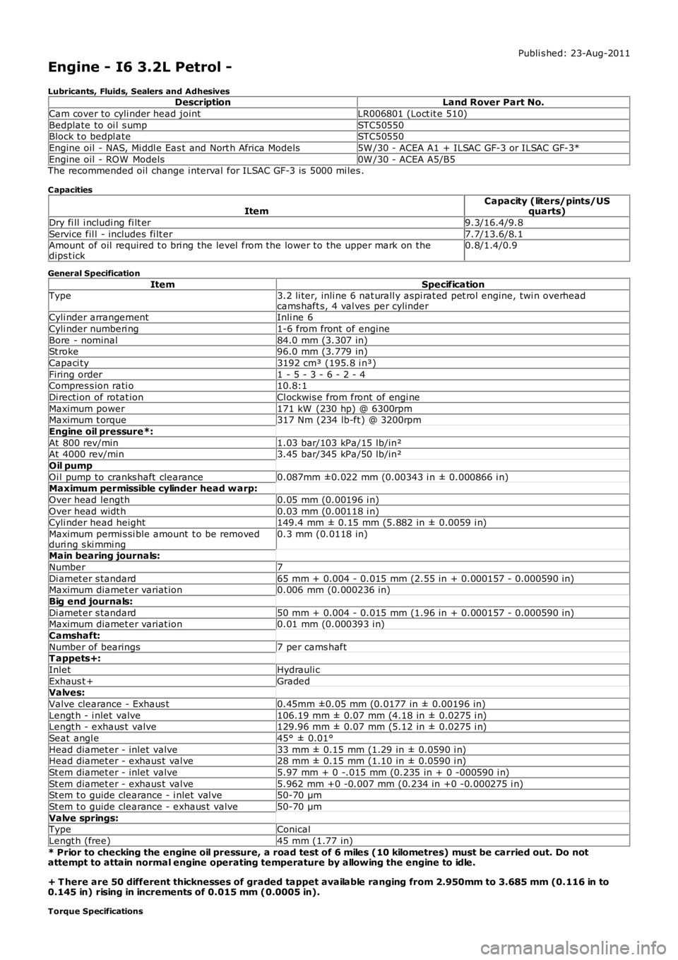
Engine - I6 3.2L Petrol -
Lubricants, Fluids, Sealers and AdhesivesDescriptionLand Rover Part No.
Cam cover to cyli nder head jointLR006801 (Loct it e 510)
Bedplate to oi l s umpSTC50550Block t o bedpl ateSTC50550
Engine oil - NAS, Mi ddl e Eas t and Nort h Africa Models5W /30 - ACEA A1 + ILSAC GF-3 or ILSAC GF-3*
Engine oil - ROW Models0W /30 - ACEA A5/B5The recommended oil change i nterval for ILSAC GF-3 is 5000 mi les .
C apacities
ItemCapacity (liters/pints/USquarts)
Dry fi ll i ncludi ng fi lt er9.3/16.4/9.8
Service fil l - includes fi lt er7.7/13.6/8.1Amount of oil required t o bri ng the level from the lower to the upper mark on thedips t ick0.8/1.4/0.9
General Specification
ItemSpecificationType3.2 li ter, inli ne 6 nat urall y aspi rat ed pet rol engine, twi n overheadcams haft s, 4 val ves per cylinderCyli nder arrangementInli ne 6
Cyli nder numberi ng1-6 from front of engine
Bore - nominal84.0 mm (3.307 in)St roke96.0 mm (3.779 in)
Capaci ty3192 cm³ (195.8 i n³)
Firing order1 - 5 - 3 - 6 - 2 - 4Compres s ion rati o10.8:1
Di recti on of rotat ionCl ockwis e from front of engi ne
Maximum power171 kW (230 hp) @ 6300rpmMaximum t orque317 Nm (234 lb-ft ) @ 3200rpm
Engine oil pressure*:
At 800 rev/min1.03 bar/103 kPa/15 lb/in²At 4000 rev/min3.45 bar/345 kPa/50 lb/in²
Oil pump
Oi l pump to cranks haft clearance0.087mm ±0.022 mm (0.00343 i n ± 0.000866 i n)Maximum permissible cylinder head w arp:
Over head length0.05 mm (0.00196 i n)
Over head widt h0.03 mm (0.00118 i n)Cyli nder head height149.4 mm ± 0.15 mm (5.882 in ± 0.0059 i n)
Maximum permi s si ble amount t o be removedduri ng s ki mmi ng0.3 mm (0.0118 in)
Main bearing journals:
Number7
Di amet er s tandard65 mm + 0.004 - 0.015 mm (2.55 in + 0.000157 - 0.000590 in)Maximum diamet er variat ion0.006 mm (0.000236 in)
Big end journals:
Di amet er s tandard50 mm + 0.004 - 0.015 mm (1.96 in + 0.000157 - 0.000590 in)Maximum diamet er variat ion0.01 mm (0.000393 i n)
Camshaft:
Number of bearings7 per cams haftT appets+:
InletHydrauli c
Exhaus t +GradedValves:
Valve clearance - Exhaus t0.45mm ±0.05 mm (0.0177 in ± 0.00196 in)
Lengt h - i nlet valve106.19 mm ± 0.07 mm (4.18 in ± 0.0275 i n)Lengt h - exhaus t valve129.96 mm ± 0.07 mm (5.12 in ± 0.0275 i n)
Seat angl e45° ± 0.01°
Head diamet er - inlet valve33 mm ± 0.15 mm (1.29 in ± 0.0590 i n)Head diamet er - exhaus t val ve28 mm ± 0.15 mm (1.10 in ± 0.0590 i n)
St em diamet er - inlet valve5.97 mm + 0 -.015 mm (0.235 in + 0 -000590 i n)
St em diamet er - exhaus t val ve5.962 mm +0 -0.007 mm (0.234 in +0 -0.000275 i n)St em t o guide clearance - i nlet val ve50-70 µm
St em t o guide clearance - exhaus t valve50-70 µm
Valve springs:TypeConical
Lengt h (free)45 mm (1.77 in)
* Prior to checking the engine oil pressure, a road test of 6 miles (10 kilometres) must be carried out. Do notattempt to attain normal engine operating temperature by allowing the engine to idle.
+ T here are 50 different thicknesses of graded tappet available ranging from 2.950mm to 3.685 mm (0.116 in to0.145 in) rising in increments of 0.015 mm (0.0005 in).
Torque Specifications
Page 752 of 3229
Publi s hed: 11-May-2011
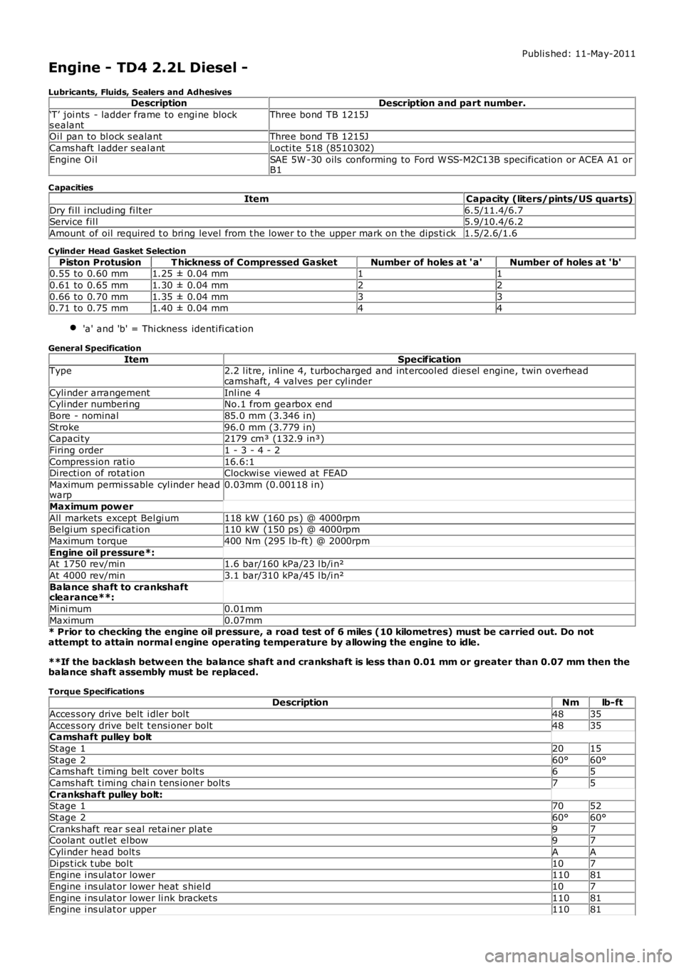
Engine - TD4 2.2L Diesel -
Lubricants, Fluids, Sealers and AdhesivesDescriptionDescription and part number.
‘T’ joi nts - ladder frame to engi ne blocks ealantThree bond TB 1215J
Oi l pan to bl ock s ealantThree bond TB 1215J
Cams haft l adder s eal antLocti te 518 (8510302)
Engine Oi lSAE 5W -30 oils conforming to Ford W SS-M2C13B specificat ion or ACEA A1 orB1
C apacities
ItemCapacity (liters/pints/US quarts)
Dry fi ll i ncludi ng fi lt er6.5/11.4/6.7Service fil l5.9/10.4/6.2
Amount of oil required t o bri ng level from t he lower t o t he upper mark on t he dips tick1.5/2.6/1.6
C ylinder Head Gasket Selection
Piston ProtusionT hickness of Compressed GasketNumber of holes at ' a'Number of holes at 'b'0.55 to 0.60 mm1.25 ± 0.04 mm11
0.61 to 0.65 mm1.30 ± 0.04 mm22
0.66 to 0.70 mm1.35 ± 0.04 mm330.71 to 0.75 mm1.40 ± 0.04 mm44
'a' and 'b' = Thi ckness identi fi cat ion
General Specification
ItemSpecificationType2.2 l it re, i nl ine 4, t urbocharged and int ercool ed dies el engine, t win overheadcamshaft , 4 valves per cyl inder
Cyli nder arrangementInl ine 4Cyli nder numberi ngNo.1 from gearbox end
Bore - nominal85.0 mm (3.346 i n)
St roke96.0 mm (3.779 i n)Capaci ty2179 cm³ (132.9 in³)
Firing order1 - 3 - 4 - 2
Compres s ion rati o16.6:1Di recti on of rotat ionClockwi s e viewed at FEAD
Maximum permi s sable cyl inder headwarp0.03mm (0.00118 i n)
Maximum pow er
All markets except Bel gi um118 kW (160 ps ) @ 4000rpmBelgi um s peci fi cat ion110 kW (150 ps ) @ 4000rpm
Maximum t orque400 Nm (295 l b-ft ) @ 2000rpm
Engine oil pressure*:At 1750 rev/min1.6 bar/160 kPa/23 l b/i n²
At 4000 rev/min3.1 bar/310 kPa/45 l b/i n²
Balance shaft to crankshaftclearance**:
Mi ni mum0.01mm
Maximum0.07mm* Prior to checking the engine oil pressure, a road test of 6 miles (10 kilometres) must be carried out. Do notattempt to attain normal engine operating temperature by allowing the engine to idle.
**If the backlash betw een the balance shaft and crankshaft is less than 0.01 mm or greater than 0.07 mm then thebalance shaft assembly must be replaced.
Torque SpecificationsDescriptionNmlb-ft
Acces s ory drive belt i dler bol t4835
Acces s ory drive belt t ensi oner bolt4835Camshaft pulley bolt
St age 12015
St age 260°60°Cams haft t imi ng belt cover bolt s65
Cams haft t imi ng chai n t ens ioner bolt s75
Crankshaft pulley bolt:St age 17052
St age 260°60°
Cranks haft rear s eal retai ner pl at e97Coolant outl et el bow97
Cyli nder head bolt sAA
Di ps t ick t ube bol t107Engine i ns ulat or lower11081
Engine i ns ulat or lower heat s hiel d107
Engine i ns ulat or lower li nk bracket s11081Engine i ns ulat or upper11081
Page 774 of 3229
For furt her det ail s on connecti ng rod bi g-end beari ng ins tal lati on, refer t o t he relevant Service Repair Procedures (SRP).
The pis t ons are manufactured from al uminum alloy and are i ns t alled wit h 2 compres s ion rings , and an oil cont rol ring wi tha s piral spring. A s teel ins ert i s i ns t alled in t he pis t on upper ring groove t o provi de reinforcement. The pis t on crown i s at oroidal des i gn that forms a pronounced bowl in t he center of the pi s ton head. Recesses are als o formed in t he pis t oncrown t o provi de cl earance for t he 4 valve heads. This des ign of combus ti on chamber promot es high l evel s of swirl andt urbulence required for complete combus t ion of t he air/fuel mi xture, and al so improves t he engine emi ss i ons .
The 3 pi st on rings mus t be ins t al led wi th the ring gaps s paced at 120° (wit h permis sible tolerance of 15° t o 20°) to eachother, around the pi st on. The 2 upper compres s ion rings are s tamped wi th 't op' t o aid ins tall ati on. The gap of t he doubl ebevel ed oil cont rol ring mus t als o be oppos it e t he s pi ral s pri ng joint .
The ful l ski rt pis t on is coated wit h a graphi te bas ed s ubst ance to reduce fri cti on wit h t he cyl inder bore. The graphi te bas edcoat ing i s es pecial ly i mport ant during t he engine runni ng in period and s t art-up. The pis ton al so incorporat es 2 oil coolingchannels t hat are formed on the unders i de of the pi st on head.
Two bus hed hol es are formed at oppos it e s ides of t he pis ton s kirt for i nst all at ion of a full y floati ng gudgeon pin. Thegudgeon pi n pass es t hrough the pi s ton bus hed hol es and connecti ng rod s mal l-end, and i s ret ained at each end wit h acircl ip. The pis ton, gudgeon pi n and connecti ng rod smal l-end are s uppli ed wit h oil from an oil s pray jet, l ocat ed bel oweach cyli nder bore.
Duri ng ins tal lat ion of t he pis tons , the s t amped direct ion arrow and 'DIST' on each pis ton crown mus t face t oward t he frontof the engine (acces s ory drive end).
For furt her det ail s on pis t on and pis ton ring ins tall ati on, refer t o the relevant Service Repai r Procedures (SRP) manual.
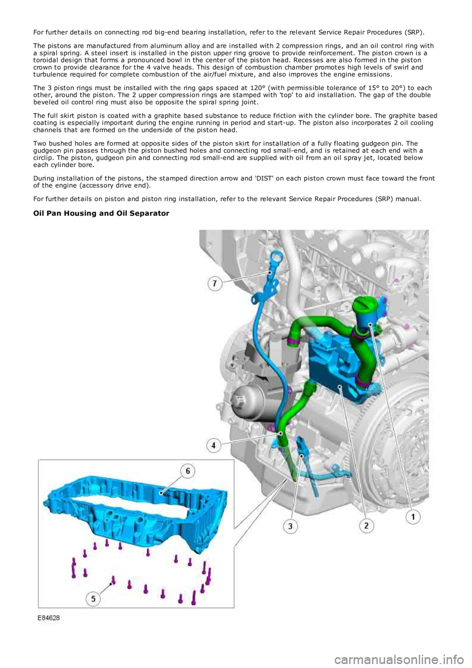
Oil Pan Housing and Oil Separator
Page 780 of 3229
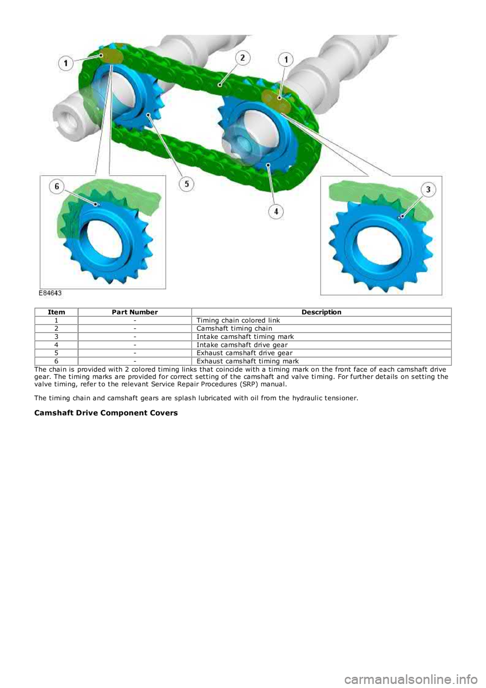
ItemPart NumberDescription
1-Timing chain colored li nk2-Cams haft t imi ng chai n
3-Intake cams haft ti ming mark
4-Intake cams haft dri ve gear5-Exhaus t cams haft dri ve gear
6-Exhaus t cams haft ti ming mark
The chai n is provided wi th 2 col ored t imi ng li nks that coinci de wi th a ti ming mark on the front face of each camshaft drivegear. The t imi ng marks are provided for correct s et t ing of t he cams haft and valve timing. For furt her det ails on s et t ing t hevalve t imi ng, refer t o t he relevant Service Repair Procedures (SRP) manual.
The t imi ng chai n and camshaft gears are spl as h l ubricat ed wit h oil from the hydraul ic t ens i oner.
Camshaft Drive Component Covers
Page 785 of 3229
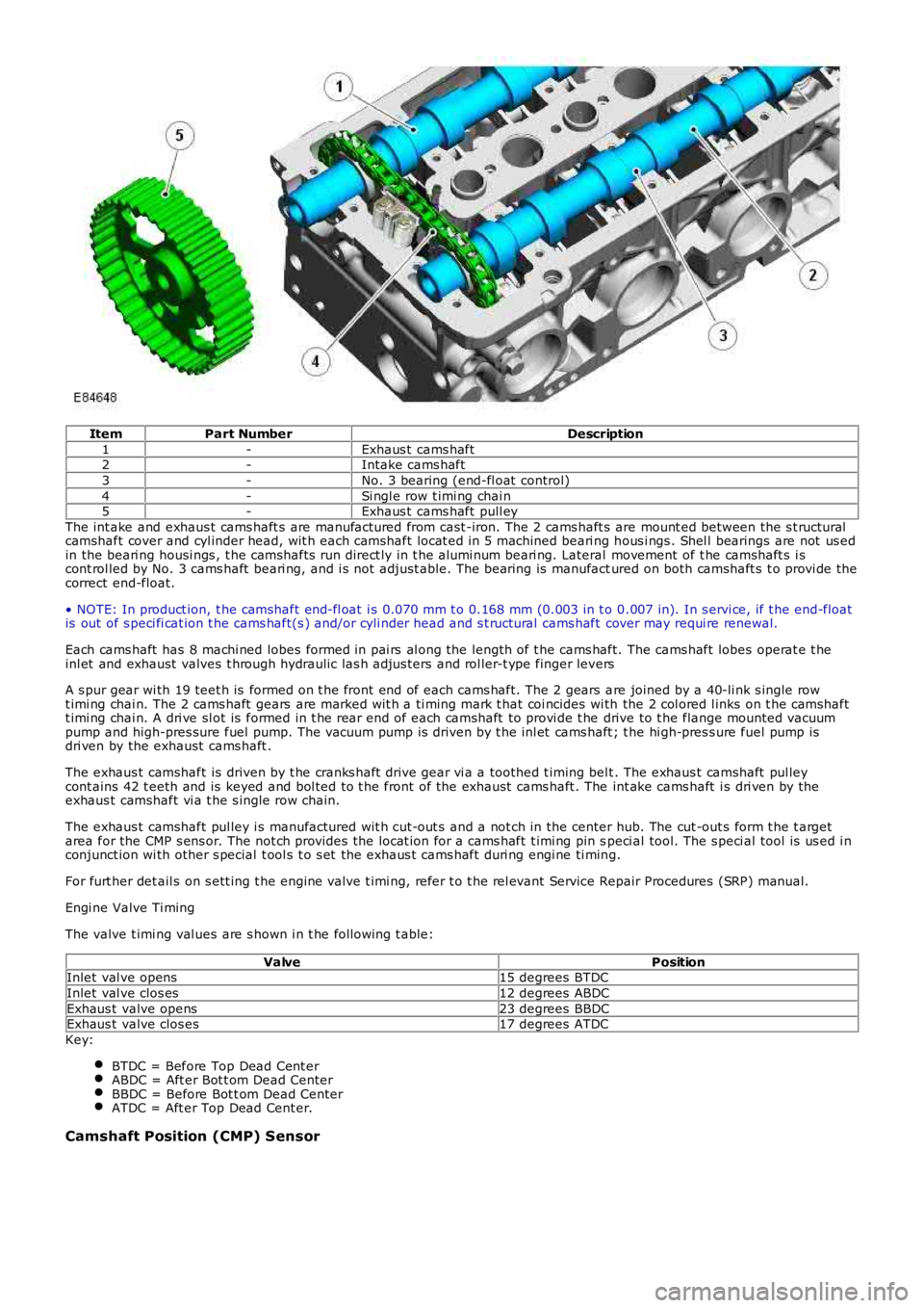
ItemPart NumberDescription
1-Exhaus t cams haft2-Intake cams haft
3-No. 3 bearing (end-fl oat control)
4-Si ngl e row t imi ng chai n5-Exhaus t cams haft pull ey
The int ake and exhaus t cams haft s are manufactured from cast -iron. The 2 cams haft s are mount ed between the s t ructuralcamshaft cover and cyl inder head, wit h each camshaft locat ed i n 5 machined beari ng hous i ngs . Shel l bearings are not us edin the beari ng housi ngs , t he camshafts run direct ly in t he alumi num beari ng. Lateral movement of t he camshaft s i scont rol led by No. 3 cams haft beari ng, and i s not adjust able. The bearing is manufactured on both camshaft s t o provi de thecorrect end-float.
• NOTE: In product ion, t he camshaft end-fl oat i s 0.070 mm t o 0.168 mm (0.003 in t o 0.007 in). In s ervi ce, if t he end-floatis out of s peci fi cat ion t he cams haft(s ) and/or cyli nder head and s t ructural cams haft cover may requi re renewal.
Each cams haft has 8 machi ned lobes formed in pai rs al ong the length of t he cams haft. The cams haft lobes operat e t heinl et and exhaust valves t hrough hydraulic las h adjus ters and rol ler-t ype finger levers
A s pur gear wi th 19 teet h is formed on t he front end of each cams haft. The 2 gears are joined by a 40-li nk s ingle rowt imi ng chai n. The 2 cams haft gears are marked wit h a ti ming mark t hat coi ncides wi th the 2 col ored l inks on t he camshaftt imi ng chai n. A dri ve sl ot is formed in t he rear end of each camshaft to provi de t he drive to t he flange mounted vacuumpump and high-pres sure fuel pump. The vacuum pump is driven by t he inl et cams haft ; the hi gh-pres s ure fuel pump isdri ven by the exhaust cams haft .
The exhaus t camshaft is driven by t he cranks haft drive gear vi a a toothed t iming belt . The exhaus t camshaft pul leycont ains 42 t eeth and is keyed and bol ted to t he front of the exhaust cams haft . The int ake cams haft i s dri ven by theexhaus t camshaft vi a t he s ingle row chain.
The exhaus t camshaft pul ley i s manufactured wit h cut-out s and a not ch in the center hub. The cut -out s form t he t argetarea for the CMP s ens or. The not ch provides the locat ion for a cams haft t imi ng pin speci al tool. The s peci al tool is us ed i nconjunct ion wi th other s pecial t ool s t o s et the exhaus t cams haft duri ng engi ne ti ming.
For furt her det ail s on s ett ing t he engine valve t imi ng, refer t o t he rel evant Service Repair Procedures (SRP) manual.
Engi ne Valve Ti ming
The valve t imi ng val ues are s hown i n t he fol lowing t able:
ValvePositionInlet val ve opens15 degrees BTDC
Inlet val ve clos es12 degrees ABDC
Exhaus t valve opens23 degrees BBDCExhaus t valve clos es17 degrees ATDC
Key:
BTDC = Before Top Dead Cent erABDC = Aft er Bot t om Dead CenterBBDC = Before Bot t om Dead CenterATDC = Aft er Top Dead Cent er.
Camshaft Position (CMP) Sensor
Page 862 of 3229
Publi s hed: 11-May-2011
Engine - TD4 2.2L Diesel - Cylinder Head
Removal and Inst all ati on
Removal
• NOTE: The valve cover and cylinder head is machined as an ass embly and cannot be serviced s eparately.
Remove t he cover and dis connect the bat tery ground cabl e.
Refer t o: Specificati ons (414-00 Bat tery and Charging Sys tem -General Informat ion, Specificati ons).
1.
2. W ARNING: Make sure t o s upport the vehicle wit h axles tands .
Rais e and s upport t he vehi cl e.
2.
Remove t he exhaus t manifol d.
Refer t o: Exhaus t Mani fol d (303-01B Engi ne - TD4 2.2L Di esel ,Removal and Ins tall ati on).
3.
Remove t he camshaft s .
Refer t o: Camshafts (303-01B Engine - TD4 2.2L Dies el, Removaland Inst all at ion).
4.
Remove t he thermost at.
Refer t o: Thermos tat (303-03B Engi ne Cool ing - TD4 2.2L Di es el,Removal and Ins tall ati on).
5.
Remove t he RH engine mount .
Refer t o: Engi ne Mount RH (303-01B Engi ne - TD4 2.2L Di esel ,Removal and Ins tall ati on).
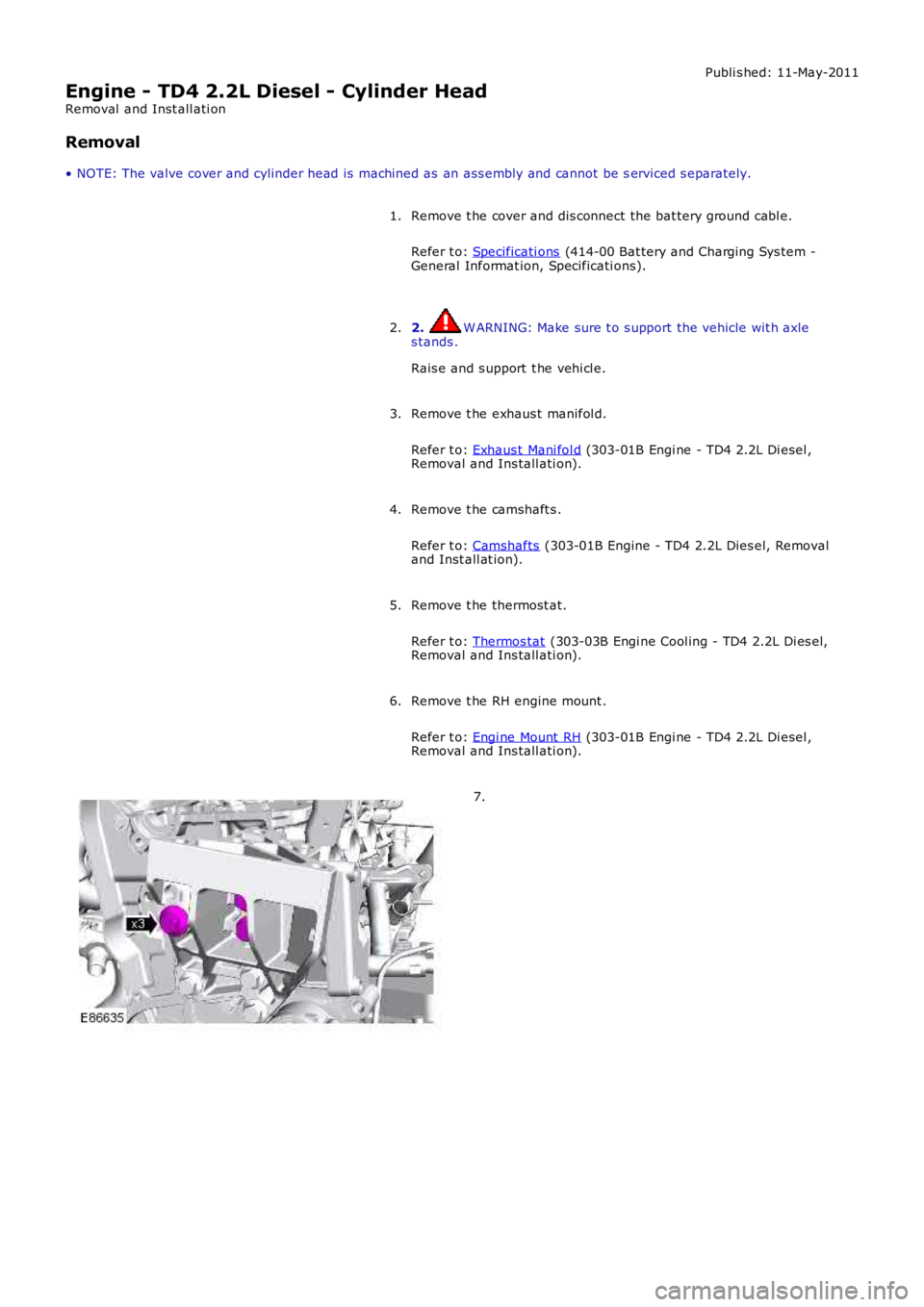
6.
7.