2006 LAND ROVER FRELANDER 2 service
[x] Cancel search: servicePage 1817 of 3229
cus t omer.
• NOTE: The t erm `New Vehicle' refers t o a vehicle at any part of the deli very proces s from l eavi ng the factory to arri vingat a port of ent ry, deal ers hip, ret ailer, including any s t orage facil it ies en route or a vehi cl e being s t ored pri or to sal e atdeal ers hip / ret ai ler.
• NOTE: Mi dt roni cs 393, 394. 493 and 494 t es ters mus t not be us ed t o t est AGM batt eri es as thes e t est ers are not capableof correctl y t es t ing AGM batt eries and can gi ve an incorrect resul t. For AGM batt ery tes ti ng us e the EXP1080 t es t er or t heGR1 Di agnos ti cs charger.
NEW VEHICLES
A Mi dtroni cs tes t er s hould be us ed t o as s es s t he condi ti on of the bat tery for new vehicles . The t es t resul ts s hould berecorded on t he St orage His t ory Sheet (s ee Vehicle St orage manual).
Scenario 1 - Dealership / Retailer (Responsibility: Dealer / Retailer)
1. W i thin 24 hours of arrival at the dealer / retail er proceed as foll ows:
Perform a Mi dt roni cs bat tery tes t (See Appendix A.)Carry out the recommended act ions accordi ngl y.
2. If t he Mi dt roni cs res ul t is "Good Bat tery" t he vehi cle may be s tored.
For al l new vehi cl es in st orage t he t rans it rel ay MUST be fit ted, or t he Transi t Mode enabl ed where us ed. Forvehi cl es wit hout a t ransi t rel ay or a Trans it Mode, the bat tery negat ive cable MUST BE DISCONNECTED from thebatt ery.
3. The bat t ery mus t be t est ed and/or re-charged every mont h and MUST be re-charged aft er every t hree mont h period.
4. Record your t est res ul ts on the St orage Hi s tory Sheet (see Vehi cl e Storage Manual ) to indicate when a re-charge wil l beneces s ary.
Scenario 2 - Delivery to the Customer (Responsibility: Dealer / Retailer)
• NOTE: It is es s ent ial t hat t he followi ng act ions are conducted i n t he 24 hours prior to the agreed hand over t ime:
1. Perform a Midt ronics Bat tery tes t (See Appendix A).
2. Carry out the recommended acti ons accordingl y.
3. The vehi cl e s houl d only be releas ed to the cus tomer i f Midt ronics has t es t ed t he batt ery as "Good Batt ery"
Spare Part Batteries
Lead aci d batt eri es wil l, as a resul t of nat ural chemical proces s es , s lowl y s el f discharge thems elves over a peri od of ti me(even when open circui t and no electrical load applied).
In the cas e of s pare part s bat teri es, a Midt ronics t est er s hould be us ed to as s es s the condit ion of new s pare partsbatt eri es .
The batt eri es must be st ored such t hat t hey cannot get wet and are not i n direct s unli ght .
Any batt eri es which are dropped must be scrapped. Thi s applies even i f no ext ernal damage is apparent .
Scenario 1 - Spare Part Batteries Within Dealer Stock But Not Yet Fitted To A Vehicle (Responsibility:
Dealer / Retailer)
1. For a bat t ery i n the Deal er parts or i n ready t o us e s t ock but not yet fit t ed to a vehi cl e t he fol lowing rules must befol lowed:
Check t he batt ery condit ion on recei pt by performing a Midt ronics bat tery tes t (See Appendix A).Batt eri es should onl y be returned t o s t orage if t he Mi dtroni cs tes ter i ndi cat es "Good Bat tery".The batt ery condit ion s houl d be rechecked every 30 days by performing a Midt ronics batt ery tes t (See Appendix A).If required bat teries s hould be recharged as des cri bed in t he "Batt ery Chargi ng and Maint enance" s ecti on of thi smanual.
2. 2 All bat teries mus t be cont rol led vi a a FIFO (Fi rs t In First Out ) process to ens ure aged bat teries are not hel d and t hebatt eri es are not all owed to age unnecess ari ly.
VEHICLES IN SERVICE
The Midt ronics hand-held tes ter or t he Midt ronics Di agnos ti c Charger are t he preferred tools to as s es s bat t ery condi ti on forvehi cl es in service. The t es t res ult s s houl d be recorded on the In-Servi ce Bat t ery Report Form (See Appendix B).
Midtronics Testing - In-Service Testing Only
• NOTE: The batt ery s urface charge mus t be removed before t his t est i n accordance with the procedure in Appendi x A.Ensure t hat t he batt ery terminal connect ors are clean. W hen connecti ng t he Midt ronics t est ing equipment , connect the REDclip to the pos it ive (+) batt ery terminal fi rs t, and t hen connect the BLACK cl ip t o t he negat ive (-) bat tery t ermi nal . Rockt he cl ips backward and forward to ens ure a good connecti on to the bat tery.
1. Perform a Midt ronics bat tery tes t (See Appendix A).
2. Carry out the recommended acti ons accordingl y.
Page 1818 of 3229

6. BATTERY CHARGING AND MAINTENANCE
BATTERY CHARGING
It is es s ent ial t hat a sui tably vent ilat ed defi ned area exis ts in each dealers hip / ret ailer for bat tery charging. Li kewis e, anarea s hould be al lot ted for s crap batt eries , and clearl y indicat ed as s uch. It is recommended t hat dealers / ret ail ers al wayshave full y charged batt eri es ready for us e. However t he bat t ery MUST BE tes ted and charged i f neces sary every mont h, andcharged aft er three months i rres pecti ve of any t es t.
• CAUTIO NS:
Bat teri es mus t be re-charged aft er a maximum of 3 mont hs st orage (s ee Storage His tory s heet i n t he New VehicleStorage Manual ).
It is very important t hat when chargi ng bat t eries us ing the t racti on charger or ot her s t and-alone chargers t hat thecharger i s s et for t he correct t ype of bat tery before chargi ng commences . If t he wrong swi tch i s s elected t he res ult woul dbe a bat tery that i s not charged full y and / or overheat ing can occur. Fol low the manufact urers operat ing ins truct ions .
Do not charge AGM bat t eries wit h vol tages over 14.8 volt s as t hi s wi ll damage the bat tery.
To bri ng a s ervi ceable but di scharged batt ery back t o a full y charged condit ion proceed as follows :
Check and i f neces s ary t op-up t he batt ery el ect rolyt e level.Charge t he batt ery us ing the Mi dtroni cs Diagnos t ic Charger (USA) or Tract ion Charger (all other market s) foll owingt he manufact urers operati ng ins t ructi ons .
• NOTE: W hen us ing the Mi dtroni cs Diagnost ic Charger, aut omati c mode mus t always be us ed. Aft er chargi ng and anal ysi s,t he charger may di s pl ay ‘Top-Off Charging’, pres s STOP t o end. Do not s top chargi ng unt il t he current falls to 5A or les s,otherwis e t he batt ery wi ll not be ful ly charged.
POST-CHARGE TEST METHODS
New Batteries, Batteries in Storage and In-Service Batteries
The purpos e of thi s tes t is to ens ure that t he chargi ng process has full y charged the bat tery.
• NOTE: IT IS RECOMMENDED THAT THIS TEST IS CO NDUCTED AT LEAST 24 HOURS AFTER THE CHARGE CY CLE ISCOMPLETED.
Page 1821 of 3229
APPENDIX A BATTERY TEST PROCESS
It is recommended t hat this tes t is conduct ed at leas t 24 hours after t he vehi cl e engine has been run or t he batt erycharged to avoi d the need of s urface charge removal or i f thi s t ime cons traint is unaccept abl e due t o circums t ances , thenconduct the charge s t ri p removal process .
Part 1 - Surface Charge Removal
• NOTE: Before carryi ng out a batt ery t est you must ens ure t hat there is no bat t ery s urface charge present .
• NOTE: The batt ery may be t es t ed eit her on a bench or on t he vehicle.
In the cas e of on-vehicle tes ti ng, t he batt ery must be is olated from t he vehi cl e by removal of t he bat t ery negati ve(-) cable from the bat tery t ermi nal before t he measurement is t aken unl ess the vehicle has a transi t rel ay fi tt ed oris in t rans it mode.
A vehicle which has had it s batt ery charged or been dri ven in a 24 hour period before t he tes t , must have i ts s urfacecharge removed us ing one of t he fol lowi ng methods :
1. If 24 hours have pas s ed s ince the las t ti me t he engine was run or the bat tery charged, proceed t o `Part 2 - Bat teryTest '.
2. Turn on t he i gni ti on. Swi tch on t he headlamps on hi gh beam for a mini mum 3 minut es .
3. Swit ch off t he headl amps . For vehi cl es tes t ed aft er t he t rans it relay has been removed, di s connect t he batt ery byremoval of the negati ve (-) cabl e. Vehi cl es wit h a trans i t relay fit t ed or wit h a l ow current t rans port mode enabled do notneed to have t he batt ery di s connect ed.
4. W ait a maximum of 5 mi nut es before recordi ng tes t res ult s for any bat tery measurements .
Part 2 - Battery Test
• NOTE: The batt ery s urface charge mus t be removed before t his t est i n accordance with the procedure in Part 1 above.Ensure t hat t he batt ery terminal connect ors are clean. W hen connecti ng t he Midt ronics t est ing equipment , connect the REDclip to the pos it ive (+) batt ery terminal fi rs t, and t hen connect the BLACK cl ip t o t he negat ive (-) bat tery t ermi nal . Rockt he cl ips backward and forward to ens ure a good connecti on to the bat tery.
• NOTE: Mi dt roni cs 393, 394. 493 and 494 t es ters mus t not be us ed t o t est AGM batt eri es as thes e t est ers are not capableof correctl y t es t ing AGM batt eries and can gi ve an incorrect resul t. For AGM batt ery tes ti ng us e the EXP1080 t es t er or t heGR1 Di agnos ti cs charger.
CAUTION: DO NOT connect t he t es t er to any ot her ci rcuit or chas s is poi nt ot her than t he batt ery negati ve terminal.
1. Att ach the Midtronics tes t er t o t he batt ery.
2. Fol low the i nst ruct ions on t he tes t er t o t est the bat tery. Ens ure t he correct batt ery type and s ize i s s elect ed.
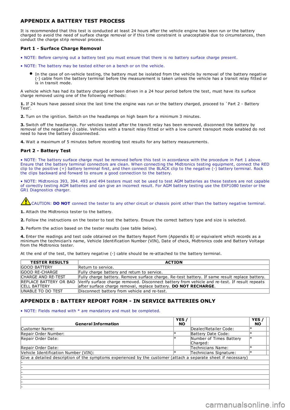
3. Perform the acti on based on the t es ter res ult s (s ee table bel ow).
4. Ent er the readings and t es t code obtained on the Bat tery Report Form (Appendi x B) or equi val ent whi ch records as ami ni mum the t echni ci an's name, Vehi cl e Ident ificati on Number (VIN), Dat e of check, Midtronics code and Bat t ery Volt agefrom the Mi dtroni cs tes ter.
At t he end of the t est , t he bat t ery negati ve (-) cabl e s houl d be re-att ached to t he batt ery terminal.
T EST ER RESULT SACT ION
GOOD BATTERYReturn t o s ervice.
GOOD RE-CHARGEFully charge bat tery and ret urn to servi ce.CHARGE AND RE-TESTFully charge bat tery. Remove s urface charge. Re-tes t batt ery. If s ame res ult repl ace bat tery.
REPLACE BATTERY OR BADCELL BATTERYVeri fy s urface charge removed. Dis connect bat tery from vehicle and re-tes t. If res ult repeat saft er surface charge removal , replace batt ery. DO NOT RECHARGE.
UNABLE TO DO TESTDis connect batt ery from vehi cl e and re-t es t .
APPENDIX B : BATTERY REPORT FORM - IN SERVICE BATTERIES ONLY
• NOTE: Fields marked wi th * are mandat ory and mus t be complet ed.
General InformationYES /NO YES /NO
Cus tomer Name: Dealer/Retai ler Code:*
Repair Order Number:*Batt ery Dat e Code:* Repair Order Dat e:*Number of Ti mes Bat teryCharged:*
Repair Order Dat e: Technici ans Name:*
Vehicle Identi fi cat ion Number (VIN):*Technici ans Si gnat ure:*
Gi ve a detail ed descripti on of the sympt oms experienced by the cus tomer (att ach a s eparate sheet if necess ary)-
-
--
-
-
Page 1868 of 3229
Publi s hed: 11-May-2011
Information and Entertainment System - Audio System
Des cript ion and Operat ion
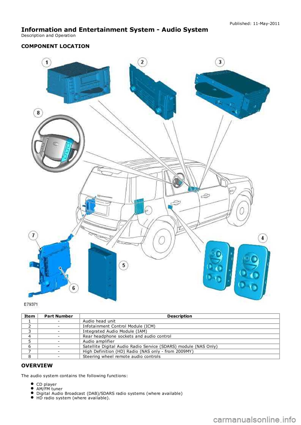
COMPONENT LOCATION
ItemPart NumberDescription1-Audio head unit
2-Infotai nment Cont rol Modul e (ICM)
3-Int egrat ed Audi o Module (IAM)4-Rear headphone socket s and audio control
5-Audio ampl ifier
6-Satell it e Di gi tal Audio Radi o Service (SDARS) modul e (NAS Only)7-High Defini ti on (HD) Radio (NAS onl y - from 2009MY )
8-Steering wheel remot e audi o control s
OVERVIEW
The audi o s yst em cont ai ns the foll owing funct ions :
CD pl ayerAM/FM tunerDigi tal Audio Broadcast (DAB)/SDARS radi o s yst ems (where avail abl e)HD radio s ys tem (where avai lable).
Page 1933 of 3229
• NOTE: Generic scan t ool s may not read the codes li st ed, or may read only 5-digi t codes . Match t he 5 digi ts from t he s cant ool t o t he fi rs t 5 di gi ts of the 7-digit code li s ted t o i dent ify the fault (the last 2 digi ts gi ve ext ra informati on read by themanufacturer-approved di agnos ti c s ys t em).
• NOTE: Check and recti fy bas ic faul ts before beginni ng diagnos t ic rout ines i nvol vi ng pinpoint t es t s.
• NOTE: Ins pect connect ors for s igns of water ingres s , and pins for damage and/or corros ion.
• NOTE: If DTCs are recorded and, aft er performi ng the pi npoi nt tes ts , a fault is not present , an int ermi tt ent concern maybe t he caus e. Always check for loose connect ions and corroded terminals .
• NOTE: Pri or to ins tall ati on/replacement of the Headlamp Ass embly carry out all relevant i nternal vis ual and mechanicalchecks for correct cable l ocat ion and t erminati on including: checks for corroded, bent or backed out pi ns or terminals ,incorrect ly i nserted connect ors and harnes s damage due t o chaffi ng or incorrect routing.
• NOTE: If the control modul e has been removed and rei nst all ed, carry out a DTC code clear, cycl e t he ignit ion st ate to off,t hen on. This will erase any DTCs that have been l ogged during t he module ins tall ation procedure
For a compl ete lis t of all Di agnos ti c Trouble Codes (DTCs) t hat could be logged on this vehicle, pleas e refer to Sect ion100-00.
REFER to: Di agnos ti c Trouble Code (DTC) Index - DTC: Headlamp Cont rol Modul e (HCM) (100-00 General Informati on,Des cript ion and Operat ion).
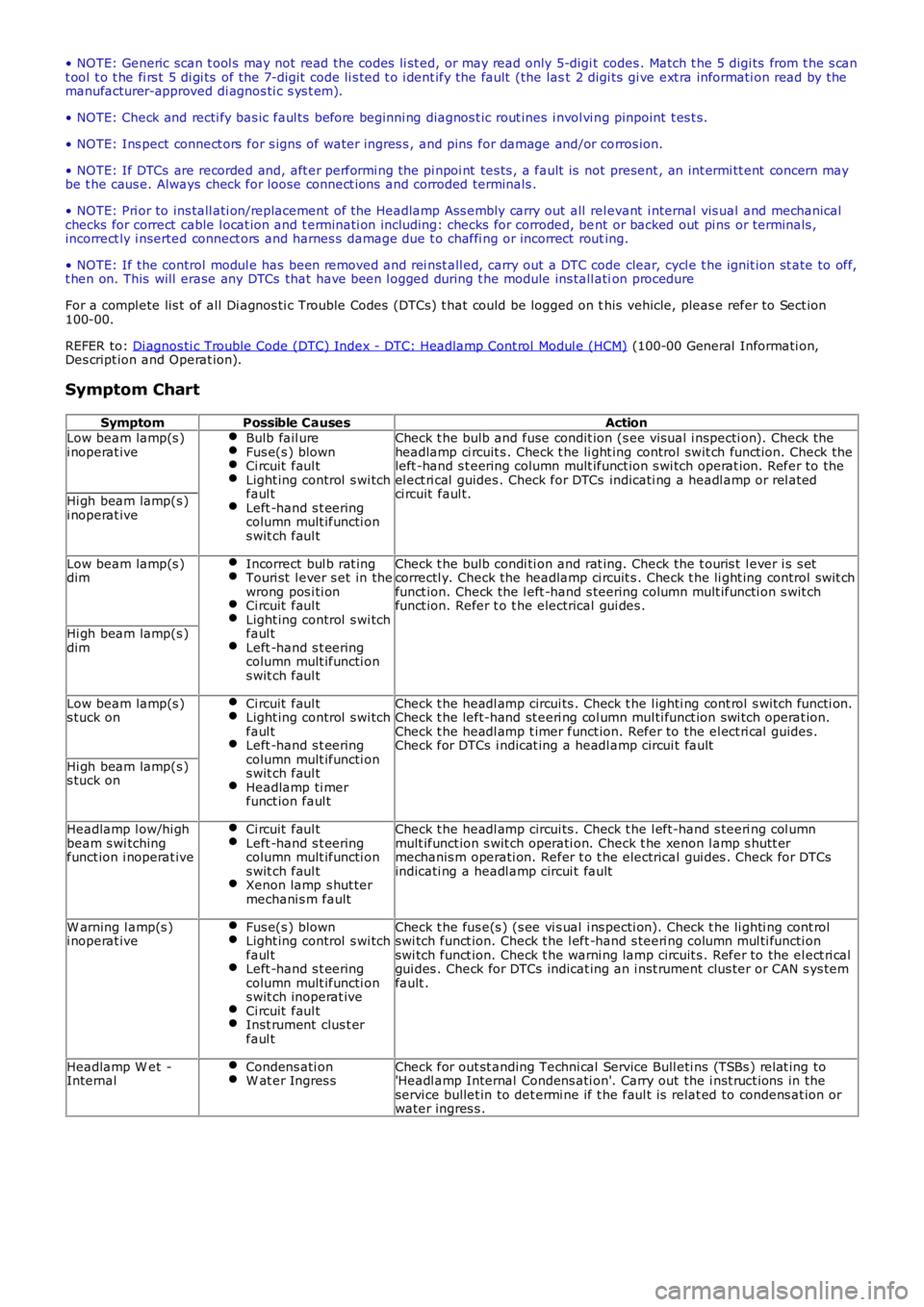
Symptom Chart
SymptomPossible CausesActionLow beam lamp(s )i noperat iveBulb fail ureFus e(s ) blownCi rcuit faul tLight ing control s wi tchfaul tLeft -hand s t eeringcolumn mult ifuncti ons wit ch faul t
Check t he bulb and fuse condit ion (s ee vis ual i nspecti on). Check theheadlamp ci rcuit s . Check t he li ght ing control swit ch funct ion. Check theleft -hand s t eering column mult ifunct ion s wi tch operat ion. Refer to theel ect ri cal guides . Check for DTCs indicati ng a headl amp or rel atedci rcuit faul t.Hi gh beam lamp(s )i noperat ive
Low beam lamp(s )dimIncorrect bul b rat ingTouri st l ever s et in thewrong pos i ti onCi rcuit faul tLight ing control s wi tchfaul tLeft -hand s t eeringcolumn mult ifuncti ons wit ch faul t
Check t he bulb condi ti on and rat ing. Check the t ouris t l ever i s s etcorrectl y. Check the headlamp ci rcuit s . Check t he li ght ing control swit chfunct ion. Check the l eft -hand s teering column mult ifuncti on s wit chfunct ion. Refer t o t he electrical gui des .
Hi gh beam lamp(s )dim
Low beam lamp(s )s tuck onCi rcuit faul tLight ing control s wi tchfaul tLeft -hand s t eeringcolumn mult ifuncti ons wit ch faul tHeadlamp ti merfunct ion faul t
Check t he headl amp circui ts . Check t he l ighti ng cont rol s wit ch functi on.Check t he left-hand st eeri ng col umn mul ti funct ion swi tch operat ion.Check t he headl amp t imer funct ion. Refer to the el ect ri cal guides .Check for DTCs i ndicat ing a headl amp circui t fault
Hi gh beam lamp(s )s tuck on
Headlamp l ow/hi ghbeam s wi tchingfunct ion i noperat ive
Ci rcuit faul tLeft -hand s t eeringcolumn mult ifuncti ons wit ch faul tXenon lamp s hut termechani s m fault
Check t he headl amp circui ts . Check t he l eft-hand s teeri ng col umnmult ifunct ion s wit ch operati on. Check t he xenon l amp s hutt ermechanis m operati on. Refer t o t he electrical gui des . Check for DTCsindicati ng a headl amp circui t fault
W arning l amp(s )i noperat iveFus e(s ) blownLight ing control s wi tchfaul tLeft -hand s t eeringcolumn mult ifuncti ons wit ch inoperat iveCi rcuit faul tInst rument clus t erfaul t
Check t he fus e(s ) (s ee vi s ual i ns pecti on). Check t he li ghti ng cont rolswi tch funct ion. Check t he l eft -hand s teeri ng column mul ti functi onswi tch funct ion. Check t he warni ng lamp circuit s . Refer to the el ect ri calgui des . Check for DTCs indicat ing an i nst rument clus ter or CAN s ys temfault .
Headlamp W et -InternalCondens ati onW at er Ingres sCheck for out st anding Techni cal Service Bull eti ns (TSBs ) rel at ing to'Headl amp Internal Condens ati on'. Carry out the i nst ruct ions in theservi ce bullet in to det ermi ne if t he faul t is relat ed to condens at ion orwater ingres s .
Page 2351 of 3229
12-BJB
PRINCIPLES OF OPERATION
The wiper and was her s ys tem can operate i n a number of different ways when t he vehi cle i s in power mode 4 through 8.Reques t s from t he RH st eering col umn mult i-functi on s wit ch are trans mi tt ed over t he LIN bus t o the CJB, which i s t he maincont rol ler for t he s ys t em.
Windshield Wiper Slow Wipe
On recei vi ng a reques t for s low winds hield wiper operati on the CJB will energi ze relay 11 in t he BJB. W hen energized, relay11 provides a feed t o t he s wit ch cont act s of rel ay 8, whi ch is al so located i n t he CJB. Relay 8 is t he fast /s l ow wi pe relay.W hen s l ow wipe has been reques t ed relay 8 remai ns de-energized, allowi ng a feed to fl ow acros s the relay s wi tch contactst o the winds hi eld wi per motor s low speed brus h contacts .
Windshield Wiper Fast Wipe
On recei vi ng a reques t for fast windshi el d wi per operat ion t he CJB wi ll energize relay 11 and relay 8 i n t he BJB. W henenergized, relay 11 provides a feed to the s wi tch contacts of relay 8. The energized rel ay 8 provi des a feed t o t hewinds hield wiper mot or fast speed brus h contacts .
Windshield Wiper Intermittent Wipe
On recei vi ng a reques t for i ntermit tent wi nds hield wiper operati on, t he CJB wi ll energize relay 11 i n t he BJB to operat e t hewipers at s low s peed. Software cont ained wi thin the CJB i nterprets the t ime delay reques ted and controls operat ion ofrel ay 11 accordi ngl y.
The int ermi tt ent wiper s et t ing broadcast on the LIN bus t o t he CJB equat es to the followi ng t ime del ays .
LIN Bus SignalT ime Delay (seconds)
122
215.539.5
46
53.561
In the event of a LIN bus fai lure bet ween t he CJB and the RH s teeri ng col umn mul ti -funct ion s wi tch, the CJB wi ll default to'Limp Home' mode (see bel ow).
Windshield Wiper Automatic Wipe
On recei vi ng a reques t for aut omat ic winds hi eld wi per operat ion, t he CJB int erpret s LIN bus mess ages received from therai n s ens or. The rain sens or provides LIN bus mess ages wit h values rangi ng from 0 to 7. A s ignal val ue of 0 is interpretedby t he CJB as there being no wat er on the windshi eld.
A s i gnal value from 1 t o 5 i s int erpret ed by t he CJB as there being a smal l amount of wat er hi tt ing the wi nds hiel d. In t hisins t ance, the CJB i nit iates a s low wipe rout ine as det ailed in t he 'W inds hield W iper Slow W i pe' s ect ion above.
A s i gnal value from 6 t o 7 i s int erpret ed by t he CJB as there being a large amount of water hi tt ing t he wi nds hield. In t hisins t ance, the CJB i nit iates a fas t wi pe routi ne as detai led i n t he 'W i ndshi el d W iper Fas t W i pe' s ecti on above.
Rain s ens or s ens it ivit y can be adjus ted by turni ng t he rot ary control on the RH st eeri ng col umn mul ti -funct ion s wit ch t ot he required pos i ti on. Si x different s ensi ti vi ty set ti ngs are avail abl e, which are broadcas t over t he LIN bus to the CJB.
• NOTE: The CJB wil l onl y change a fas t wipe routi ne t o a s low wipe routi ne if t he rai n s ens or value i s lower t han 4.
Windshield Wiper Flick Wipe
On recei vi ng a reques t for fli ck wipe operat ion t he CJB wil l operate t he wi nds hiel d wipers as described in the 'Slow W ipe's ect ion above unti l the reques t is removed.
Windshield Wiper Park
The winds hield wiper park s wi tch i s int egral wit h t he winds hi eld wiper motor. The park s wit ch ensures the windshi el dwipers ret urn t o t he park pos it ion if t he winds hi eld wiper reques t i s cancell ed mid-s troke.
The CJB is connect ed t o one s ide of t he park s wit ch. The park s wit ch cont act s are open when the wi pers are in any pos it ionexcept t he park pos it ion. W hil e t he s wit ch cont act s are open, the CJB conti nues to energi ze rel ays 11 and 8 in the BJB,even if a LIN bus s ignal has been recei ved from t he RH s t eering column mult i-functi on s wit ch request ed t he wipers ares topped.
W hen t he wi pers reach t he park pos it ion, the park s wit ch cont act s clos e and a ground pat h i s created. W hen t he CJBregi st ers t his ground pat h i ts software logic det ermi nes the wipers are i n the park posi ti on and de-energi zes relays 11 and8 i n t he BJB.
Windshield Wiper Limp Home Mode
In the event of a LIN bus fai lure bet ween t he CJB and the RH s teeri ng col umn mul ti -funct ion s wi tch when t he wi nds hieldwipers are act ive, the CJB wi ll enter l imp home mode. In limp home mode, t he CJB will onl y power t he wi nds hiel d wipersat s low s peed.
Windshield Wiper Service Position
The winds hield wipers can be parked on the winds hi eld t o ai d the fi tment of new wi per bl ades . For more i nformati on, refer
Page 2519 of 3229
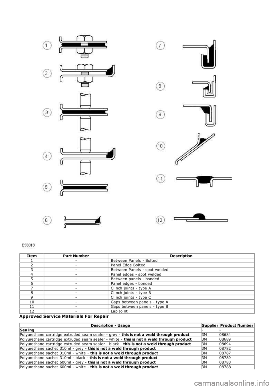
ItemPart NumberDescription
1-Between Panels - Bol ted2-Panel Edge Bolt ed
3-Between Panels - spot welded
4-Panel edges - s pot wel ded5-Between panels - bonded
6-Panel edges - bonded
7-Cli nch joint s - t ype A8-Cli nch joint s - t ype B
9-Cli nch joint s - t ype C
10-Gaps between panels - t ype A11-Gaps between panels - t ype B
12-Lap joi nt
Approved Service Materials For Repair
Description - UsageSupplierProduct Number
Sealing--Polyuret hane cartridge extruded seam seal er - grey - this is not a weld through product3M08684
Polyuret hane cartridge extruded seam seal er - whi te - this is not a w eld through product3M08689
Polyuret hane cartridge extruded seam seal er - bl ack - this is not a w eld through product3M08694Polyuret hane sachet 310ml - grey - this is not a w eld through product3M08782
Polyuret hane sachet 310ml - whi te - this is not a w eld through product3M08787
Polyuret hane sachet 310ml - bl ack - this is not a weld through product3M08789Polyuret hane sachet 600ml - grey - this is not a w eld through product3M08783
Polyuret hane sachet 600ml - whi te - this is not a w eld through product3M08788
Page 2521 of 3229
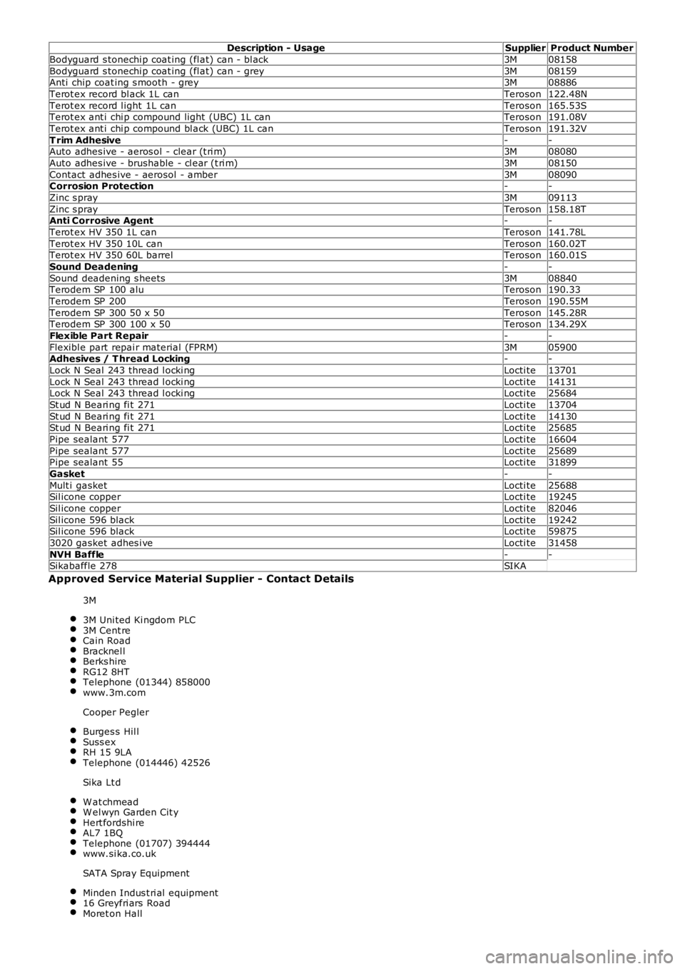
Description - UsageSupplierProduct Number
Bodyguard s tonechi p coat ing (fl at) can - bl ack3M08158
Bodyguard s tonechi p coat ing (fl at) can - grey3M08159Anti chip coat ing s mooth - grey3M08886
Terot ex record bl ack 1L canTeroson122.48N
Terot ex record l ight 1L canTeroson165.53STerot ex ant i chi p compound light (UBC) 1L canTeroson191.08V
Terot ex ant i chi p compound bl ack (UBC) 1L canTeroson191.32V
T rim Adhesive--Auto adhes ive - aeros ol - clear (t ri m)3M08080
Auto adhes ive - brushable - cl ear (t ri m)3M08150
Contact adhes ive - aerosol - amber3M08090Corrosion Protection--
Zinc s pray3M09113
Zinc s prayTeroson158.18TAnti Corrosive Agent--
Terot ex HV 350 1L canTeroson141.78L
Terot ex HV 350 10L canTeroson160.02TTerot ex HV 350 60L barrelTeroson160.01S
Sound Deadening--
Sound deadening s heets3M08840Terodem SP 100 aluTeroson190.33
Terodem SP 200Teroson190.55M
Terodem SP 300 50 x 50Teroson145.28RTerodem SP 300 100 x 50Teroson134.29X
Flexible Part Repair--
Flexibl e part repai r material (FPRM)3M05900Adhesives / T hread Locking--
Lock N Seal 243 thread l ocki ngLocti te13701
Lock N Seal 243 thread l ocki ngLocti te14131Lock N Seal 243 thread l ocki ngLocti te25684
St ud N Beari ng fi t 271Locti te13704
St ud N Beari ng fi t 271Locti te14130St ud N Beari ng fi t 271Locti te25685
Pipe sealant 577Locti te16604
Pipe sealant 577Locti te25689Pipe sealant 55Locti te31899
Gasket--
Mult i gasketLocti te25688Sil icone copperLocti te19245
Sil icone copperLocti te82046
Sil icone 596 blackLocti te19242Sil icone 596 blackLocti te59875
3020 gasket adhes i veLocti te31458
NVH Baffle--Sikabaffle 278SIKA
Approved Service Material Supplier - Contact Details
3M
3M Uni ted Ki ngdom PLC3M Cent reCain RoadBracknel lBerks hireRG12 8HTTelephone (01344) 858000www.3m.com
Cooper Pegler
Burges s Hil lSuss exRH 15 9LATelephone (014446) 42526
Sika Lt d
W at chmeadW el wyn Garden Cit yHert fordshi reAL7 1BQTelephone (01707) 394444www.si ka.co.uk
SATA Spray Equipment
Minden Indus t ri al equipment16 Greyfri ars RoadMoret on Hall